EHE004
ENERGY HARVESTING ELECTRONICS
FEATURES
DESCRIPTION
�
Simple and Easy Charge Management for
Vibration Energy Harvesting
�
Integrates directly with all Volture™
Energy Harvesters
The EHE004 is an energy harvesting power conditioning
circuit, which converts the AC output from a
piezoelectric energy harvester to a regulated DC output.
�
Parallel or Series Piezoelectric Connection
– Improved Efficiency
�
User Selectable DC Output
– (1.8V, 2.5V, 3.3V, 3.6V)
APPLICATIONS
�
Industrial Health Monitoring Network Sensors
�
Condition Based Maintenance Sensors
�
Wireless HVAC Sensors
�
Mobile Asset Tracking
�
Tire Pressure Sensors
�
Oil and Gas Sensors
�
All Air, Land, and Sea Vehicle Sensors
�
Battery and Hard Wired Power Replacement
TYPICAL APPLICATION
Figure 1: Representative energy harvesting system using a
Volture™ piezoelectric energy harvester and the EHE004
charge management electronics.
The EHE004 consists of a full-wave rectifier with
integrated charge management and DC-DC conversion,
and connects directly to any Volture™ piezoelectric
energy harvesting product. The DC output can be
configured to the following voltage settings: 1.8V, 2.5V,
3.3V, and 3.6V. The board includes 200 μF of storage
capacitance onboard - more capacitance can be added
if required.
The EHE004 utilizes the Linear Technology LTC3588-1
piezoelectric charge management IC - designed to
maximize total piezoelectric energy harvester output
and mechanical-to-electrical conversion efficiency with
medium to heavy loads.
Each Volture™ energy harvesting product has two
piezoelectric wafers. The EHE004 provides the user
with ability to connect these wafers either in series or
parallel. The series setting provides power output at
lower g levels for small vibration amplitude
applications. The parallel setting provides higher
average power output levels at higher vibration
amplitude levels.
For more information please contact Mide Tech. Corp
by emailing: volture@mide.com
CHARGE
MANAGEMENT
VIN
GND
VCC
OUT
VSTORE
MICRO
CONTROLLER
TX/RX
EHE004 CHARGE MANAGEMENT SYSTEM
SENSOR
REVISION N0. 002
REVISION DATE: 01-23-2013
SENSOR
SENSOR
1
�EHE004
ELECTRICAL CHARACTERISTICS
PRINCIPLE OF OPERATION
The LTC3588-1 Piezoelectric Energy Harvesting Power
Supply from Linear Technology is the primary
component on the EHE004. From Linear Technology’s
datasheet:
Referring to Figure 2b, The LTC3588-1 power supply IC
integrates an extremely low quiescent current voltage
comparator with a highly efficient buck regulator. The
buck regulator is activated when the rectified input
voltage, VCAP, rises above the pre-set undervoltage
lockout (UVLO) rising voltage threshold for the chosen
output voltage setting (Page 5 table ‘Specification’).
The regulator remains active until the input voltage has
been depleted to the UVLO falling threshold, at which
point the buck operation is disabled. Thus, for as long
as the load demand exceeds the input power (as in
typical sensor or battery charger applications), the
input voltage will hover between the UVLO rising and
falling thresholds. In cases where the input power
exceeds the load demand, the VCAP voltage will rise
beyond the UVLO rising threshold, storing the excess
power on the input capacitor. If the voltage at VCAP
exceeds approximately 20VDC, an internal voltage
clamp (5mA continuous rating) prevents damage to the
device.
“The LTC3588-1 integrates a low-loss full-wave
bridge rectifier with a high efficiency buck
converter to form a complete energy harvesting
solution optimized for high output impedance
energy sources such as piezoelectric transducers.
An ultralow quiescent current undervoltage lockout
(UVLO) mode with a wide hysteresis window
allows charge to accumulate on an input capacitor
until the buck converter can efficiently transfer a
portion of the stored charge to the output. In
regulation, the LTC3588-1 enters a sleep state in
which both input and output quiescent currents are
minimal. The buck converter turns on and off as
needed to maintain regulation.
Four output voltages, 1.8V, 2.5V, 3.3V and 3.6V, are
pin selectable with up to 100mA of continuous
output current; however, the output capacitor may
be sized to service a higher output current burst.
An input protective shunt set at 20V enables
greater energy storage for a given amount of input
capacitance.”
For more information on the LTC3588-1 please visit:
http://cds.linear.com/docs/Datasheet/35881fa.pdf
REVISION N0. 002
REVISION DATE: 01-23-2013
2
�EHE004
CONFIGURATION
The EHE004 has two means of signal rectification
(Normal and Superseries) and two ways to connect the
two piezoelectric wafers in a Volture™ product (Series
and Parallel). There are also four options for the
regulated DC output (1.8V, 2.5V, 3.3V, and 3.6V). In
total there are sixteen possible configuration settings.
The vibration environment and voltage requirements
dictated by the application will determine the best
configuration settings for the EHE004.
Maximum Power Point:
The efficiency of power transfer from the piezo to the
load, and thus normalized power (mW/G), will be at
maximum when the loaded piezo voltage (for moderate
to heavy loads, equal to the average UVLO voltage) is
approximately ½ its open-circuit voltage. However, the
ouput will continue to increase with increasing vibration
amplitude. For light loads where VCAP is not depleted
to the UVLO voltage during buck operation, transfer
efficiency is inconsequential as more power is
available than the load can use.
Normal vs. “Superseries”:
The difference between ‘Normal’ and ‘Superseries’, is the
bridge rectifier connection. In the normal mode of
operation, the bridge rectifier is operated in fullbridge
mode and its output voltage is half the peak-to-peak input
voltage minus two diode drops. In the “superseries”
configuration, the rectifier operates in a half-bridge mode
with only one diode drop. The normal mode is
recommended for maximum power output at moderate
input voltages, however the halfbridge mode will allow
operation from slightly lower minimum input voltages.
REVISION N0. 002
Parallel vs. Series operation:
All of MIDE’s Volture products contain two piezo
elements stacked in a bimorph configuration and
pinned out independently, allowing the user to choose
between parallel and series connection. On the EHE004
board, switch SW1 selects between parallel (doubled
current, lower input voltage) and series (doubled input
voltage, lower current) connection. Generally low level
vibrations are best suited to the series configuration
and high level vibrations are best suited to the parallel
configuration. However, the optimal setting will depend
on a number of factors including which Volture product
is being used and the parameters of the vibration
environment.
The table below shows the general configuration
settings for different application types. However, each
application is unique and the optimal settings will
depend on both the application and Volture™ or other
piezoelectric element used for the energy conversion.
Application
(Vibration Level)
Very Low Amplitude
General EHE004
Configuration Settings
SW1
SW3
Series
Superseries
Low to Moderate Amplitude Series
or Superseries
Moderate Amplitude
Parallel Normal
High Amplitude
Parallel Normal
Table 1: General configuration guide listing for various
applications. Every application is unique and may not
fit these general settings.
REVISION DATE: 01-23-2013
3
�EHE004
CONFIGURATION
How do I configure the EHE004?
Configuring the EHE004 is done by using the
combination of switches which appear on the top side
of the board. The switch at the top right, designated
SW3, controls the bridge rectifier connection. Place in
the “NORM” position (downward) for normal operation,
and the “SS” position for half-wave (“superseries”)
operation. The switch in the lower right hand side,
SW1, switches between parallel (downward, “Par.”
position) and series (upward, “Ser.” position) piezo
connection. The switch located in the top left hand
corner of the board, designated SW2, sets the output
voltage as marked below. In the legend below, the left
and right digit refer to the left and right toggle switch,
respectively, and the “1” or ON position is toward the
dot marked on the switch.
Switch #2 (SW2)
Switch #3 (SW3)
– DC Output Setting
– Rectification Method
SWITCH UP FIRST DECIMAL BECOMES = 00
SWITCH DOWN FIRST DECIMAL BECOMES = 10
SWITCH UP SECOND DECIMAL BECOMES = 00
SWITCH DOWN SECOND DECIMAL BECOMES = 01
SUPERSERIES – SWITCH UP
NORMAL – SWITCH DOWN
OUTPUT VOLTAGE
Switch #1 (SW1)
SWITCH #2 LEFT & RIGHT
00 = 1.8V = UP UP
10 = 3.3V = DOWN UP
01 = 2.5V = UP DOWN
11 = 3.6V = DOWN DOWN
– Piezo Connection
SERIES – SWITCH UP
PARALLEL – SWITCH DOWN
CONNECTION INFORMATION
The terminal block at the bottom-left of the board
(solder or screw terminals) provides the regulated
output and other signals from the EHE004. The
connections from left to right are:
GND – Electrical ground
VOUT – Regulated output voltage
VCAP – Test point for measuring the voltage across the
input capacitor(s). Additional capacitance can be
added between this terminal & GND as needed.
PGOOD – Active-high Power Good signal. This signal will
be high (true) when the output is in regulation
and will go low (false) when the output voltage
drops below 92% of its regulated value. This will
typically occur once the input voltage falls below
the UVLO threshold or if the maximum output
current is exceeded.
REVISION N0. 002
In addition, a low-voltage auxiliary power source, such
as a solar cell, can be added by soldering to the AUX+
and AUX- pads at the bottom-left corner of the board,
provided the source complies with the absolute
maximum ratings set forth above (VAC≤18V,
RSOURCE>400OHMS, SW3=SUPERSERIES). A blocking
diode (400mV typical voltage drop) in series with the
AUX input prevents reverse leakage across the device.
REVISION DATE: 01-23-2013
4
�EHE004
SPECIFICATIONS
The following provides a brief summary of the most
important specifications of the EHE004. For complete
specifications and performance plots for the
LTC3588-1 charge management IC, please refer to the
LTC3588-1 data sheet.
For Volture™ specifications, such as typical
relationships between frequency, tip mass and output
voltage for each product, please refer to the Volture™
data sheet.
Specification
Value (typical @ 25°C)
Input capacitance
200uF (stock product – custom values available
upon request)
Output capacitance
10uF
Maximum Input Voltage
18V (low impedance sources) 1
Maximum Peak Protective Shunt Current
25mA (1ms duration)
Maximum Continuous Protective Shunt Current
5mA
Quiescent Current
UVLO
450nA
Buck Enabled, Sleeping
(Vin = 4.5V)
950nA
Buck Enabled, Sleeping
(Vin = 18V)
1.7uA
Buck Enabled, Active 2
150uA
Maximum Output Current
100mA
NOTE 1: An internal clamp circuit limits the input
voltage to 20V; the maximum input voltage stated may
be safely exceeded provided the maximum input
current condition is satisfied.
REVISION N0. 002
NOTE 2: Does not include active switching or inductor
currents (Isw=0). Dynamic supply current is higher
due to gate charge being delivered at the switching
frequency.
REVISION DATE: 01-23-2013
5
�EHE004
OPERATION
Vout
setting (V)
UVLO
rising (V)
UVLO
falling (V)
Vmpp (V)
1.8
4.04
2.87
7.4
3.1
Vripple @
Vin=UVLO
(mV) 3
120
2.5
4.04
2.87
7.5
3.1
120
160
3.3
5.05
3.67
9.3
3.6
140
280
3.6
5.05
4.02
9.6
3.6
160
300
NOTE 1: Approximate maximum power point (opencircuit piezo voltage) at which power transfer to the
load is maximized.
1
Vmin (V)
2
Vripple @
Vin=20 (mV)3
160
NOTE 3: Ripple values measured at no load and the
10uF onboard output capacitance.
NOTE 2: Minimum start-up voltage in halfbridge
(“superseries”) configuration.
PERFORMANCE PLOTS
Volture™ energy harvesting products can be found on
the Volture™ datasheet.
V25W, 1.8V, 75 Hz, 2.4 gram Tip Mass, Reg Cap
2
Normal, Series
Normal, Parallel
Superseries, Series
Superseries, Parallel
1.8
1.6
Average Power (mW)
The EHE004 performance was measured while
connected to a Volture™ V25W piezoelectric energy
harvester. The system was properly clamped and
tuned using the procedures detailed in the Volture™
datasheet. The assembly was attached to a shake
table to generate vibrations to test the system. The
shake table was driven by a function generator and the
amplitude was measured with an accelerometer. To
determine average power, the output duty cycle at the
known output voltage over a fixed 1.00K-ohm load was
measured.
1.4
1.2
1
0.8
0.6
0.4
Performance measurements were taken at 0.25g,
0.50g, 0.75g, and 1g amplitudes. The lowest amplitude
at which the EHE004 input exceeded the UVLO
threshold, producing a usable output, was also
recorded. The figure below shows the results for these
tests. For the same amplitude conditions, other
Volture™ products would exhibit similar performance
characteristics though with different power output
levels. Typical average power output levels for
REVISION N0. 002
0.2
0
0
0.2
0.4
0.6
0.8
1
Amplitude (g)
This representative figure shows how the different
settings on the EHE004 can be used most efficiently
given the vibration profile that this specific energy
harvester with this tip mass was subjected to. For lowest
amplitude vibrations (in this instance below 0.175 gee)
REVISION DATE: 01-23-2013
6
�EHE004
PERFORMANCE PLOTS
the only setting that was able to provide any output was
the Superseries, Parallel setting. From approximately
0.175 gee to 0.25 gee the Normal, Series setting was
best. For all amplitudes above 0.25 gee the Normal,
Parallel was the most efficient. It should be noted that
these curves will vary substantially depending on the
product that is used as well as the tip mass that is used
to tune the product. In conclusion what this
representative curve shows is that the piezo’s output
energy and voltage for certain settings will allow the
system to operate closer to the half open circuit voltage
causing more efficient operation. For low level vibration
the series setting is needed to get the piezo voltage output
to reach the minimum voltage to operate the EHE004.
BOARD SCHEMATIC AND DIMENSIONS
Volture™
Product
0.100
0.700
EHE004
A
2 X 0.089
2-56 THRU
1.031
V22B / V22BL N/A
N/A
N/A
V20W / V25W 1.250
0.588
0.986
V21B / V21BL 0.600
0.633
1.031
V22B / V22BL N/A
N/A
N/A
VOS1
VOS0
3588-1
0
0
1
1
0
1
0
1
1.8V
2.5V
3.3V
3.6V
U1
SW1
P$6
2
C2 + C100 C101
100nF
AUX -
VCAP
J4
100uF
3
C1
1uF
1
100uF
2
3
P$1
SW3
1
P$4
P$3
1
2
3
4
5
GND
PZ1 PGOOD
PZ2
D0
CAP
D1
VIN
VIN2
SW VOUT
3.45V
4.1V
4.5V
5.0V
GND
PAD
9 VOS0
8 VOS1
7
6 VIN2
LTC3588MSE
L1
10uH
3588-2
PGOOD
VCAP P$3
GND
SW1: Piezo Conection
Down: Wafers in parallel
Up: Wafers in series
47uF
C4
DNP
GND
REVISION N0. 002
V+
P$2
P$1
C3
GND
SW3/J4 “Superseries” select
1-2: Normal bridges operation
2-3: Halfbridge operation
PGOOD P$4
4.7uF
V+
AUX +
D9
QPXX_RA
0.633
SW2: Output Voltage Select
1
BAT43W
P$2
V21B / V21BL 0.600
Figure 2: EHE004 Board dimensions when used with one of
Mide’s Volture energy harvesters. Maximum component
height on the board is 0.10”. All dimensions are in inches.
VIN2
VNS0 2
3
SW2
CAS-D20
4
VNS1 5
6
GND
P$5
0.986
SW2
Volture V2xx pin 1-4 is as follows:
Piezo wafers on pin 1&2, 3&4
J3
0.588
+VOUT
B
V20W / V25W 1.250
GND
J1
GND
VOLTURE
1.600
B with J3
Connector
V+
PRODUCT
1.450
B without J3
Connector
C5
VOLTURE PRODUCT
A
Figure 2b: EHE004 Schematic
REVISION DATE: 01-23-2013
7
�EHE004
BOARD SCHEMATIC AND DIMENSIONS
Table 1: EHE004 Bill of Materials
Qty
Parts (Ref Des.) Package
Value
Manufacturer Part Number
1
C1
0603
1uF
Yageo, CC0603ZRY5V7BB105
1
C5
0603
4.7uF
Murata, GRM188R60J475ME19D
1
L1
1210
10uH
Taiyo Yuden, CBC3225T100MR
1
C3
1206
47uF
Kemet, C1206C476M9PACTU
1
C2
0603
100nF
TDK, C1608Y5V1E104Z
2
C100, C101
Case D (7343 Metric)
100uF
Kemet, T491X107K025ZT
1
J1
0.100" Screw Terminals
1
D9
SOD80C
1
SW3
CAS-120
Copal Electronics, CAS-120TA
1
SW2
CAS-D20
Copal Electronics, CAS-D20TB
1
U1
10-MSOP
Linear Technology, LTC3588EMSE-1#PBF
1
J3
0.100" x 4
Sullins, PPTC041LGBN-R
1
SW1
EG1390
E-Switch, EG1390A
Phoenix Contact, 1725672
BAT43W
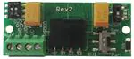
Figure 3: PCB top side
Micro Commercial Co., BAT43W-TP
Figure 4: PCB bottom side
REVISION N0. 002
REVISION DATE: 01-23-2013
8
�