Adafruit 4-Channel ADC Breakouts
Created by Liz Clark
https://learn.adafruit.com/adafruit-4-channel-adc-breakouts
Last updated on 2022-07-21 10:38:47 AM EDT
©Adafruit Industries
Page 1 of 33
�Table of Contents
Overview
5
• ADS1115 Features:
• ADS1015 Features:
Pinouts
•
•
•
•
•
•
Power Pins
I2C Logic Pins
Address Jumper
Address Pin
Other Pins
Power LED and Jumper
Assembly and Wiring
•
•
•
•
•
•
•
•
•
•
15
Single Ended vs. Differential Inputs:
Which should I use?
Single Ended Connections:
Differential Connections:
Python & CircuitPython
•
•
•
•
•
•
•
•
•
•
•
•
12
Assembly:
Prepare the header strip
Position the breakout board
Solder!
Wiring:
Power
I2C Connections
I2C "Classic"
I2C Addressing
Multiple Boards
Signal Connections
•
•
•
•
9
17
CircuitPython Microcontroller Wiring
Python Computer Wiring
CircuitPython Installation of ADS1x15Library
Python Installation of ADS1x15 Library
CircuitPython & Python Usage
Single Ended Mode
Differential Mode
Gain
Single Mode
Continuous Mode
Challenges to Reading Quickly
More Info
Python Docs
24
Arduino Code
25
•
•
•
•
•
Wiring
Construction and Initialization:
Single Ended Conversion:
Differential Conversion:
Comparator Operation:
©Adafruit Industries
Page 2 of 33
�• Adjusting Gain
• Example
Arduino Docs
30
Downloads
30
•
•
•
•
Software
Files
Schematic and Fab Print STEMMA QT Version (Identical For Both)
Schematic and Fab Print Original Version (Identical For Both)
©Adafruit Industries
Page 3 of 33
�©Adafruit Industries
Page 4 of 33
�Overview
The ADS1115 and ADS1015 4-channel breakout boards are perfect for adding highresolution analog to digital conversion to any microprocessor-based project. These
boards can run with power and logic signals between 2v to 5v, so they are compatible
with all common 3.3v and 5v processors. As many of 4 of these boards can be
controlled from the same 2-wire I2C bus, giving you up to 16 single-ended or 8
differential channels. A programmable gain amplifier provides up to x16 gain for small
signals.
©Adafruit Industries
Page 5 of 33
�These two boards are very similar, differing only in resolution and speed. The ADS1115
provides 16-bit precision at 860 samples/second, while the ADS1015 provides 12-bit
precision at 3300 samples/second.
To get you going fast, we spun up a custom-made PCB in the STEMMA QT form
factor (https://adafru.it/LBQ), making it easy to interface with. The STEMMA QT
connectors (https://adafru.it/JqB) on either side are compatible with the SparkFun
Qwiic (https://adafru.it/Fpw) I2C connectors. This allows you to make solderless
connections between your development board and either the ADS1115 or ADS1015.
You can chain the boards with a wide range of other sensors and accessories using a
compatible cable (https://adafru.it/JnB).
©Adafruit Industries
Page 6 of 33
�ADS1115 Features:
• WIDE SUPPLY RANGE: 2.0V to 5.5V
• LOW CURRENT CONSUMPTION: Continuous Mode: Only 150µA Single-Shot
Mode: Auto Shut-Down
• PROGRAMMABLE DATA RATE: 8SPS to 860SPS
• INTERNAL LOW-DRIFT VOLTAGE REFERENCE
• INTERNAL OSCILLATOR
• INTERNAL PGA
• I2C INTERFACE: Pin-Selectable Addresses
• FOUR SINGLE-ENDED OR TWO DIFFERENTIAL INPUTS
• PROGRAMMABLE COMPARATOR
• This board/chip uses I2C 7-bit addresses between 0x48-0x4B, selectable with
jumpers
ADS1015 Features:
• WIDE SUPPLY RANGE: 2.0V to 5.5V
• LOW CURRENT CONSUMPTION: Continuous Mode: Only 150µA Single-Shot
Mode: Auto Shut-Down
• PROGRAMMABLE DATA RATE: 128SPS to 3.3kSPS
• INTERNAL LOW-DRIFT VOLTAGE REFERENCE
• INTERNAL OSCILLATOR
• INTERNAL PGA
• I2C INTERFACE: Pin-Selectable Addresses
• FOUR SINGLE-ENDED OR TWO DIFFERENTIAL INPUTS
©Adafruit Industries
Page 7 of 33
�• PROGRAMMABLE COMPARATOR
• This board/chip uses I2C 7-bit addresses between 0x48-0x4B, selectable with
jumpers
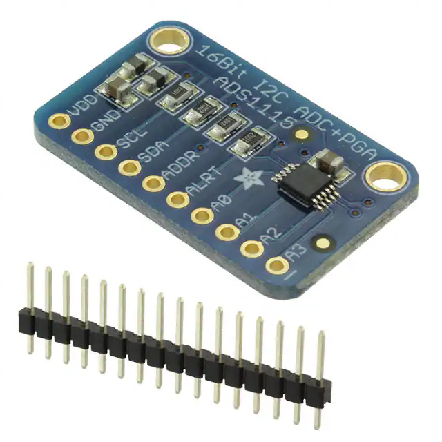
There are two versions of this board - the STEMMA QT version shown above, and
the original header-only version shown below. Code works the same on both!
©Adafruit Industries
Page 8 of 33
�Pinouts
The default I2C address is 0x48.
Power Pins
The ADC on the breakout requires between 2V to 5V power/logic, and can be easily
used with most microcontrollers from an Arduino to a Feather or something else.
• VIN - this is the power pin. Acceptable voltages are 2V to 5V. To power the
board, give it the same power as the logic level of your microcontroller - e.g. for
a 5V micro like Arduino, use 5V.
• GND - common ground for power and logic
I2C Logic Pins
• SCL - I2C clock pin, connect to your microcontroller's I2C clock line. This pin
has a 10K pullup to VIN
• SDA -I2C data pin, connect to your microcontroller's I2C data line. This pin has
a 10K pullup to VIN.
©Adafruit Industries
Page 9 of 33
�• STEMMA QT (https://adafru.it/Ft4) - These connectors allow you to connect to
development boards with STEMMA QT connectors, or to other things, with vario
us associated accessories (https://adafru.it/Ft6).
Address Jumper
On the back of the board is one address jumper, labeled A0, below the I2C Addr label
on the board silk. This jumper allows you to chain up to 2 of these boards on the
same pair of I2C clock and data pins. To do so, you solder the jumper "closed" by
connecting the two pads.
The default I2C address is 0x48. The other address options can be calculated by
“adding” the A0 to the base of 0x48.
A0 sets the lowest bit with a value of 1. The final address is 0x48 + A0 which would
be 0x49.
If A0 is soldered closed, the address is 0x48 + 1 = 0x49
The table below shows all possible addresses, and whether the pin(s) should be high
(closed) or low (open).
Address Pin
• ADDR - I2C address selection pin.
The ADS11x5 chips have a base 7-bit I2C address of 0x48 (1001000) and a clever
addressing scheme that allows four different addresses using just one address pin
©Adafruit Industries
Page 10 of 33
�(named ADDR for ADdRess). To program the address, connect the address pin as
follows:
Other Pins
• ALRT - Digital comparator output or conversion ready, can be set up and used
for interrupt / asynchronous read.
• A+ and A- - ADC power supply (VIN through a ferrite) and ADC ground (digital
GND through a ferrite) these are OUTPUTs not inputs!
• A0, A1, A2, A3 - ADC input pins for each channel.
Power LED and Jumper
• Power LED - In the upper left corner, above the STEMMA connector, on the front
of the board, is the power LED, labeled on. It is the green LED.
• LED jumper - In the upper right corner on the back of the board is a jumper for
the power LED. If you wish to disable the power LED, simply cut the trace on this
jumper.
©Adafruit Industries
Page 11 of 33
�Assembly and Wiring
Assembly:
The board comes with all surface-mount parts pre-soldered. For breadboard use, the
included header-strip should be soldered on:
Prepare the header strip
Cut the supplied header strip to length
and insert it long-pins-down in your
breadboard to hold it for soldering.
Position the breakout board
Place the breakout board on the header
pins.
Solder!
Solder each pin for a good electrical
connection.
©Adafruit Industries
Page 12 of 33
�Wiring:
Power
First connect VDD and GND. These boards will work with either a 3.3v or a 5v supply.
The diagram below shows connection to the Arduino 5v pin.
The absolute maximum analog input voltage is VDD + 0.3v. To avoid damage to
the chip, do not attempt to measure voltages greater than VDD.
I2C Connections
I2C requires just 2 pins to communicate. These can be shared with other I2C
devices. For R3 and later Arduinos (including MEGA and DUE models), connect SDA>SDA and SCL->SCL.
I2C "Classic"
For older Arduino boards without dedicated SDA and SCL pins, connect as shown
below. (For older Arduino Megas, SDA and SCL are on pins 20 and 21)
©Adafruit Industries
Page 13 of 33
�I2C Addressing
The ADS11x5 chips have a base 7-bit I2C address of 0x48 (1001000) and a clever
addressing scheme that allows four different addresses using just one address pin
(named ADR for ADdRess). To program the address, connect the address pin as
follows:
The following diagram shows one board addressed as 0x48:
©Adafruit Industries
Page 14 of 33
�Multiple Boards
By assigning each board a different address, up to 4 boards can be connected as
below:
Signal Connections
©Adafruit Industries
Page 15 of 33
�Single Ended vs. Differential Inputs:
The ADS1x15 breakouts support up to 4 SIngle Ended or 2 Differential inputs.
Single Ended inputs measure the voltage between the analog input channel (A0-A3)
and analog ground (GND).
Differential inputs measure the voltage between two analog input channels. (A0&A1
or A2&A3).
Which should I use?
Single ended inputs give you twice as many inputs. So why would you want to use
differential inputs?
Single ended inputs can, by definition, only measure positive voltages. Without the
sign bit, you only get an effective 15 bit resolution.
In addition to providing the full 16 bits of resolution and the ability to measure
negative voltages, Differential measurements offer more immunity from
electromagnetic noise. This is useful when using long signal wires or operating in an
electrically noisy environment. This is also desirable when dealing with small signals
requiring high gain, since the gain will amplify the noise as well as the signal.
Single Ended Connections:
Connect the signal wire to one of the analog input channels (A0 - A3). Connect the
ground wire to GND. This diagram shows how to connect an ADXL335 to for
measurement of the X, Y and Z axis on analog channels A0, A1 and A2.
©Adafruit Industries
Page 16 of 33
�Differential Connections:
Differential measurements use a pair of input pins, either A0&A1 or A2&A3. The
following diagram shows connections for differential measurement of the battery
voltage on a LiPo charger board.
All input signals to these devices must be between ground potential and VCC. If
your source signal produces negative voltages, they must be offset to fall within
the GND to VCC range of the ASD1x15.
Python & CircuitPython
It's easy to use the ADS1115 and ADS1015 ADC with CircuitPython and the Adafruit
CircuitPython ADS1x15 (https://adafru.it/C1n) module. This module allows you to easily
write Python code that reads the analog input values.
You can use this ADC with any CircuitPython microcontroller board or with a computer
that has GPIO and Python thanks to Adafruit_Blinka, our CircuitPython-for-Python
compatibility library (https://adafru.it/BSN).
CircuitPython Microcontroller Wiring
First wire up the ADC to your board exactly as shown on the previous pages for
Arduino using an I2C interface. Here's an example of wiring a Feather M0 to the
ADS1x15 with I2C:
©Adafruit Industries
Page 17 of 33
�Board 3V
(red wire in STEMMA QT version) to
ADS1x15 VDD - Remember the maximum
input voltage to any ADC channel cannot
exceed this VDD 3V value!
Board GND (black wire in STEMMA QT
version) to ADS1x15 GND
Board SCL (yellow wire in STEMMA QT
version) to ADS1x15 SCL
Board SDA (blue wire in STEMMA QT
version) to ADS1x15 SDA
Python Computer Wiring
Since there's dozens of Linux computers/boards you can use we will show wiring for
Raspberry Pi. For other platforms, please visit the guide for CircuitPython on Linux to
see whether your platform is supported (https://adafru.it/BSN).
Here's the Raspberry Pi wired to the ADS1015 with I2C:
©Adafruit Industries
Page 18 of 33
�Pi 3V (red wire in STEMMA QT version)
to ADS1x15 VDD - Remember the maximum
input voltage to any ADC channel cannot
exceed this VDD 3V value!
Pi GND (black wire in STEMMA QT version)
to ADS1x15 GND
Pi SCL (yellow wire in STEMMA QT
version) to ADS1x15 SCL
Pi SDA (blue wire in STEMMA QT version)
to ADS1x15 SDA
CircuitPython Installation of ADS1x15Library
Next you'll need to install the Adafruit CircuitPython ADS1x15 (https://adafru.it/C1n) libr
ary on your CircuitPython board.
First make sure you are running the latest version of Adafruit CircuitPython (https://
adafru.it/tBa) for your board.
©Adafruit Industries
Page 19 of 33
�Next you'll need to install the necessary libraries to use the hardware--carefully follow
the steps to find and install these libraries from Adafruit's CircuitPython library bundle
(https://adafru.it/zdx). For example the Circuit Playground Express guide has a great
page on how to install the library bundle (https://adafru.it/C9M) for both express and
non-express boards.
Remember for non-express boards like the Trinket M0, Gemma M0, and Feather/
Metro M0 basic you'll need to manually install the necessary libraries from the bundle:
• adafruit_ads1x15
• adafruit_bus_device
You can also download the adafruit_ads1x15 folder from its releases page on Github (
https://adafru.it/C1o).
Before continuing make sure your board's lib folder or root filesystem has the adafruit
_ads1x15 and adafruit_bus_device files and folders copied over.
Next connect to the board's serial REPL (https://adafru.it/pMf)so you are at the
CircuitPython >>> prompt.
Python Installation of ADS1x15 Library
You'll need to install the Adafruit_Blinka (https://adafru.it/BJX) library that provides the
CircuitPython support in Python. This may also require enabling I2C on your platform
and verifying you are running Python 3. Since each platform is a little different, and
Linux changes often, please visit the CircuitPython on Linux guide to get your
computer ready (https://adafru.it/BSN)!
Once that's done, from your command line run the following command:
• sudo pip3 install adafruit-circuitpython-ads1x15
If your default Python is version 3 you may need to run 'pip' instead. Just make sure
you aren't trying to use CircuitPython on Python 2.x, it isn't supported!
©Adafruit Industries
Page 20 of 33
�CircuitPython & Python Usage
To demonstrate the usage of the ADC we will initialize it and read the ADC channel
values interactively using the REPL. First run the following code to import the
necessary modules and initialize the I2C bus:
import board
import busio
i2c = busio.I2C(board.SCL, board.SDA)
Next, import the module for the board you are using. For the ADS1015, use:
import adafruit_ads1x15.ads1015 as ADS
OR, for the ADS1115, use:
import adafruit_ads1x15.ads1115 as ADS
Note that we are renaming each import to ADS for convenience.
The final import needed is for the ADS1x15 library's version of AnalogIn:
from adafruit_ads1x15.analog_in import AnalogIn
which provides behavior similar to the core AnalogIn library (https://adafru.it/Bep), but
is specific to the ADS1x15 ADC's.
OK, now we can actually create the ADC object. For the ADS1015, use:
ads = ADS.ADS1015(i2c)
OR, for the ADS1115, use:
ads = ADS.ADS1115(i2c)
Now let's see how to get values from the board. You can use these boards in either
single ended or differential mode. The usage for the two modes are slightly different,
so we'll go over them separately.
©Adafruit Industries
Page 21 of 33
�Single Ended Mode
For single ended mode we use AnalogIn to create the analog input channel, providing
the ADC object and the pin to which the signal is attached. Here, we use pin 0:
chan = AnalogIn(ads, ADS.P0)
To set up additional channels, use the same syntax but provide a different pin.
Now you can read the raw value and voltage of the channel using either the the value
or voltage property.
print(chan.value, chan.voltage)
Differential Mode
For differential mode, you provide two pins when setting up the ADC channel. The
reading will be the difference between the two. Here, we use pin 0 and 1:
chan = AnalogIn(ads, ADS.P0, ADS.P1)
You can create more channels by doing this again with different pins. However, note
that not all pin combinations are possible. See the datasheets for details.
Once the channel is created, getting the readings is the same as before:
print(chan.value, chan.voltage)
©Adafruit Industries
Page 22 of 33
�Gain
Both the ADS1015 and the ADS1115 have a Programmable Gain (PGA) that you can set
to amplify the incoming signal before it reaches the ADC. The available settings and
associated Full Scale (FS) voltage range are shown in Table 3 of the datasheet.
You set the gain to one of the values using the gain property, like this:
ads.gain = 16
Note that setting gain will affect the raw ADC value but not the voltage (expect
for variance due to noise). For example:
>>> ads.gain
1
>>> chan.value, chan.voltage
(84, 0.168082)
>>> ads.gain = 16
>>> ads.gain
16
>>> chan.value, chan.voltage
(1335, 0.167081)
>>>
The value changed from 84 to 1335, which is pretty close to 84 x 16 = 1344.
However, the voltage returned in both cases is still the actual input voltage of
~0.168 V.
©Adafruit Industries
Page 23 of 33
�Single Mode
Single mode (not to be confused with single-ended mode) always waits until the
analog to digital conversion is completed by the ADC to read the value. This is slower,
but it is really the only way to read from more than one pin on the ADC. This is the
default mode, but if you ever need to manually set it, here's how:
ads.mode = Mode.SINGLE
Continuous Mode
In continuous mode, the board will read the latest value that the ADS1x15 device has
converted. This is faster as it does not have to wait for the ADC to finish converting
the value, but it only really works when reading data from one of the four pins on the
ADC. You can set it to continuous mode using the line below:
ads.mode = Mode.CONTINUOUS
Challenges to Reading Quickly
The best approach to reading data from the ADC quickly would be to use interrupts
which would enable the digital value to be recorded from the desired pin as soon as
the ADC has converted it. However, CircuitPython does not support the use of
interrupts, so this isn't possible. To partially solve this, the continuous mode was
added, which will always return the most recently converted value with very low
latency since it does not wait for the new value to be ready.
More Info
The above examples cover the basic setup and usage using default settings. For
more details, see the documentation (https://adafru.it/C1p).
Python Docs
Python Docs (https://adafru.it/C1p)
©Adafruit Industries
Page 24 of 33
�Arduino Code
Wiring
Hooking up the ADS1x15 to your Arduino is easy:
For Arduino Metro and other 5V microcontrollers, use 5V for Vin. For Feather and
other 3V microcontrollers, use 3.3V
©Adafruit Industries
Page 25 of 33
�Connect SCL on the Metro to SCL (yellow
wire in STEMMA QT version) on the
ADS1x15
Connect SDA on the Metro to SDA (blue
wire in STEMMA QT version) on the
ADS1x15
Connect GND on the Metro to GND (black
wire in STEMMA QT version) on the
ADS1x15
Connect 5V on the Arduino/Metro
to VIN (red wire in STEMMA QT version) on
the ADS1x15
The Adafruit_ADS1X15 library supports both single-ended and differential readings as
well as comparator operations on both the ADS1015 and ADS1115 breakout boards.
The library uses the wiring library for I2C communication, so wiring.h must be
included.
Construction and Initialization:
Adafruit_ADS1015();
Construct an instance of an ADS1015
©Adafruit Industries
Page 26 of 33
�Adafruit_ADS1115();
Construct an instance of an ADS1115
begin();
Initialize the ADC for operation using the default address and I2C bus.
begin(0x49);
Initialize the ADC for operation using specified address of 0x49.
Example:
The following examples assume an ADS1015 and use a 3 mV/bit scaling factor.
For the higher-resolution ADS1115, the scaling factor would be 188uV/bit.
#include <Wire.h>
#include <Adafruit_ADS1X15.h>
Adafruit_ADS1015 ads1015;
Adafruit_ADS1115 ads1115;
// Construct an ads1015
// Construct an ads1115
void setup(void)
{
ads1015.begin(); // Initialize ads1015 at the default address 0x48
ads1115.begin(0x49); // Initialize ads1115 at address 0x49
}
Single Ended Conversion:
uint16_t readADC_SingleEnded(uint8_t channel);
Perform a single-ended analog to digital conversion on the specified channel.
Example:
#include <Wire.h>
#include <Adafruit_ADS1X15.h>
Adafruit_ADS1015 ads1015;
void setup(void)
{
Serial.begin(9600);
Serial.println("Hello!");
Serial.println("Getting single-ended readings from AIN0..3");
Serial.println("ADC Range: +/- 6.144V (1 bit = 3mV)");
ads1015.begin();
©Adafruit Industries
Page 27 of 33
�}
void loop(void)
{
int16_t adc0, adc1, adc2, adc3;
adc0 = ads1015.readADC_SingleEnded(0);
adc1 = ads1015.readADC_SingleEnded(1);
adc2 = ads1015.readADC_SingleEnded(2);
adc3 = ads1015.readADC_SingleEnded(3);
Serial.print("AIN0: "); Serial.println(adc0);
Serial.print("AIN1: "); Serial.println(adc1);
Serial.print("AIN2: "); Serial.println(adc2);
Serial.print("AIN3: "); Serial.println(adc3);
Serial.println(" ");
delay(1000);
}
Differential Conversion:
int16_t readADC_Differential_0_1(void);
Perform a differential analog to digital conversion on the voltage between channels 0
and 1.
int16_t readADC_Differential_2_3(void);
Perform a differential analog to digital conversion on the voltage between channels 2
and 3.
Example:
#include <Wire.h>
#include <Adafruit_ADS1X15.h>
Adafruit_ADS1015 ads1015;
void setup(void)
{
Serial.begin(9600);
Serial.println("Hello!");
Serial.println("Getting differential reading from AIN0 (P) and AIN1 (N)");
Serial.println("ADC Range: +/- 6.144V (1 bit = 3mV)");
ads1015.begin();
}
void loop(void)
{
int16_t results;
results = ads1015.readADC_Differential_0_1();
Serial.print("Differential: "); Serial.print(results); Serial.print("(");
Serial.print(results * 3); Serial.println("mV)");
delay(1000);
}
©Adafruit Industries
Page 28 of 33
�Comparator Operation:
Comparator mode allows you to compare an input voltage with a threshold level and
generate an alert signal (on the ALRT pin) if the threshold is exceeded. This pin can
be polled with a digital input pin, or it can be configured to generate an interrupt.
void startComparator_SingleEnded(uint8_t channel, int16_t threshold);
Set the threshold and channel for comparator operation.
int16_t getLastConversionResults();
Get the last conversion result and clear the comparator.
Example:
#include <Wire.h>
#include <Adafruit_ADS1X15.h>
Adafruit_ADS1015 ads1015;
void setup(void)
{
Serial.begin(9600);
Serial.println("Hello!");
Serial.println("Single-ended readings from AIN0 with >3.0V comparator");
Serial.println("ADC Range: +/- 6.144V (1 bit = 3mV)");
Serial.println("Comparator Threshold: 1000 (3.000V)");
ads1015.begin();
// Setup 3V comparator on channel 0
ads1015.startComparator_SingleEnded(0, 1000);
}
void loop(void)
{
int16_t adc0;
// Comparator will only de-assert after a read
adc0 = ads1015.getLastConversionResults();
Serial.print("AIN0: "); Serial.println(adc0);
delay(100);
}
Adjusting Gain
To boost small signals, the gain can be adjusted on the ADS1x15 chips in the following
steps:
• GAIN_TWOTHIRDS (for an input range of +/- 6.144V)
• GAIN_ONE (for an input range of +/-4.096V)
• GAIN_TWO (for an input range of +/-2.048V)
• GAIN_FOUR (for an input range of +/-1.024V)
• GAIN_EIGHT (for an input range of +/-0.512V)
©Adafruit Industries
Page 29 of 33
�• GAIN_SIXTEEN (for an input range of +/-0.256V)
adsGain_t getGain(void)
Reads the current gain value (default = 2/3x)
adsGain_t gain = getGain();
void setGain(adsGain_t gain)
Sets the gain for the ADS1x15
ads1015.setGain(GAIN_TWOTHIRDS);
// 2/3x gain +/- 6.144V
1 bit = 3mV (default)
//
//
//
//
//
//
//
//
//
//
1
1
1
1
1
ads1015.setGain(GAIN_ONE);
ads1015.setGain(GAIN_TWO);
ads1015.setGain(GAIN_FOUR);
ads1015.setGain(GAIN_EIGHT);
ads1015.setGain(GAIN_SIXTEEN);
1x gain
2x gain
4x gain
8x gain
16x gain
+/+/+/+/+/-
4.096V
2.048V
1.024V
0.512V
0.256V
bit
bit
bit
bit
bit
=
=
=
=
=
2mV
1mV
0.5mV
0.25mV
0.125mV
Example
If we had an analog sensor with an output voltage ~1V (a TMP36, for example), we
could set the gain on the ADC to GAIN_FOUR, which would give us a +/-1.024V range.
This would push the 1V input signal over the entire 12-bit or 16-bit range of the ADC,
compared to the very limited range 1V would cover without adjusting the gain settings
// Set the gain to 4x, for an input range of +/- 1.024V
// 1-bit = 0.5V on the ADS1015 with this gain setting
ads1015.setGain(GAIN_FOUR);
Arduino Docs
Arduino Docs (https://adafru.it/-Qb)
Downloads
Software
• ADS1x15 Library for Arduino (https://adafru.it/aSt)
©Adafruit Industries
Page 30 of 33
�Files
• EagleCAD PCB Files on GitHub (https://adafru.it/aSu)
• ADS1015 Fritzing object (original version) in the Adafruit Fritzing Library (https://
adafru.it/-QA)
• ADS1115 Fritzing object (original version) in the Adafruit Fritzing Library (https://
adafru.it/-QB)
• ADS1015 Fritzing object (STEMMA QT version) in the Adafruit Fritzing Library (htt
ps://adafru.it/-QC)
• ADS1115 Fritzing object (STEMMA QT version) in the Adafruit Fritzing Library (htt
ps://adafru.it/-QD)
• ADS1015 Datasheet (https://adafru.it/aSv)
• ADS1115 Datasheet (https://adafru.it/aSw)
Schematic and Fab Print STEMMA QT Version (Identical
For Both)
©Adafruit Industries
Page 31 of 33
�Schematic and Fab Print Original Version (Identical For
Both)
©Adafruit Industries
Page 32 of 33
�©Adafruit Industries
Page 33 of 33
�


 工商网监
湘ICP备2023018690号
工商网监
湘ICP备2023018690号

