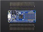
Adafruit Feather 32u4 Basic Proto
Created by lady ada
https://learn.adafruit.com/adafruit-feather-32u4-basic-proto
Last updated on 2022-07-27 04:15:25 PM EDT
©Adafruit Industries
Page 1 of 36
�Table of Contents
Overview
3
Pinouts
6
• Power Pins
• Logic pins
• Other Pins!
Assembly
•
•
•
•
•
•
•
•
•
Header Options!
Soldering in Plain Headers
Prepare the header strip:
Add the breakout board:
And Solder!
Soldering on Female Header
Tape In Place
Flip & Tack Solder
And Solder!
Power Management
•
•
•
•
•
8
18
Battery + USB Power
Power Supplies
Measuring Battery
ENable pin
Alternative Power Options
Arduino IDE Setup
22
Using with Arduino IDE
25
•
•
•
•
Install Drivers (Windows 7 Only)
Blink
Manually bootloading
Ubuntu & Linux Issue Fix
Downloads
30
• Schematic
• Fabrication Print
Feather HELP!
©Adafruit Industries
31
Page 2 of 36
�Overview
Feather is the new development board from Adafruit, and like it's namesake it is thin,
light, and lets you fly! We designed Feather to be a new standard for portable
microcontroller cores.
At the Feather 32u4's heart is at ATmega32u4 clocked at 8 MHz and at 3.3V logic, a
chip setup we've had tons of experience with as it's the same as the Flora (https://
adafru.it/dVl). This chip has 32K of flash and 2K of RAM, with built in USB so not only
does it have a USB-to-Serial program & debug capability built in with no need for an
FTDI-like chip, it can also act like a mouse, keyboard, USB MIDI device, etc.
©Adafruit Industries
Page 3 of 36
�To make it easy to use for portable projects, we added a connector for any of our 3.7V
Lithium polymer batteries and built in battery charging. You don't need a battery, it will
run just fine straight from the micro USB connector. But, if you do have a battery, you
can take it on the go, then plug in the USB to recharge. The Feather will automatically
switch over to USB power when its available. We also tied the battery thru a divider to
an analog pin, so you can measure and monitor the battery voltage to detect when
you need a recharge.
©Adafruit Industries
Page 4 of 36
�Here's some handy specs!
• Measures 2.0" x 0.9" x 0.28" (51mm x 23mm x 8mm) without headers soldered in
• Light as a (large?) feather - 4.8 grams
• ATmega32u4 @ 8MHz with 3.3V logic/power
• 3.3V regulator with 500mA peak current output
• USB native support, comes with USB bootloader and serial port debugging
• You also get tons of pins - 20 GPIO pins
• Hardware Serial, hardware I2C, hardware SPI support
• 7 x PWM pins
• 10 x analog inputs
• Built in 100mA lipoly charger with charging status indicator LED
• Pin #13 red LED for general purpose blinking
• Power/enable pin
• 4 mounting holes
• Reset button
The Feather 32u4 Basic Proto has some extra space left over, so we give you a tiny
little prototyping area. If you just need to attach a button or sensor, you may be able
to skip out on a breadboard and wire it directly on there.
Comes fully assembled and tested, with a USB bootloader that lets you quickly use it
with the Arduino IDE. We also toss in some header so you can solder it in and plug
into a solderless breadboard. Lipoly battery and USB cable not included (but we do
have lots of options in the shop if you'd like!)
©Adafruit Industries
Page 5 of 36
�Check out our tutorial for all sorts of details, including schematics, files, IDE
instructions, and more!
Pinouts
click to make larger
Click here to view a PDF version of the pinout diagram (https://adafru.it/ZBo)
The Feather 32u4 Basic is chock-full of microcontroller goodness. There's also a lot of
pins and ports. We'll take you a tour of them now!
©Adafruit Industries
Page 6 of 36
�Power Pins
• GND - this is the common ground for all power and logic
• BAT - this is the positive voltage to/from the JST jack for the optional Lipoly
battery
• USB - this is the positive voltage to/from the micro USB jack if connected
• EN - this is the 3.3V regulator's enable pin. It's pulled up, so connect to ground
to disable the 3.3V regulator
• 3V - this is the output from the 3.3V regulator, it can supply 500mA peak
Logic pins
This is the general purpose I/O pin set for the microcontroller. All logic is 3.3V
• #0 / RX - GPIO #0, also receive (input) pin for Serial1 and Interrupt #2
• #1 / TX - GPIO #1, also transmit (output) pin for Serial1 and Interrupt #3
• #2 / SDA - GPIO #2, also the I2C (Wire) data pin. There's no pull up on this pin
by default so when using with I2C, you may need a 2.2K-10K pullup. Also
Interrupt #1
©Adafruit Industries
Page 7 of 36
�• #3 / SCL - GPIO #3, also the I2C (Wire) clock pin. There's no pull up on this pin
by default so when using with I2C, you may need a 2.2K-10K pullup. Can also do
PWM output and act as Interrupt #0.
• #5 - GPIO #5, can also do PWM output
• #6 - GPIO #6, can also do PWM output and analog input A7
• #9 - GPIO #9, also analog input A9 and can do PWM output. This analog input is
connected to a voltage divider for the lipoly battery so be aware that this pin
naturally 'sits' at around 2VDC due to the resistor divider
• #10 - GPIO #10, also analog input A10 and can do PWM output.
• #11 - GPIO #11, can do PWM output.
• #12 - GPIO #12, also analog input A11
• #13 - GPIO #13, can do PWM output and is connected to the red LED next to the
USB jack
• A0 thru A5 - These are each analog input as well as digital I/O pins.
• SCK/MOSI/MISO - These are the hardware SPI pins, you can use them as
everyday GPIO pins but recommend keeping them free as they are best used
for hardware SPI connections for high speed. Also used to reprogram the chip
with an AVR programmer if you need.
Other Pins!
• RST - this is the Reset pin, tie to ground to manually reset the AVR, as well as
launch the bootloader manually
• ARef - the analog reference pin. Normally the reference voltage is the same as
the chip logic voltage (3.3V) but if you need an alternative analog reference,
connect it to this pin and select the external AREF in your firmware. Can't go
higher than 3.3V!
Assembly
We ship Feathers fully tested but without headers attached - this gives you the most
flexibility on choosing how to use and configure your Feather
Header Options!
Before you go gung-ho on soldering, there's a few options to consider!
©Adafruit Industries
Page 8 of 36
�The first option is soldering in plain male
headers, this lets you plug in the Feather
into a solderless breadboard
©Adafruit Industries
Page 9 of 36
�Another option is to go with socket female
headers. This won't let you plug the
Feather into a breadboard but it will let
you attach featherwings very easily
©Adafruit Industries
Page 10 of 36
�We also have 'slim' versions of the female
headers, that are a little shorter and give a
more compact shape
©Adafruit Industries
Page 11 of 36
�Finally, there's the "Stacking Header"
option. This one is sort of the best-of-bothworlds. You get the ability to plug into a
solderless breadboard and plug a
featherwing on top. But its a little bulky
Soldering in Plain Headers
Prepare the header strip:
Cut the strip to length if necessary. It will
be easier to solder if you insert it into a
breadboard - long pins down
©Adafruit Industries
Page 12 of 36
�Add the breakout board:
Place the breakout board over the pins so
that the short pins poke through the
breakout pads
And Solder!
Be sure to solder all pins for reliable
electrical contact.
(For tips on soldering, be sure to check out
our Guide to Excellent Soldering (https://
adafru.it/aTk)).
©Adafruit Industries
Page 13 of 36
�Solder the other strip as well.
©Adafruit Industries
Page 14 of 36
�You're done! Check your solder joints
visually and continue onto the next steps
Soldering on Female Header
Tape In Place
For sockets you'll want to tape them in
place so when you flip over the board they
don't fall out
©Adafruit Industries
Page 15 of 36
�Flip & Tack Solder
After flipping over, solder one or two
points on each strip, to 'tack' the header in
place
©Adafruit Industries
Page 16 of 36
�And Solder!
Be sure to solder all pins for reliable
electrical contact.
(For tips on soldering, be sure to check out
our Guide to Excellent Soldering (https://
adafru.it/aTk)).
©Adafruit Industries
Page 17 of 36
�You're done! Check your solder joints
visually and continue onto the next steps
Power Management
©Adafruit Industries
Page 18 of 36
�Battery + USB Power
We wanted to make our Feather boards easy to power both when connected to a
computer as well as via battery.
There's two ways to power a Feather:
1. You can connect with a USB cable (just plug into the jack) and the Feather will
regulate the 5V USB down to 3.3V.
2. You can also connect a 4.2/3.7V Lithium Polymer (LiPo/LiPoly) or Lithium Ion
(LiIon) battery to the JST jack. This will let the Feather run on a rechargeable
battery.
When the USB power is powered, it will automatically switch over to USB for power,
as well as start charging the battery (if attached). This happens 'hot-swap' style so you
can always keep the LiPoly connected as a 'backup' power that will only get used
when USB power is lost.
The JST connector polarity is matched to Adafruit LiPoly batteries. Using wrong
polarity batteries can destroy your Feather.
The above shows the Micro USB jack (left), LiPoly JST jack (top left), as well as the
3.3V regulator and changeover diode (just to the right of the JST jack) and the LiPoly
charging circuitry (to the right of the Reset button).
There's also a CHG LED next to the USB jack, which will light up while the battery is
charging. This LED might also flicker if the battery is not connected, it's normal.
The charge LED is automatically driven by the LiPoly charger circuit. It will try to
detect a battery and is expecting one to be attached. If there isn't one it may
©Adafruit Industries
Page 19 of 36
�flicker once in a while when you use power because it's trying to charge a (nonexistent) battery. It's not harmful, and its totally normal!
Power Supplies
You have a lot of power supply options here! We bring out the BAT pin, which is tied
to the LiPoly JST connector, as well as USB which is the +5V from USB if connected.
We also have the 3V pin which has the output from the 3.3V regulator. We use a
500mA peak regulator. While you can get 500mA from it, you can't do it continuously
from 5V as it will overheat the regulator.
It's fine for, say, powering an ESP8266 WiFi chip or XBee radio though, since the
current draw is 'spiky' & sporadic.
Measuring Battery
If you're running off of a battery, chances are you wanna know what the voltage is at!
That way you can tell when the battery needs recharging. LiPoly batteries are 'maxed
out' at 4.2V and stick around 3.7V for much of the battery life, then slowly sink down
to 3.2V or so before the protection circuitry cuts it off. By measuring the voltage you
can quickly tell when you're heading below 3.7V.
To make this easy we stuck a double-100K resistor divider on the BAT pin, and
connected it to D9 (a.k.a analog #9 A9). You can read this pin's voltage, then double
it, to get the battery voltage.
#define VBATPIN A9
float measuredvbat = analogRead(VBATPIN);
measuredvbat *= 2;
// we divided by 2, so multiply back
measuredvbat *= 3.3; // Multiply by 3.3V, our reference voltage
©Adafruit Industries
Page 20 of 36
�measuredvbat /= 1024; // convert to voltage
Serial.print("VBat: " ); Serial.println(measuredvbat);
This voltage will 'float' at 4.2V when no battery is plugged in, due to the lipoly charger
output, so its not a good way to detect if a battery is plugged in or not (there is no
simple way to detect if a battery is plugged in)
ENable pin
If you'd like to turn off the 3.3V regulator, you can do that with the EN(able) pin. Simply
tie this pin to Ground and it will disable the 3V regulator. The BAT and USB pins will
still be powered.
Alternative Power Options
The two primary ways for powering a feather are a 3.7/4.2V LiPo battery plugged into
the JST port or a USB power cable.
©Adafruit Industries
Page 21 of 36
�If you need other ways to power the Feather, here's what we recommend:
• For permanent installations, a 5V 1A USB wall adapter (https://adafru.it/duP) will
let you plug in a USB cable for reliable power
• For mobile use, where you don't want a LiPoly, use a USB battery pack! (https://
adafru.it/e2q)
• If you have a higher voltage power supply, use a 5V buck converter (https://
adafru.it/DHs) and wire it to a USB cable's 5V and GND input (https://adafru.it/
DHu)
Here's what you cannot do:
• Do not use alkaline or NiMH batteries and connect to the battery port - this will
destroy the LiPoly charger and there's no way to disable the charger
• Do not use 7.4V RC batteries on the battery port - this will destroy the board
The Feather is not designed for external power supplies - this is a design decision to
make the board compact and low cost. It is not recommended, but technically
possible:
• Connect an external 3.3V power supply to the 3V and GND pins. Not
recommended, this may cause unexpected behavior and the EN pin will no
longer. Also this doesn't provide power on BAT or USB and some Feathers/
Wings use those pins for high current usages. You may end up damaging your
Feather.
• Connect an external 5V power supply to the USB and GND pins. Not
recommended, this may cause unexpected behavior when plugging in the USB
port because you will be back-powering the USB port, which could confuse or
damage your computer.
Arduino IDE Setup
The first thing you will need to do is to download the latest release of the Arduino
IDE. You will need to be using version 1.8 or higher for this guide
Arduino IDE Download
https://adafru.it/f1P
©Adafruit Industries
Page 22 of 36
�After you have downloaded and installed the latest version of Arduino IDE, you will
need to start the IDE and navigate to the Preferences menu. You can access it from
the File menu in Windows or Linux, or the Arduino menu on OS X.
A dialog will pop up just like the one shown below.
We will be adding a URL to the new Additional Boards Manager URLs option. The list
of URLs is comma separated, and you will only have to add each URL once. New
Adafruit boards and updates to existing boards will automatically be picked up by the
Board Manager each time it is opened. The URLs point to index files that the Board
Manager uses to build the list of available & installed boards.
To find the most up to date list of URLs you can add, you can visit the list of third party
board URLs on the Arduino IDE wiki (https://adafru.it/f7U). We will only need to add
one URL to the IDE in this example, but you can add multiple URLS by separating
©Adafruit Industries
Page 23 of 36
�them with commas. Copy and paste the link below into the Additional Boards
Manager URLs option in the Arduino IDE preferences.
https://adafruit.github.io/arduino-board-index/
package_adafruit_index.json
Here's a short description of each of the Adafruit supplied packages that will be
available in the Board Manager when you add the URL:
• Adafruit AVR Boards - Includes support for Flora, Gemma, Feather 32u4,
ItsyBitsy 32u4, Trinket, & Trinket Pro.
• Adafruit SAMD Boards - Includes support for Feather M0 and M4, Metro M0 and
M4, ItsyBitsy M0 and M4, Circuit Playground Express, Gemma M0 and Trinket
M0
• Arduino Leonardo & Micro MIDI-USB - This adds MIDI over USB support for the
Flora, Feather 32u4, Micro and Leonardo using the arcore project (https://
adafru.it/eSI).
If you have multiple boards you want to support, say ESP8266 and Adafruit, have
both URLs in the text box separated by a comma (,)
Once done click OK to save the new preference settings. Next we will look at
installing boards with the Board Manager.
Now continue to the next step to actually install the board support package!
©Adafruit Industries
Page 24 of 36
�Using with Arduino IDE
Since the Feather 32u4 uses an ATmega32u4 chip running at 8 MHz, you can pretty
easily get it working with the Arduino IDE. Many libraries (including the popular ones
like NeoPixels and display) work great with the '32u4 and 8 MHz clock speed.
Now that you have added the appropriate URLs to the Arduino IDE preferences, you
can open the Boards Manager by navigating to the Tools->Board menu.
Once the Board Manager opens, click on the category drop down menu on the top
left hand side of the window and select Contributed. You will then be able to select
and install the boards supplied by the URLs added to the prefrences. In the example
below, we are installing support for Adafruit AVR Boards, but the same applies to all
boards installed with the Board Manager.
Next, quit and reopen the Arduino IDE to ensure that all of the boards are properly
installed. You should now be able to select and upload to the new boards listed in the
Tools->Board menu.
©Adafruit Industries
Page 25 of 36
�Install Drivers (Windows 7 Only)
When you plug in the Feather, you'll need to possibly install a driver
Windows 10 folks can skip this, the drivers now come built into Windows 10!
Click below to download our Driver Installer
Download Adafruit Drivers Installer
https://adafru.it/AB0
Download and run the installer
©Adafruit Industries
Page 26 of 36
�Run the installer! Since we bundle the SiLabs and FTDI drivers as well, you'll need to
click through the license
Select which drivers you want to install:
Click Install to do the installin'
©Adafruit Industries
Page 27 of 36
�Blink
Now you can upload your first blink sketch!
Plug in the Feather 32u4 and wait for it to be recognized by the OS (just takes a few
seconds). It will create a serial/COM port, you can now select it from the dropdown,
it'll even be 'indicated' as Feather 32u4!
Now load up the Blink example
// the setup function runs once when you press reset or power the board
void setup() {
// initialize digital pin 13 as an output.
pinMode(13, OUTPUT);
}
// the loop function runs over and over again forever
void loop() {
digitalWrite(13, HIGH);
// turn the LED on (HIGH is the voltage level)
delay(1000);
// wait for a second
digitalWrite(13, LOW);
// turn the LED off by making the voltage LOW
©Adafruit Industries
Page 28 of 36
�delay(1000);
// wait for a second
}
And click upload! That's it, you will be able to see the LED blink rate change as you
adapt the delay() calls.
Manually bootloading
If you ever get in a 'weird' spot with the bootloader, or you have uploaded code that
crashes and doesn't auto-reboot into the bootloader, double-click the RST button to
get back into the bootloader. The red LED will pulse, so you know that its in
bootloader mode. Do the reset button double-press right as the Arduino IDE says its
attempting to upload the sketch, when you see the Yellow Arrow lit and the Uploading
... text in the status bar.
Don't click the reset button before uploading, unlike other bootloaders you want this
one to run at the time Arduino is trying to upload
Ubuntu & Linux Issue Fix
If you're on Linux, and are seeing multi-second delays connecting to the serial
console, or are seeing "AT" and other gibberish when you connect, follow the steps
on this page. (https://adafru.it/iOE)
©Adafruit Industries
Page 29 of 36
�Downloads
• Fritzing object in the Adafruit Fritzing Library (https://adafru.it/aP3)
• EagleCAD PCB files in GitHub (https://adafru.it/qxA)
• PDF for Feather 32u4 Basic Proto Board Diagram on GitHub (https://adafru.it/
ZBo)
SVG for Feather 32u4 Basic Proto
Board Diagram
https://adafru.it/ZBp
Schematic
Click to enlarge
Fabrication Print
Dimensions in inches
©Adafruit Industries
Page 30 of 36
�Feather HELP!
Even though this FAQ is labeled for Feather, the questions apply to ItsyBitsy's as
well!
My ItsyBitsy/Feather stopped working when I unplugged
the USB!
A lot of our example sketches have a
while (!Serial);
line in setup(), to keep the board waiting until the USB is opened. This makes it a
lot easier to debug a program because you get to see all the USB data output. If
you want to run your Feather without USB connectivity, delete or comment out that
line
My Feather never shows up as a COM or Serial port in the
Arduino IDE
A vast number of Itsy/Feather 'failures' are due to charge-only USB cables
We get upwards of 5 complaints a day that turn out to be due to charge-only
cables!
Use only a cable that you know is for data syncing
©Adafruit Industries
Page 31 of 36
�If you have any charge-only cables, cut them in half throw them out. We are
serious! They tend to be low quality in general, and will only confuse you and
others later, just get a good data+charge USB cable.
A quality USB port is critical. Avoid plugging into USB keyboards and when
possible use a USB-2 HUB to avoid USB3 issues.
Ack! I "did something" and now when I plug in the Itsy/
Feather, it doesn't show up as a device anymore so I cant
upload to it or fix it...
No problem! You can 'repair' a bad code upload easily. Note that this can happen if
you set a watchdog timer or sleep mode that stops USB, or any sketch that
'crashes' your board
1. Turn on verbose upload in the Arduino IDE preferences
2. Plug in Itsy or Feather 32u4/M0, it won't show up as a COM/serial port that's
ok
3. Open up the Blink example (Examples->Basics->Blink)
4. Select the correct board in the Tools menu, e.g. Feather 32u4, Feather M0,
Itsy 32u4 or M0 (physically check your board to make sure you have the right
one selected!)
5. Compile it (make sure that works)
6. Click Upload to attempt to upload the code
7. The IDE will print out a bunch of COM Ports as it tries to upload. During this
time, double-click the reset button, you'll see the red pulsing LED that tells
you its now in bootloading mode
8. The board will show up as the Bootloader COM/Serial port
9. The IDE should see the bootloader COM/Serial port and upload properly
©Adafruit Industries
Page 32 of 36
�I can't get the Itsy/Feather USB device to show up - I get
"USB Device Malfunctioning" errors!
This seems to happen when people select the wrong board from the Arduino
Boards menu.
If you have a Feather 32u4 (look on the board to read what it is you have) Make
sure you select Feather 32u4 for ATMega32u4 based boards! Do not use anything
else, do not use the 32u4 breakout board line.
If you have a Feather M0 (look on the board to read what it is you have) Make sure
you select Feather M0 - do not use 32u4 or Arduino Zero
If you have a ItsyBitsy M0 (look on the board to read what it is you have) Make sure
you select ItsyBitsy M0 - do not use 32u4 or Arduino Zero
©Adafruit Industries
Page 33 of 36
�I'm having problems with COM ports and my Itsy/Feather
32u4/M0
Theres two COM ports you can have with the 32u4/M0, one is the user port and
one is the bootloader port. They are not the same COM port number!
When you upload a new user program it will come up with a user com port,
particularly if you use Serial in your user program.
If you crash your user program, or have a program that halts or otherwise fails, the
user COM port can disappear.
When the user COM port disappears, Arduino will not be able to automatically start
the bootloader and upload new software.
So you will need to help it by performing the click-during upload procedure to restart the bootloader, and upload something that is known working like "Blink"
I don't understand why the COM port disappears, this
does not happen on my Arduino UNO!
UNO-type Arduinos have a seperate serial port chip (aka "FTDI chip" or "Prolific
PL2303" etc etc) which handles all serial port capability seperately than the main
chip. This way if the main chip fails, you can always use the COM port.
M0 and 32u4-based Arduinos do not have a seperate chip, instead the main
processor performs this task for you. It allows for a lower cost, higher power
setup...but requires a little more effort since you will need to 'kick' into the
bootloader manually once in a while
I'm trying to upload to my 32u4, getting "avrdude:
butterfly_recv(): programmer is not responding" errors
This is likely because the bootloader is not kicking in and you are accidentally
trying to upload to the wrong COM port
The best solution is what is detailed above: manually upload Blink or a similar
working sketch by hand by manually launching the bootloader
©Adafruit Industries
Page 34 of 36
�I'm trying to upload to my Feather M0, and I get this error
"Connecting to programmer: .avrdude: butterfly_recv():
programmer is not responding"
You probably don't have Feather M0 selected in the boards drop-down. Make sure
you selected Feather M0.
I'm trying to upload to my Feather and i get this error
"avrdude: ser_recv(): programmer is not responding"
You probably don't have Feather M0 / Feather 32u4 selected in the boards dropdown. Make sure you selected Feather M0 (or Feather 32u4).
I attached some wings to my Feather and now I can't read
the battery voltage!
Make sure your Wing doesn't use pin #9 which is the analog sense for the lipo
battery!
The yellow LED Is flickering on my Feather, but no battery
is plugged in, why is that?
The charge LED is automatically driven by the Lipoly charger circuit. It will try to
detect a battery and is expecting one to be attached. If there isn't one it may flicker
once in a while when you use power because it's trying to charge a (non-existant)
battery.
It's not harmful, and its totally normal!
The Arduino IDE gives me "Device Descriptor Request Failed"
This can require "manual bootloading".
If you ever get in a 'weird' spot with the bootloader, or you have uploaded code that
crashes and doesn't auto-reboot into the bootloader, double-click the RST button to
get back into the bootloader. The red LED will pulse, so you know that its in
bootloader mode. Do the reset button double-press right as the Arduino IDE says its
attempting to upload the sketch, when you see the Yellow Arrow lit and the Uploading
... text in the status bar.
©Adafruit Industries
Page 35 of 36
� (h
ttps://adafru.it/UJA)
Don't click the reset button before uploading, unlike other bootloaders you want this
one to run at the time Arduino is trying to upload
©Adafruit Industries
Page 36 of 36
�