Page 1 of 3
Kinetis clicker
From MikroElektonika Documentation
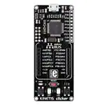
Kinetis clicker is an amazingly compact starter development kit which
brings the innovative mikroBUS™ socket to your favorite
microcontroller. It features MK22FN512VLH12, a 32-bit ARM®
Cortex®-M4 microcontroller, two indication LEDs, two general
purpose buttons, a reset button, a Micro USB connector and a single
mikroBUS™ socket. A JTAG connector and pads for interfacing with
external electronics are provided as well. The mikroBUS™ connector
consists of two 1x8 female headers with SPI, I2C, UART, RST, PWM,
Analog and Interrupt lines as well as 3.3V, 5V and GND power lines.
Kinetis clicker board can be powered over a USB cable.
Kinetis clicker
Contents
◾
◾
◾
◾
◾
1
2
3
4
5
Schematic
What’s onboard
Power supply
MK22FN512VLH12 microcontroller
Programming
◾ 5.1 Programming with mikroBootloader
◾ 5.2 Programming with mikroProg™ programmer
◾ 6 Oscillators
◾ 7 Buttons and LEDs
◾ 8 Resources
Kinetis clicker
IC/Module MK22FN512VLH12
(http://cache.nxp.com/files/microcontrollers/doc/data_sheet/K22P121M120SF7.pdf)
Interface
2 x mikroBUS™ sockets and 2x 26 pinout on board edges
Power
3.3V, 5V
supply
Schematic
Website
www.mikroe.com/kinetis/clicker (http://www.mikroe.com/kinetis/clicker)
Schematic also available as printable PDF (http://cdn-docs.mikroe.com/images/4/4a/Kinetis_clicker_v101_schematic.pdf)
What’s onboard
1. Micro USB connector
�Page 2 of 3
2.
3.
4.
5.
6.
7.
8.
9.
10.
11.
3.3V Voltage regulator
SWD/JTAG programmer connector
GPIO pinout
Kinetis MCU
8 MHz Crystal
mikroBUS™ socket
RESET button
Power Indication LED
Push buttons
LEDs
Power supply
When the board is powered up the power indication LED will be automatically turned on. The USB connection can provide up to 500mA of current which is
more than enough for the operation of all on-board and additional modules.
MK22FN512VLH12 microcontroller
The Kinetis clicker development tool comes with the MK22FN512VLH12 microcontroller. This 32-bit high performance microcontroller is rich with on-chip
peripherals and features 1024KB of Flash and 192KB of SRAM. It has integrated full speed USB 2.0. support.
Key microcontroller features:
◾
◾
◾
◾
◾
◾
◾
Up to 120 MHz operation (1.25 Dhrystone MIPS per MHz)
32-bit ARM® Cortex®-M4 architecture
512KB of Flash memory
128KB RAM
2x SAR 16-bit ADC, 2x 12-bit DAC
Two crystal oscillators: 32 kHz (RTC) and 32-40 kHz or 3-32 MHz
USB OTG, 3x UART, 2x I2C, 2x SPI, etc.
Programming
The microcontroller can be programmed in two ways:
1) Using USB HID mikroBootloader, 2) Using external mikroProg™ for Kinetis programmer.
Programming with mikroBootloader
You can program the microcontroller with a bootloader which is preprogrammed by default.
To transfer .hex file from a PC to MCU you need bootloader software (mikroBootloader USB HID) which can be downloaded from:
www.mikroe.com/kinetis/clicker-2
After the mikroBootloader software is downloaded, unzip it to desired location and start it.
step 1 – Connecting Kinetis clicker
To start, connect the USB cable, or if already connected press the Reset button on your Kinetis clicker. Click the Connect button within 5s to enter the
bootloader mode, otherwise existing microcontroller program will execute.
step 2 – Browsing for .HEX file
Click the Browse for HEX button and from a pop-up window choose the .HEX file which will be uploaded to MCU memory.
step 3 – Selecting .HEX file
Select .HEX file using open dialog window.
Click the Open button.
step 4 – Uploading .HEX file
To start .HEX file bootloading click the Begin uploading button.
Progress bar enables you to monitor .HEX file uploading.
step 5 – Finish upload
Click OK button after the uploading process is finished. Press Reset button on Kinetis clicker board and wait for 5 seconds. Your program will run
automatically.
�Page 3 of 3
Programming with mikroProg™ programmer
The microcontroller can be programmed with external mikroProg™ for Kinetis programmer and mikroProg Suite™ for ARM® software. The external
programmer is connected to the development system via 2x5 JTAG connector soldered on the CN3(TKDARKO) connector pads.
mikroProg™ is a fast USB 2.0 programmer with hardware debugger support. Outstanding performance, easy operation and elegant design are its key features.
mikroProg Suite™ for ARM® has an intuitive interface and programming technology. First, download the software from MikroElektronika's webpage
(http://www.mikroe.com/downloads/get/1809/mikroprog_suite_for_arm_v132.zip).
After downloading, extract the package and double click the executable setup file, to start the installation.
Click the Detect MCU button in order to recognize the device ID. Click the Read button to read the entire microcontroller memory. You can click the Save
button to save it to the target HEX file.
If you want to write the HEX file into the microcontroller, first make sure to load the target HEX file using the Load button. Then click the Write button to begin
programming. Click the Erase button to clear the microcontroller memory.
Oscillators
The MK22FN512VLH12 microcontroller is equipped with internal 32 kHz, 4 MHz and 48 MHz references that provide a stable clock signal. Since the chips
have an integrated PLL, this base frequency is suitable for further clock multiplication. The board also contains an additional 8MHz crystal oscillator, as well as
a 32.768kHz one, which provides an external clock for the internal RTCC module.
Buttons and LEDs
The board also contains a 01 reset button and a pair of 02 buttons and 03 LEDs. Each of these additional peripherals are located in the bottom area of the board.
Reset button is used to manually reset the microcontroller. Pressing the reset button will generate a low voltage level on microcontroller’s reset pin. LEDs can be
used for visual indication of the logic state on two pins (RA0 and RA1). An active LED indicates that a logic high (1) is present on the pin. Pressing any of these
buttons can change the logic state of the microcontroller pins (RD2 and RD3) from logic high (1) to logic low (0)
Resources
- Kinetis MK22FN512VLH12 data sheet (http://cache.nxp.com/files/microcontrollers/doc/data_sheet/K22P121M120SF7.pdf)
- mikroProg Suite for ARM direct download (http://www.mikroe.com/downloads/get/1809/mikroprog_suite_for_arm_v132.zip)
- USB HID bootloader for Kinetis clicker (http://www.mikroe.com/downloads/get/2574/kinetis-clicker-bootloader.rar)
- Kinetis K22 overview on NXP.com (http://www.nxp.com/products/microcontrollers-and-processors/arm-processors/kinetis-cortex-m-mcus/k-seriesperformance-m4/k2x-usb/kinetis-k22-120-mhz-cost-effective-full-speed-usb-microcontrollers-mcus-based-on-arm-cortex-m4-core:K22_120)
Retrieved from "http://docs.mikroe.com/index.php?title=Kinetis_clicker&oldid=437"
◾ This page was last modified on 20 June 2016, at 18:20.
◾ Content is available under Creative Commons Attribution unless otherwise noted.
http://docs.mikroe.com/index.php?title=Kinetis_clicker&printable=yes
7/11/2016
�
很抱歉,暂时无法提供与“MIKROE-2330”相匹配的价格&库存,您可以联系我们找货
免费人工找货- 国内价格 香港价格
- 1+414.987121+53.68967
- 国内价格
- 1+393.62222
- 5+385.74936