Mikromedia 7 for STM32F7
1
Mikromedia 7 for STM32F7
mikromedia 7 for STM32F7
mikromedia 7 for STM32F7
IC/Module
Interface
STM32F746ZG
[1]
1x 26 pinout on board edges
Power supply 3.3V
Website
Schematic
www.mikroe.com/mikromedia/7/stm32f7/
PDF schematic
[2]
[3]
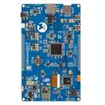
mikromedia 7 for STM32F7 is a compact development system with lots of on-board peripherals which allow
development of devices with multimedia contents. The central part of the system is a 32-bit ARM® Cortex™-M4
STM32F746ZG 144-pin microcontroller.
The mikromedia 7 for STM32F7 features integrated modules such as stereo MP3 codec, 7” TFT 800x480 touch
screen display. The increased screen size is ideal for displaying larger amounts of data.
The board also contains an accelerometer, microSD card slot, buzzer, IR receiver, RGB LED diode, PIN photodiode,
temperature sensor, 2.4GHz RF, WiFi, Ethernet and CAN transceivers, 8 Mbit flash memory, RTC battery,
Li-Polimer battery charger, etc.
Additional components include MINI-B USB connector, power screw terminals, 2x5 JTAG connector, two 1x26
connection pads, ON/OFF switch and other. It comes with an onboard mikroProg™ for STM32 programmer and
debugger, but can also be programmed with external programmers, such as ST-LINK programmer.
�Mikromedia 7 for STM32F7
Power Supply
The mikromedia 7 for STM32F7 board can be powered in four different ways: via two USB connectors using
MINI-B USB cable provided with the board (CN4 or CN11), via battery connector using Li-Polymer battery (CN5)
or via adapter connector using adapter power supply (CN3). After you plug in the appropriate power supply turn the
power switch ON (SW1). The USB connection can provide up to 500mA of current which is more than enough for
the operation of all on-board modules and the microcontroller as well. If you decide to use external power supply via
screw terminals, voltage values must be within 5-12V DC range. Power LED ON (GREEN) indicates the presence of
power supply. On-board battery charger circuit MCP73832 enables you to charge the battery over USB connection
or via screw terminals. LED diode (RED) indicates when battery is charging. Charging current is ~250mA and
charging voltage is 4.2V DC.
STM32F746ZG microcontroller
The mikromedia 7 for STM32F7 development board comes with the 144-pin ARM® Cortex™-M7 STM32F746ZG
microcontroller. This high-performance 32-bit microcontroller with its integrated modules and in combination with
other onboard modules is ideal for multimedia applications
2
�Mikromedia 7 for STM32F7
Key microcontroller features
•
•
•
•
•
•
•
•
Up to 462 DMIPS Operation (216 MHz);
1 MB of Flash memory;
320 + 64 KB of SRAM memory;
up to 140 I/O pins;
16/32-bit timers
16MHz internal oscillator, 32kHz RTCC, PLL;
4xUART, 3xSPI, 3xI2C, 2xCAN, 3xADC, 3XADC etc.
Ethernet, USB etc.
Programming the microcontroller
The microcontroller can be programmed in two ways:
1. Using onboard mikroProg™ for STM32 programmer
2. Using external programmers for STM32 (like ST-LINK)
Using mikroProg™ programmer
The microcontroller can be programmed with onboard mikroProg™ for STM programmer and mikroProg Suite™
for ARM® software. Connection with PC is established over an PROG USB connector. For proper insertion of the
MINI-B USB cable. Signalization LED (LINK) is also provided on the opposite side of the PROG USB connector. It
is also possible to program the microcontroler with external porogrammers, via 2x5 JTAG connector (CN1) with an
appropriate adapter.
3
�Mikromedia 7 for STM32F7
mikroProg Suite™ for ARM® software
mikroProg™ for STM32 programmer requires special programming software called mikroProg Suite™ for ARM®.
This software is used for programming ALL of STM32 ARM® Cortex-M3™ and Cortex-M7™ microcontroller
families. It features intuitive interface and SingleClick™ programming technology. Software installation is available
on following link:
www.mikroe.com/downloads/get/1809/mikroprog_suite_for_arm.zip [4]
After downloading, extract the package and double click the executable setup file to start installation.
Software Installation wizard
The board is equipped with reset button, which is located on the front side of the board. If you want to reset the
circuit, press the reset button. It will generate low voltage level on the microcontroller reset pin (input). A reset can
also be externally provided through the pin 26 on the side headers.
4
�Mikromedia 7 for STM32F7
RTC Battery and Rest Button
Reset Button
The board is equipped with reset button, which is located on the front side of the board. If you want to reset the
circuit, press the reset button. It will generate low voltage level on the microcontroller reset pin (input). A reset can
also be externally provided through the pin 26 on the side headers.
RTC Battery
mikromedia 7 for STM32F7 features an RTC battery holder for microcontroller RTC module. Battery is used as
alternate source of power, so the RTC module can continue to keep time while the primacy source of power is off or
currently unavailable. Three types of coin battery are supported: CR1216, CR1220 and CR1225.
Crystal oscillators and 2.048V reference
The board is equipped with 1 25MHz crystal oscillator (X5) circuit that provides external clock waveform to the
microcontroller OSCO and OSCI pins. This base frequency is suitable for further clock multipliers and ideal for
generation of necessary USB clock, which ensures proper operation of bootloader and your custom USB-based
applications. The board also contains 2 32.768 kHz crystal oscillator (X4) which provides external clock for internal
RTCC module. Microcontroller ADC requires an accurate source of reference voltage signal. That is why we
provide the external 3 voltage reference to the microcontroller VREF pin which is 2.048V.
5
�Mikromedia 7 for STM32F7
microSD Card Slot
Board contains 1 microSD card slot for using 2 microSD cards in your projects. It enables you to store large amounts
of data externally, thus saving microcontroller memory. microSD cards use Serial Peripheral Interface (SPI) for
communication with the microcontroller. Ferrite and capcitor are provided to compensate the voltage and current
glitch that can occur when pushing-in and pushing-out microSD card into the socket. Proper insertion of the
microSD card is shown in the image above.
This code snippet initializes the FAT32 library for usage with SD card:
void char Init_FAT(){
char FAT_cnt = 0;
if (MMC_Card_Detect == 0){
if (Fat_Initialized_Flag == 0){
while ((Fat32_Init() != 0) && (FAT_cnt < 5))
Fat_cnt ++;
if (FAT_cnt < 5){
SDIO_Init(_SDIO_CFG_POWER_SAVE_DISABLE |
_SDIO_CFG_4_WIDE_BUS_MODE | _SDIO_CFG_CLOCK_BYPASS_DISABLE
| _SDIO_CFG_CLOCK_RISING_EDGE |
_SDIO_CFG_HW_FLOW_DISABLE, 1, &_GPIO_MODULE_SDIO_D0_D3);
Fat_Initialized_Flag = 1;
}
}
if (Ext_res_initialized == 0){
TFT_Set_Ext_Buffer(MyTFT_Get_Data);
Ext_fhandle = FAT32_Open("Ext_reso.RES", 1);
if (Ext_fhandle != 0xFF)
Ext_res_initialized = 1;
}
}
6
�Mikromedia 7 for STM32F7
return Ext_res_initialized;
}
Touch Screen
The development system features a 7‘‘ TFT 800x480 display covered with a resistive touch panel. Together they
form a functional unit called a touch screen. It enables data to be entered and displayed at the same time. The TFT
display is capable of showing graphics in 262K different colors.
For example here is how to programm the SSD1963 display driver to trigger the Fade-in effect on the display:
void BLED_Fade_In(){
int i;
for (i = 1; i < 255; i++){
TFT_Set_DBC_SSD1963(i);
Delay_ms(1);
}
TFT_Set_DBC_SSD1963(255);
}
This is the callibration routine for the touchscreen controller:
void Calibrate() {
TFT_Fill_Screen(CL_BLACK);
TFT_Set_Font(TFT_defaultFont, CL_WHITE, FO_HORIZONTAL);
STMPE610_ClearInterruptFlagsAndFIFO();
TFT_Set_Brush(1, CL_WHITE, 0, 0, 0, 0);
TFT_Circle(0, 0, 3);
STMPE610_CalibratePoint(STMPE610_FIRST_CORNER);
7
�Mikromedia 7 for STM32F7
Delay_ms(500);
TFT_Set_Brush(1, CL_BLACK, 0, 0, 0, 0);
TFT_Circle(0, 0, 3);
STMPE610_ClearInterruptFlagsAndFIFO();
TFT_Set_Brush(1, CL_WHITE, 0, 0, 0, 0);
TFT_Circle(0, TFT_DISP_HEIGHT-1, 3);
STMPE610_CalibratePoint(STMPE610_SECOND_CORNER);
Delay_ms(500);
TFT_Set_Brush(1, CL_BLACK, 0, 0, 0, 0);
TFT_Circle(0, TFT_DISP_HEIGHT-1, 3);
STMPE610_ClearInterruptFlagsAndFIFO();
TFT_Set_Brush(1, CL_WHITE, 0, 0, 0, 0);
TFT_Circle(TFT_DISP_WIDTH-1, TFT_DISP_HEIGHT-1, 3);
STMPE610_CalibratePoint(STMPE610_THIRD_CORNER);
Delay_ms(500);
TFT_Set_Brush(1, CL_BLACK, 0, 0, 0, 0);
TFT_Circle(TFT_DISP_WIDTH-1, TFT_DISP_HEIGHT-1, 3);
STMPE610_ClearInterruptFlagsAndFIFO();
TFT_Set_Brush(1, CL_WHITE, 0, 0, 0, 0);
TFT_Circle(TFT_DISP_WIDTH-1, 0, 3);
STMPE610_CalibratePoint(STMPE610_FOURTH_CORNER);
TFT_Set_Brush(1, CL_BLACK, 0, 0, 0, 0);
TFT_Circle(TFT_DISP_WIDTH-1, 0, 3);
Delay_ms(500);
}
Audio Module
8
�Mikromedia 7 for STM32F7
mikromedia 7 for STM32F7 features stereo audio codec 1 VS1053. This module enables audio reproduction and
sound recording by using 2 stereo headphones with microphone connected to the system via a 3 3.5mm connector
(CN2). All functions of this module are controlled by the microcontroller over Serial Peripheral Interface (SPI). IN
and OUT channels are also provided on side headers (HDR2).
This is the function to start playing a chosen MP3 file from the SD card:
void MP3_play(char *Song_Name, char File_No){
current_file = File_No;
Buffer_count = 0;
current_fhandle = FAT32_Open(Song_Name, FILE_READ);
FAT32_Size(Song_Name, &file_size);
Buffer_count = 0;
Total_Buffers = File_size / BUFFER_SIZE;
MP3_Reset_Time();
MP3_Check_Time();
MP3_Set_Volume(100 - level, 100 - level);
UpdateVolumeBar( level, 0);
MP3_Example_State = 2;
}
USB DEVICE connection
ARM® Cortex™-M7 STM32F746ZG microcontroller has integrated USB module, which enables you to implement
USB communication functionality to your mikromedia board. Connection with target USB host is establish over 1
MINI-B USB connector. For proper insertion of the 2 MINI-B USB see image above.
9
�Mikromedia 7 for STM32F7
USB HOST connection
mikromedia 7 for STM32F7 can also be used as USB HOST which enables microcontroller to establish a connection
with the target device (eg. USB keyboard, USB mouse, etc). The board provides necessary power supply to the
target via TPS2041B IC. In order to enable the 1 USB HOST cable to be connected to the board, it is necessary to
use the appropriate 2 MINI-B USB to USB type A adapter.
Accelerometer
Onboard ADXL345 accelerometer is used to measure acceleration in three axis: x, y and z. The accelerometer
function is defined by the user in the program loaded into the microcontroller. Communication between the
accelerometer and the microcontroller is performed via the I 2 C interface. There is an option to select the alternate
accel address with jumper J3.
The following function reads 16 measurement samples from the accelerometer and returns the average value:
static void Accel_Average() {
int i, sx, sy, sz, xx, yy, zz;
// sum
sx = sy = sz = 0;
// average accelerometer reading over last 16 samples
for (i=0; i= 1000)
Light_Intensity = 1000;
WordToStr(Light_Intensity, text);
ptr1 = text;
ptr2 = Diagram5_Label4_Caption;
while (*ptr1){
if (*ptr1 != ' ')
*ptr2++ = *ptr1;
ptr1++;
}
ptr2--;
temp = *ptr2;
*ptr2++ = '.';
*ptr2++ = temp;
*ptr2++ = ' ';
*ptr2++ = '%';
*ptr2 = 0;
RedrawLabel(Diagram5_Box1.Color, &Diagram5_Label4, 240, 90);
return Light_Intensity;
}
This function displays color provided as an argument on RGB led:
static void Drive_RGB_Diode(TColors *colors){
PWM_TIM2_Set_Duty((int)pwm_period2 / 64 * colors->Green,
_PWM_NON_INVERTED, _PWM_CHANNEL2);
PWM_TIM3_Set_Duty((int)pwm_period1 / 32 * colors->Blue,
_PWM_NON_INVERTED, _PWM_CHANNEL1);
SoftPWM_duty = colors->Red;
}
17
�Mikromedia 7 for STM32F7
Pads
Many microcontroller pins are available for further connectivity via two 1x26 rows of connection pads on both sides
of the board. They are designed to match with mikromedia 7 SHIELD for STM32F746ZG.
What’s next?
You have now completed the journey through each and every feature of mikromedia 7 for STM32F4 board. You got
to know its modules and organization. Now you are ready to start using your new board. We are suggesting several
steps which are probably the best way to begin. Find useful projects and tutorials on the Libstock website
(www.libstock.com [5]). Join our Forum (www.mikroe.com/forum [6]) and get help from a large ecosystem of users.
18
�Mikromedia 7 for STM32F7
Compiler
You still don’t have an appropriate compiler? Locate ARM® compiler that suits you best on our website:
www.mikroe.com/arm/compilers [7] Choose between mikroC™, mikroBasic™ and mikroPascal™ and download a
fully functional demo version, so you can start building your first applications.
Visual TFT
Once you have chosen your compiler, and since you already got the board, you are ready to start writing your first
projects. Visual TFT software enables you to quickly create your GUI. It will automatically generate code
compatible with MikroElektronika compilers. Visual TFT is rich with examples, which are an excellent starting
point for your future projects. Download it from www.mikroe.com/visualtft [8]
Resources
• mikromedia 7 for STM32F7 landing page [9]
• mikroProg for STM32 drivers download [10]
• mikromedia for STM32F7 Libstock example [11]
References
[1] http:/ / www. st. com/ content/ ccc/ resource/ technical/ document/ datasheet/ 96/ ed/ 61/ 9b/ e0/ 6c/ 45/ 0b/ DM00166116. pdf/ files/
DM00166116. pdf/ jcr:content/ translations/ en. DM00166116. pdf
[2] http:/ / www. mikroe. com/ mikromedia/ 7/ stm32f7
[3] http:/ / cdn-docs. mikroe. com/ images/ a/ a9/ Mikromedia_7_stm32_schematic. pdf
[4] http:/ / www. mikroe. com/ downloads/ get/ 1809/ mikroprog_suite_for_arm. zip
[5] http:/ / www. libstock. com
[6] http:/ / www. mikroe. com/ forum
[7] http:/ / www. mikroe. com/ arm/ compilers
[8] http:/ / www. mikroe. com/ visualtft
[9] http:/ / www. mikroe. com/ mikromedia/ 7/ stm32f7/
[10] http:/ / www. mikroe. com/ downloads/ get/ 2444/ st_link_v2_usb_driver. zip
[11] http:/ / libstock. mikroe. com/ projects/ view/ 1926/ mikromedia-7-for-stm32f7
19
�Article Sources and Contributors
Article Sources and Contributors
Mikromedia 7 for STM32F7 Source: http://docs.mikroe.com/index.php?oldid=1676 Contributors: Andrea.galizia, Srdjan.misic
Image Sources, Licenses and Contributors
File:Mikromedia-7-stm32f7.jpg Source: http://docs.mikroe.com/index.php?title=File:Mikromedia-7-stm32f7.jpg License: unknown Contributors: Srdjan.misic
file:M7-2.jpg Source: http://docs.mikroe.com/index.php?title=File:M7-2.jpg License: unknown Contributors: Srdjan.misic
file:M7-4.jpg Source: http://docs.mikroe.com/index.php?title=File:M7-4.jpg License: unknown Contributors: Srdjan.misic
file:M7-5.jpg Source: http://docs.mikroe.com/index.php?title=File:M7-5.jpg License: unknown Contributors: Srdjan.misic
file:M7-8.jpg Source: http://docs.mikroe.com/index.php?title=File:M7-8.jpg License: unknown Contributors: Srdjan.misic
file:M77-9.jpg Source: http://docs.mikroe.com/index.php?title=File:M77-9.jpg License: unknown Contributors: Srdjan.misic
file:M7-12.jpg Source: http://docs.mikroe.com/index.php?title=File:M7-12.jpg License: unknown Contributors: Srdjan.misic
file:M7-14.jpg Source: http://docs.mikroe.com/index.php?title=File:M7-14.jpg License: unknown Contributors: Srdjan.misic
file:M7-16.jpg Source: http://docs.mikroe.com/index.php?title=File:M7-16.jpg License: unknown Contributors: Srdjan.misic
file:M7-18.jpg Source: http://docs.mikroe.com/index.php?title=File:M7-18.jpg License: unknown Contributors: Srdjan.misic
file:M7-20-1.jpg Source: http://docs.mikroe.com/index.php?title=File:M7-20-1.jpg License: unknown Contributors: Srdjan.misic
file:M7-24.jpg Source: http://docs.mikroe.com/index.php?title=File:M7-24.jpg License: unknown Contributors: Srdjan.misic
file:M7-26.jpg Source: http://docs.mikroe.com/index.php?title=File:M7-26.jpg License: unknown Contributors: Srdjan.misic
file:M7-28.jpg Source: http://docs.mikroe.com/index.php?title=File:M7-28.jpg License: unknown Contributors: Srdjan.misic
file:M77-30.jpg Source: http://docs.mikroe.com/index.php?title=File:M77-30.jpg License: unknown Contributors: Srdjan.misic
File:M7-32.jpg Source: http://docs.mikroe.com/index.php?title=File:M7-32.jpg License: unknown Contributors: Srdjan.misic
file:M77-34.jpg Source: http://docs.mikroe.com/index.php?title=File:M77-34.jpg License: unknown Contributors: Srdjan.misic
file:M77-36.jpg Source: http://docs.mikroe.com/index.php?title=File:M77-36.jpg License: unknown Contributors: Srdjan.misic
file:M77-38.jpg Source: http://docs.mikroe.com/index.php?title=File:M77-38.jpg License: unknown Contributors: Srdjan.misic
File:Mikromedia-7-stm32f7-pinout.jpg Source: http://docs.mikroe.com/index.php?title=File:Mikromedia-7-stm32f7-pinout.jpg License: unknown Contributors: Srdjan.misic
file:M77-42.jpg Source: http://docs.mikroe.com/index.php?title=File:M77-42.jpg License: unknown Contributors: Srdjan.misic
License
Creative Commons Attribution
https:/ / creativecommons. org/ licenses/ by/ 4. 0/
20
�