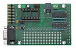
BASIC Stamp Controller Interface Board
REV B
27945
BASIC Stamp Controller Interface Board:
Features and Specification
The BASIC Stamp Controller Interface Board (StampCI) is intended for direct connection of Parallax BASIC Stamp
microcontroller (BS1-IC, BS2-IC, BS2e-IC, BS2sx-IC and BS2p24-IC modules) to industrial digital I/O controllers with
50 pin IDC type connector interface. This documentation explains StampCI features.
Features
•
•
•
•
•
•
•
•
Supports either BS1-IC, BS2-IC, BS2e-IC, BS2sx-IC and BS2p24-IC
2.1mm power plug
+5vdc 1000ma power output for digital I/O controller
Prototype area for connection of peripheral devices to BASIC Stamp I/O pins
PC parallel and serial ports for programming the BS1-IC, BS2-IC, BS2e-IC, BS2sx-IC and BS2p24-IC respectively
BASIC Stamp I/O pin connections to PC parallel port I/O pins
0 to 70 °C operating temperature range
Built in DB 9 connector for easy interface to PC
Power Supply
Power required is 9-12 vdc @ 1000ma max. The green LED should light when power is applied. Please note that the
center tap on the 2.1mm power plug must be a positive (+) connection. Ground for the relay rack will be supplied
through the 50 pin header. There is also a ground accessible on the (x3) screw-down terminal on the termnal that is
furthest away from the +5 indicator on the broad. Always disconnect the external power source from the board before
attempting to install or remove any board components.
BASIC Stamp Modules
The StampCI board allows you to use the BS1-IC, BS2-IC, BS2e-IC, BS2sx-IC and BS2p24-IC modules. Never install
more than one of these modules on the board. The module’s pin 1 connects to the number 1 marking on the board.
Modules may also be programmed while connected to the StampCI board.
Reset Switch
The reset switch is common to all BASIC Stamps. Each BASIC Stamp has its own brown-out-reset circuit that pulls the
reset line high. Pushing the reset pushbutton pulls the RST line of the BASIC Stamp to ground, thereby resetting the
BASIC Stamp. The same thing can be done through the PC parallel port (x1) pin 1 by setting it low and returning to a
high state. NOTE: (If pin 1 of port x1 pin is driven high, the BASIC Stamp will not be able to be reprogrammed). A
ribbon cable can be connected to an IDC header with the opposite side attached to a DB25 connector to provide a
parallel connection between the PC and header connector (x1).
sales / technical support (916) 624-8333 • fax (916) 624-8003
stamptech@parallaxinc.com
Date 3/01
v1.2
Page 1
�BASIC Stamp Controller Interface Board
REV B
BS1-IC Programming Interface
The BS1-IC programming interface is a 3 pin, in-line connection (x2). When connecting the BS1-IC Programming Cable
(provided in either the BS1-IC Starter Kit or the Stamp Programming Package) line up the arrow found on the side of
the cable with the arrows found on the StampCI board next to the x2 connector.
BS2-IC, BS2e-IC, BS2sx-IC and BS2p24-IC Programming Interface
The BS2-IC, BS2e-IC, BS2sx-IC and BS2p24-IC programming interface is the built-in DB 9 connector. Use a standard,
straight-through serial cable (not a null-modem cable). The cable that is provided in the BS2 (or above) starter kit is
perfect for this.
Rev B
+5
Host Parallel Port
BS2
STAMPCI ©2000
BS1
Reset
P1
+5V P0
P3
P2
P5
P4
P7
P6
P9 P11 P13 P15
P8 P10 P12 P14
+5V
Gnd
Gnd
Stamp CI with BS1-IC properly installed.
Rev B
+5
Host Parallel Port
BS2
STAMPCI ©2000
BS1
Reset
P1
+5V P0
P3
P2
P5
P4
P7
P6
P9 P11 P13 P15
P8 P10 P12 P14
Gnd
+5V
Gnd
Stamp CI with BS2-IC properly installed.
sales / technical support (916) 624-8333 • fax (916) 624-8003
stamptech@parallaxinc.com
Date 3/01
v1.2
Page 2
�BASIC Stamp Controller Interface Board
REV B
I/O Pins
All of the BASIC Stamp's I/O pins connect directly to the prototype area of the board with no driver protection. When
hooking devices to the BASIC Stamp from the prototype board, care must be taken to ensure you follow the current
and voltage specifications of the BASIC Stamp module that you are using. The BASIC Stamp's I/O pins are also
connected to the 50-pin header through a ULN2803a that is set up as an open collector line driver.
Software Programming
Simply use the BASIC Stamp’s HIGH or LOW command to turn the digital I/O module on or off. The Stamp CI board
can be programmed with the Windows or Dos software provided in the Starter Kit or on the Parallax, Inc web site:
http://www.parallaxinc.com. There is also a VB program that allows users to view the I/O ports on their PC via parallel
port. This software can also be found at the Parallax web site.
Controller Board Interface
The StampCI board’s 50-pin IDC header (x4) attaches directly to the mating pin IDC header of the digital I/O control
board (OPTO22 p/n G4PB16 or equivalent digital I/O board that has the same connector electrical layout). The boards
are attached on the same level to one another.
sales / technical support (916) 624-8333 • fax (916) 624-8003
stamptech@parallaxinc.com
Date 3/01
v1.2
Page 3
�BASIC Stamp Controller Interface Board
REV B
NC
P0
P1
P2
P3
P4
P5
P6
P7
P6
P7
P8
P9
P10
P11
P12
P13
P14
P15
NC
NC
NC
NC
NC
NC
1
VSS
X4
Top view
sales / technical support (916) 624-8333 • fax (916) 624-8003
stamptech@parallaxinc.com
Date 3/01
v1.2
Page 4
�
很抱歉,暂时无法提供与“27945”相匹配的价格&库存,您可以联系我们找货
免费人工找货