LPCXpresso Experiment Kit - User’s Guide
Copyright 2013 © Embedded Artists AB
LPCXpresso Experiment Kit
User’s Guide
Learn embedded programming with NXP’s LPC1000
family of Cortex-M0/M3 microcontrollers!
EA-USG-1206 Rev A
�LPCXpresso Experiment Kit - User’s Guide
Page 2
Embedded Artists AB
Davidshallsgatan 16
211 45 Malmö
Sweden
info@EmbeddedArtists.com
http://www.EmbeddedArtists.com
Copyright 2013 © Embedded Artists AB. All rights reserved.
No part of this publication may be reproduced, transmitted, transcribed, stored in a retrieval system, or
translated into any language or computer language, in any form or by any means, electronic,
mechanical, magnetic, optical, chemical, manual or otherwise, without the prior written permission of
Embedded Artists AB.
Disclaimer
Embedded Artists AB makes no representation or warranties with respect to the contents hereof and
specifically disclaim any implied warranties or merchantability or fitness for any particular purpose.
Information in this publication is subject to change without notice and does not represent a
commitment on the part of Embedded Artists AB.
Feedback
We appreciate any feedback you may have for improvements on this document. Please send your
comments to support@EmbeddedArtists.com.
Trademarks
All brand and product names mentioned herein are trademarks, services marks, registered
trademarks, or registered service marks of their respective owners and should be treated as such.
Copyright 2013 © Embedded Artists AB
�LPCXpresso Experiment Kit - User’s Guide
Page 3
Table of Contents
1 Document Revision History
7
2 Introduction
8
2.1
Features
8
2.2
ESD Precaution
9
2.3
General Handling Care
9
2.4
Code Read Protection
9
2.5
CE Assessment
9
2.6
Other Products from Embedded Artists
9
2.6.1
Design and Production Services
2.6.2
OEM / Evaluation / QuickStart Boards and Kits
3 LPCXpresso Experiment Kit
3.1
Embedded Systems Programming
10
11
12
4 Kit Content
13
5 Powering Options
25
6 Soldering
27
6.1
Component Placement
7 Experiments
27
29
7.1
Preparation
29
7.2
Control a LED
29
7.2.1
Lab 1a: Control LED
30
7.2.2
Lab 1b: GPIO and Bit Masking
35
7.2.3
Lab 1c: Delay Function – LED Flashing
36
7.2.4
Lab 1d: Morse Code
37
7.3
Read a Digital Input
38
7.3.1
Lab 2a: Read Push-button
38
7.3.2
Lab 2b: GPIO and Bit Masking
41
7.3.3
Lab 2c: Logic between inputs and output
41
7.3.4
Lab 2d: Toggling LED
44
7.3.5
Lab 2e: Sampling of Inputs
44
7.4
Control Multiple LEDs
46
7.4.1
Lab 3a: LEDs in Running-One Pattern
46
7.4.2
Lab 3b: Control of Running-One Pattern
47
7.4.3
Lab 3c: Rotary Switch Control of Running-One Pattern
48
7.5
Copyright 2013 © Embedded Artists AB
9
Print Messages
49
7.5.1
Lab 4a: Semihosting and printf()
49
7.5.2
Lab 4b: Semihosting Performance Test
51
7.5.3
Lab 4c: Printing Events
51
7.5.4
Lab 4d: Reading from the Console
51
�LPCXpresso Experiment Kit - User’s Guide
Page 4
7.6
53
7.6.1
Lab 5a: Read Trimming Potentiometer
53
7.6.2
Lab 5b: Event Threshold
56
7.6.3
Lab 5c: Read Light Sensor
56
7.6.4
Lab 5d: ADC Noise Test
57
Pulse Width Modulation
58
7.7
7.7.1
Lab 6a: PWM Control of a LED
58
7.7.2
Lab 6b: PWM Control of a LED, cont. 1
59
7.7.3
Lab 6c: PWM Control of a LED, cont. 2
59
7.7.4
Lab 6d: PWM Control of two LEDs
60
7.8
Control an RGB-LED
61
7.8.1
Lab 7a: Test RGB-LED
61
7.8.2
Lab 7b: Control RGB-LED
62
Control a 7-segment Display
63
7.9
7.9.1
Lab 8a: Test 7-segment Display
64
7.9.2
Lab 8b: Control 7-segment Display
64
7.9.3
Lab 8c: Control 7-segment Display, cont.
66
7.9.4
Lab 8d: Control Dual Digit 7-segment Display
66
7.9.5
Lab 8e: Control 7-segment Display via Shift Register
68
7.10
Work with a Timer
71
7.10.1
7.11
Lab 9a: Create Exact Delay Function
PWM via a Timer
71
72
7.11.1
Lab 10a: Control RGB-LED
74
7.11.2
Lab 10b: Buzzer and Melodies
74
7.11.3
Lab 10c: Control a Servo Motor
75
7.12
Work with a Serial Bus – SPI
78
7.12.1
Lab 11a: Access Shift Register
81
7.12.2
Lab 11b: Control 7-segment Display
82
7.12.3
Lab 11c: Access SPI E2PROM
82
7.13
Work with Interrupts
87
7.13.1
Lab 12a: Generate IRQ via GPIO
89
7.13.2
Lab 12b: Timer IRQ
90
7.13.3
Lab 12c: Timer IRQ with Callback
91
7.13.4
Lab 12d: Nested Interrupts
92
7.13.5
Lab 12e: Control Dual Digit 7-segment Display
93
7.14
Work with a Serial Bus – I2C
94
7.14.1
Lab 13a: Solder Surface Mounted Components
95
7.14.2
Lab 13b: Read LM75 Temperature Sensor
96
7.14.3
Lab 13c: Control LEDs via PCA9532
97
7.15
Work with a Serial Bus – UART
100
7.15.1
Lab 14a: Transmitting and Receiving via the UART
106
7.15.2
Lab 14b: Direct printf() to UART
106
7.15.3
Lab 14c: Interrupt driven UART handling and ring buffers
107
7.16
Copyright 2013 © Embedded Artists AB
Read an Analog Input
Extra: Work with RF-module
112
7.16.1
Lab 15a: XBee™ RF-Module
113
7.16.2
Lab 15b: GPS Receiver
117
�LPCXpresso Experiment Kit - User’s Guide
Page 5
7.17
7.17.1
7.18
Extra: Work with Serial Expansion Connector
123
Lab 16a: 128x128 OLED Graphical Display
123
Extra: Work with USB Device
126
7.18.1
Lab 17a: USB Device – HID
126
7.18.2
Lab 17b: USB Device – Mouse HID
127
7.19
7.19.1
7.20
Extra: Work with USB Host
Lab 18a: USB Host
Extra: Work with Ethernet Interface
128
129
7.20.1
Lab 19a: easyWeb Web Server
129
7.20.2
Lab 19b: lwIP TCP/IP Stack, Web Server and FreeRTOS
130
7.21
Differences between LPCXpresso LPC111x and LPC1114 in DIL28
8 Projects
133
135
8.1
Interface a Color Sensor
135
8.2
Interface a Real-time Clock (RTC)
135
8.3
Interface a GPS Module
135
8.4
Interface an SD/MMC Memory Card
135
8.5
Interface an Accelerometer and Gyro
135
8.6
Control a LED Matrix
136
8.7
Create a Game with Display + Accelerometer or Gyro
136
8.8
Create General Menu System for a Display
136
8.9
Retrieve Information from Web Servers
136
8.10
USB Mouse Emulation
136
8.11
Registry in E2PROM
137
8.12
Real-Time Dynamic Data with JAVA Applet
137
8.13
Multiplayer Game via RF-module
137
8.14
Home Alarm System
137
8.15
Polyphonic Audio Generation
138
8.16
Audio Processing
138
8.17
Home Automation
138
8.18
Control a Robot
138
8.19
RS-485 Network
138
8.20
Interface an FPGA/CPLD Chip
138
8.21
Analog Electronic Experiments
138
9 LPCXpresso IDE – How to get Started
139
9.1
Importing Projects
139
9.2
Working with a Project and Compiling
141
9.3
Debugging a Project and Downloading
142
9.3.1
Downloading Just Code
146
9.4
Create own Projects by Copy Existing Project
150
9.5
Common Problems
151
9.5.1
Copyright 2013 © Embedded Artists AB
128
Error message: Failed on chip setup
152
�LPCXpresso Experiment Kit - User’s Guide
Page 6
10 Further Information
Copyright 2013 © Embedded Artists AB
153
�LPCXpresso Experiment Kit - User’s Guide
Page 7
1 Document Revision History
Revision
Date
Description
PA1
2012-07-16
Work in progress.
PA2
2013-01-14
Work in progress.
PA3
2013-01-25
First version to be released. All experiments are still not complete.
PA4
2013-01-29
Minor corrections/clarifications.
PA5
2013-02-25
Completed section 7.9 - 7.10.
PA6
2013-03-19
Completed section 7.11-7.14. Cleanup in variable declarations in
code fragments. Added instructions about creating driver structured
source code.
PA7
2013-04-08
Completed section 7.15. Changed all code fragments to use
predefined typedefs for variable declaration. Minor corrections.
PA8
2013-06-13
Completed section 7.16-7.20. Minor corrections/clarifications.
Copyright 2013 © Embedded Artists AB
�LPCXpresso Experiment Kit - User’s Guide
Page 8
2 Introduction
Thank you for buying Embedded Artists’ LPCXpresso Experiment Kit designed to work with NXP’s
ARM Cortex-M0/M3 LPCXpresso target boards.
This document is a User’s Guide that describes the LPCXpresso Experiment Kit that describes
hardware as well as software related to the kit.
2.1
Features
The kit has been created as a guided tour to learn embedded programming with NXP’s LPC1000
microcontroller family with Cortex-M0/M3 cores from ARM. The experiments can be performed on a
breadboard for maximum flexibility and ease of use. It is also possible to solder the components to a
printed circuit board (pcb) and learn soldering at the same time.
Components included in the kit are:
8x LEDs
2x Trimming potentiometers
7x push-buttons
RGB-LED
Light sensor (analog)
Temperature sensor (analog)
7-segment LED, dual digit
E2PROM with SPI interface
Temperature sensor with I2C interface (only for pcb mounting)
Piezo buzzer
Rotary quadrature encoder (only for pcb mounting)
Shift register
I2C ports expander (PCA9532, only for pcb mounting)
USB Host connector (only for pcb mounting)
USB Device connector (only for pcb mounting)
RJ45 connector for Ethernet (only for pcb mounting)
14-pos serial expansion connector, for interface to for example graphical displays
3x servo connectors. Note that servos are not included.
XBee™ compatible socket (for ZigBee and WiFi modules). Note that RF module is not
included.
LPC1114 in DIL28 package, with 12MHz crystal and SWD connector (only for pcb mounting)
Local +3.3V voltage regulator
Miscellaneous resistors, capacitors, transistors and connectors
Breadboard with cables
Naked PCB
Copyright 2013 © Embedded Artists AB
�LPCXpresso Experiment Kit - User’s Guide
2.2
Page 9
ESD Precaution
Please note that the LPCXpresso Experiment Kit come without any case/box
and all components are exposed for finger touches – and therefore extra
attention must be paid to ESD (electrostatic discharge) precaution.
Always work with the LPCXpresso Experiment Kit in a place with proper
ESD protection.
Avoiding electrostatic discharge is all about having the same electric potential
and to avoid building up charges between different areas where you work. This
is easily accomplished by having a conductive surface on your workbench and connecting yourself
with this surface via a wrist wrap.
Note that Embedded Artists does not replace boards that have been damaged by ESD.
2.3
General Handling Care
Handle the LPCXpresso Experiment Kit and all included components with care. The board is not
mounted in a protective case/box and is not designed for rough physical handling. Connectors and
components can wear out after excessive use. The LPCXpresso Experiment Kit is designed for
prototyping use, and not for integration into an end-product.
2.4
Code Read Protection
The LPC1000 family has a Code Read Protection function (specifically CRP3, see datasheet for
details) that, if enabled, will make the microcontroller impossible to reprogram (unless the user
program has implemented such functionality).
Note that Embedded Artists does not replace LPC1000 family chip where the chip has CRP3
enabled. It’s the user’s responsibility to not invoke this mode by accident.
2.5
CE Assessment
The LPCXpresso Experiment Kit is CE marked. See separate CE Declaration of Conformity document.
The LPCXpresso Experiment Kit is a class A product. In a domestic environment this product may
cause radio interference in which case the user may be required to take adequate measures.
EMC emission test has been performed on the LPCXpresso Experiment Kit. Standard interfaces like
Ethernet, USB, serial have been in use. Connecting other devices to the product via the general
expansion connectors may alter EMC emission. It is the user’s responsibility to make sure EMC
emission limits are not exceeded when connecting other devices to the general expansion connectors
of the LPCXpresso Experiment Kit.
Due to the nature of the LPCXpresso Experiment Kit – an evaluation board not for integration into an
end-product – fast transient immunity tests and conducted radio-frequency immunity tests have not
been executed. Externally connected cables are assumed to be less than 3 meters. The general
expansion connectors where internal signals are made available do not have any other ESD protection
than from the chip themselves. Observe ESD precaution.
2.6
Other Products from Embedded Artists
Embedded Artists have a broad range of LPC1000/2000/3000/4000 based boards that are very low
cost and developed for prototyping / development as well as for OEM applications. Modifications for
OEM applications can be done easily, even for modest production volumes. Contact Embedded Artists
for further information about design and production services.
2.6.1
Design and Production Services
Embedded Artists provide design services for custom designs, either completely new or modification to
existing boards. Specific peripherals and I/O can be added easily to different designs, for example,
Copyright 2013 © Embedded Artists AB
�LPCXpresso Experiment Kit - User’s Guide
Page 10
communication interfaces, specific analog or digital I/O, and power supplies. Embedded Artists has a
broad, and long, experience in designing industrial electronics in general and with NXP’s
LPC1000/2000/3000/4000 microcontroller families in specific. Our competence also includes wireless
and wired communication for embedded systems. For example IEEE802.11b/g (WLAN), Bluetooth™,
ZigBee™, ISM RF, Ethernet, CAN, RS485, and Fieldbuses.
2.6.2
OEM / Evaluation / QuickStart Boards and Kits
Visit Embedded Artists’ home page, www.EmbeddedArtists.com, for information about other OEM /
Evaluation / QuickStart boards / kits or contact your local distributor.
Copyright 2013 © Embedded Artists AB
�LPCXpresso Experiment Kit - User’s Guide
Page 11
3 LPCXpresso Experiment Kit
The LPCXpresso Experiment Kit has been created as a guided tour to learn embedded programming
with NXP’s LPC1000 microcontroller family with Cortex-M0/M3 cores from ARM. The experiments can
be performed on a breadboard for maximum flexibility and ease of use. It is also possible to solder the
components to a printed circuit board (pcb) and learn soldering at the same time. Figure 1 illustrates
the two ways of working with the kit. To the left, all components have been soldered to the pcb and the
LPCXpresso board is mounted in a socket on the pcb. To the right, a bread board is used and wires
connect directly between the bread board and the LPCXpresso board. Note that the LPCXpresso
board is not included in the normal LPCXpresso Experiment Kit.
Figure 1 – Breadboard Experiments and Working with PCB
The kit is based on the LPC1000 LPCXpresso evaluation boards, which is a whole family of boards.
All experiments are based around the LPCXpresso LPC1115/1114 board unless otherwise noted.
The term LPC111x will be used for the rest of the document to indicate both LPC1115 and LPC1114.
Some of the experiments (Ethernet and USB related) are based on the LPCXpresso LPC1769 board. It
is also possible to work with the LPC1114 in DIL28 package, which is a breadboard friendly package.
The suggested work flow is as follows: first start with performing the experiments with a group of
components on the bread board together with an LPCXpresso board. When done with the
experiments, solder the components to the pcb. Continue with the next group of components. Some
components only work on the pcb, simply because they do not fit into the bread board. Perform the
experiments related to these components when they have been soldered to the pcb. There are of
course other ways of working, for example soldering all components to the pcb at the end of all
experiments or work separately with the LPC1114 in DIL28 package instead of an LPCXpresso board.
Note that in the latter case, an LPC-Link™ is needed to program the LPC1114. The LPC-Link is the
“debugger half” of an LPCXpresso board.
The LPC111x is built around a Cortex-M0™ core from ARM and the LPC1769 has a Cortex-M3™
core. Most things addressed with the experiments are general to all microcontrollers and embedded
systems programming in general. The details are however slightly different between different
microcontrollers, for example the different functionality and registers tin the on-chip peripherals.
After having worked with the LPCXpresso Experiment Kit, and completed the experiments, you will
have gained several competences at basic level:
embedded programming
professional debugging techniques
microcontrollers and how they interact with their environment
Copyright 2013 © Embedded Artists AB
�LPCXpresso Experiment Kit - User’s Guide
electronic design in general
how to work with a breadboard
how to solder
Page 12
It is assumed that you know how to program in C. You do not have to be an experienced user but
at least know about the basics. If not, the Internet is full of ANSI-C tutorials. A good start can be
https://en.wikibooks.org/wiki/C_Programming.
The program development environment (also called Integrated Development Environment – IDE, for
short) used is the LPCXpresso IDE, which is a Eclipse-based IDE, a GNU C-compiler, linker, libraries
and an enhanced GDB debugger. For more information see [5].
3.1
Embedded Systems Programming
Embedded systems programming is truly multi-disciplinary. An engineer must master many knowledge
areas in order to do a good job. There are at least five of these areas:
1) General programming knowledge
(C, algorithms and data structures, understanding the development environment, debugging
techniques, safe programming styles, version handling, documentation, etc.)
2) Knowledge about programming close to the hardware / Firmware programming
(interrupts, memory mapped accesses for control registers, types of memories, etc.)
3) Knowledge about the specific hardware
(details about microcontroller used incl. all peripherals, I/O, communication interfaces, etc.)
4) Application programming
(real-time operating systems, program frameworks, user interfaces, drivers, logging, field
updates, boot loader structures, factory calibration/settings, configuration management,
communication protocols, graphical programming, security, etc.)
5) Last but not least, the domain knowledge – the functional that the product under development
shall implement.
When working through the experiments in the LPCXpresso Experiment Kit you will increase your
knowledge in the first three areas.
Enjoy working with the LPCXpresso Experiment Kit!
Copyright 2013 © Embedded Artists AB
�LPCXpresso Experiment Kit - User’s Guide
Page 13
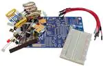
4 Kit Content
In this chapter we will take a closer look at the different components included in the LPCXpresso
Experiment Kit.
The table below contains photos and a description of all components in order to simplify identification.
Note that photos are only typical in the sense that they illustrate the components typical visual
appearance. Exact appearance can differ for the components in the kit that you have received. The
number of components shown in a picture can also differ from delivered quantity.
Most components are specified with a Digikey or Mouser equivalent. If a component gets damaged, a
new one can typically be ordered from Digikey, Mouser or any preferred component distributor. The
Digikey/Mouser number is just to get the key data of the component. The actual components in the
component kit might very well be of different brands.
Component
Description
Note
Breadboard
Digikey: 438-1109-ND
Mouser: 854-BB400T
http://en.wikipedia.org/
wiki/Breadboard
Cables, male-to-male
http://en.wikipedia.org/
wiki/Jump_wire
Connectors for
LPCXpresso board
11mm long pins
Prototype cables can be
ordered from Embedded
Artists web shop in 50 pcs
packages (EA-ACC-017).
There is another pair of
headers that looks very
similar. This pair of
connectors has longer pins.
The other pair has shorter
pins.
This pair of connectors shall
be soldered to an
LPCXpresso board to make
it experiment friendly – make
it simple to connect cables to
the pins.
There is no distributor
equivalent for this
component.
Copyright 2013 © Embedded Artists AB
�LPCXpresso Experiment Kit - User’s Guide
Page 14
Tantal capacitor
C1, C2, C12
22uF
http://en.wikipedia.org/
wiki/Tantalum_capacitor
This component is polarized.
One of the two pins is longer
than the other. This is the
positive side. There is also a
small plus sign printed on the
components on the long pin
side.
AVX: TAP226K010SCS
Digikey: 478-1874-ND
Mouser: 581TAP226K010SCS
Ceramic capacitor
C3, C4
18pF
The printed numbers on this
component is “180”.
http://en.wikipedia.org/
wiki/Ceramic_capacitor
Murata:
RPE5C2A180J2P1Z03B
Digikey: 490-3632-ND
Mouser: 81RPE5CA180J2P1Z03B
Ceramic capacitor
C5, C6, C7, C8, C9, C13
100nF
The printed numbers on this
component is “104”.
http://en.wikipedia.org/
wiki/Ceramic_capacitor
Kemet: C320C104K5R5TA
Digikey: 399-4264-ND
Mouser: 80-C320C104K5R
Ceramic capacitor
C10, C11
100nF SMT
This is a surface mounted
component and can only be
soldered to the pcb (i.e., not
used on the bread board).
http://en.wikipedia.org/
wiki/Ceramic_capacitor
Copyright 2013 © Embedded Artists AB
This is not a polarized
component.
This is not a polarized
component.
This is not a polarized
component.
Murata:
GRM21BR71E104KA01L
Digikey: 490-1673-1-ND
Mouser: 81GRM40X104K25L
�LPCXpresso Experiment Kit - User’s Guide
Page 15
Schottky diode
D1, D2
1N5817
This component is polarized.
There is a ring on one pinside of the components
(upper side in the picture).
This is the cathode of the
http://en.wikipedia.org/
diode. The other side
wiki/Semiconductor_diode (bottom side) is the anode.
http://en.wikipedia.org/
wiki/Schottky_diode
Stand-offs
H1, H2, H3, H4
Diodes Inc: 1N5817-T
Digikey: 1N5817DICT-ND
Mouser: 621-1N5817
These stand-offs are
mounted in each corner of
the pcb.
AVC: BS-13S
Any standard stand-off for
4mm holes will work.
Power jack
J1
This component and can
only be soldered to the pcb
(i.e., not used on the bread
board).
CUI Inc: PJ-102A
Digikey: CP-102A-ND
Connectors for
LPCXpresso board
J2
There is another pair of
headers that looks very
similar. This pair of
connectors has shorter pins.
The other pair has longer
pins.
This pair of connectors shall
be soldered to the pcb as a
socket to the LPCXpresso
board.
Sullins: PPTC271LFBN-RC
Digikey: S7025-ND
Debug connector
J3
This component and can
only be soldered to the pcb
(i.e., not used on the bread
board). Pin 1 is in the
top/upper left corner in the
picture.
There is no distributor
Copyright 2013 © Embedded Artists AB
�LPCXpresso Experiment Kit - User’s Guide
Page 16
equivalent for this
component.
RJ45, Ethernet connector
J4
This component and can
only be soldered to the pcb
(i.e., not used on the bread
board).
Stewart: SI-50170-F
Digikey: 380-1103-ND
Pin list, 1x3
J5, J6, J8, J12
Sullins: PEC03SAAN
Digikey: S1012E-03-ND
Pin list, 2x3
J7 and J11 combined
This component and can
only be soldered to the pcb
(i.e., not used on the bread
board).
Sullins: PEC03DAAN
Digikey: S2012E-03-ND
USB-B connector
J9
This component and can
only be soldered to the pcb
(i.e., not used on the bread
board).
TE Connectivity: 292304-2
Digikey: A98573-ND
Mouser: 571-292304-2
USB-A connector
J10
This component and can
only be soldered to the pcb
(i.e., not used on the bread
board).
TE Connectivity: 292336-1
Digikey: 292336-1-ND
Mouser: 571-292336-1
Copyright 2013 © Embedded Artists AB
�LPCXpresso Experiment Kit - User’s Guide
Page 17
socket connector for
wireless module
J15
This component and can
only be soldered to the pcb
(i.e., not used on the bread
board).
Sullins: NPPN101BFCN-RC
Digikey: S5751-10-ND
Shrouded pin list, 2x7
J16
This component and can
only be soldered to the pcb
(i.e., not used on the bread
board). Pin 1 is in the
top/upper left corner in the
picture.
Sullins: SBH11-PBPC-D07ST-BK
Digikey: S9170-ND
USB mini-B connector
J17
This component and can
only be soldered to the pcb
(i.e., not used on the bread
board).
Hirose: UX60-MB-5ST
Digikey: H2959CT-ND
Mouser: 798-UX60-MB-5ST
Pin list, 1x6
J18
Sullins: PEC06SAAN
Digikey: S1012E-06-ND
LEDs
LED1-LED8
This component is polarized.
One of the two pins is longer
than the other. This is the
positive side, the anode.
There is also a small cut on
the side of the plastic
package. This is on the short
pin side, which is the
negative side, the cathode.
http://en.wikipedia.org/
wiki/Led
Any 5mm LED with Vf around
1.7V and 150mcd at 20mA
current will work, for
example:
Digikey: 1080-1136-ND
Copyright 2013 © Embedded Artists AB
�LPCXpresso Experiment Kit - User’s Guide
Page 18
RGB-LED
LED10
http://en.wikipedia.org/
wiki/Led
This component is polarized.
There is a small cut on one
side of the plastic package.
In the component picture to
the left, the cut is on the left
side of the package.
From left to right the four
pins in the picture are:
Red-LED cathode
All LEDs anode (positive
side)
Green-LED cathode
Blue-LED cathode
Harvatek: HT-333RGBW-A
Any RGB-LED with common
anode and a low value of
blue LED Vf (around 3.2V)
will work.
7-sigment LED, dual digit
LED9
http://en.wikipedia.org/
wiki/7-segment_display
LEDs
LED11-LED18, SMT
http://en.wikipedia.org/
wiki/Led
This component is polarized.
Pin 1 is in the lower left
corner in the picture to the
left.
Lite-On Inc: LTD-4608JF
Digikey: 160-1536-5-ND
Mouser: 859-LTD-4608JF
This is a surface mounted
component and can only be
soldered to the pcb (i.e., not
used on the bread board).
This component is polarized.
There are green marks on
the cathode side.
Harvatek: HT17-2102SURC
Possible substitute is
Kingbright: APT2012SURCK
Digikey: 754-1133-1-ND
Mouser: 604APT2012SURCK
Copyright 2013 © Embedded Artists AB
�LPCXpresso Experiment Kit - User’s Guide
Page 19
PNP transistor, BC557B
Q1, Q2, Q3
http://en.wikipedia.org/
wiki/Bjt_transistor
This component is polarized.
One side of the plastic
package is flat and the other
side is rounded. When
mounting this component
make sure it is turned
correctly.
ON Semiconductor:
BC557BRL1G
Digikey:
BC557BRL1GOSCT-ND
Mouser: 863-BC557BRL1G
Resistor, 15 Kohm, 7 pcs
R1, R3, R35, R36, R41,
R42, R59
Color: Brown, Green, Black,
Red
http://en.wikipedia.org/
wiki/Resistor
Yageo: MFR-25FBF-5215K0
Digikey: 15.0KXBK-ND
Resistor, 0 ohm, 1 pcs
R2
Color: Black
http://en.wikipedia.org/
wiki/Resistor
Yageo: ZOR-25-B-52-0R
Digikey: 0.0QBK-ND
Resistor, 330 ohm, 30
pcs
R4, R5, R6, R8, R9, R10,
R11, R12, R13, R14,
R15, R16, R17, R18,
R19, R21, R22, R23,
R25, R29, R30, R31,
R32, R33, R34, R37,
R38, R62, R63, R64
Color: Orange, Orange,
Black, Black
http://en.wikipedia.org/
wiki/Resistor
Copyright 2013 © Embedded Artists AB
This is not a polarized
component.
This is not a polarized
component.
This is not a polarized
component.
Yageo: CFR-25JB-52-330R
Digikey: 330QBK-ND
�LPCXpresso Experiment Kit - User’s Guide
Page 20
Trimming potentiometer,
22 Kohm, 2 pcs
R7, R20
10Kohm equivalent from
Bourns Inc.: 3352E-1-103LF
Digikey: 3352E-103LF-ND
http://en.wikipedia.org/
wiki/Potentiometer
Photo resistor, 1 pcs
R24
http://en.wikipedia.org/
wiki/Photo_resistor
Resistor, 220 ohm, 2 pcs
R27, R28
http://en.wikipedia.org/
wiki/Resistor
Copyright 2013 © Embedded Artists AB
This is not a polarized
component.
Advanced Photonix: PDVP9002-1
Digikey: PDV-P9002-1-ND
Color: Red, Red, Black,
Black
This is not a polarized
component.
Yageo: FMP100JR-52-220R
Digikey: 220WCT-ND
Resistor, 1.5 Kohm, 8 pcs
R26, R39, R40, R60,
R61, R65, R66, R67
Color: Brown, Green, Black,
Brown
http://en.wikipedia.org/
wiki/Resistor
Yageo: FMP100JR-52-1K5
Digikey: 1.5KWCT-ND
This is not a polarized
component.
�LPCXpresso Experiment Kit - User’s Guide
Page 21
Resistor, 2 Kohm, 16 pcs
R43, R44, R45, R46,
R47, R48, R49, R50,
R51, R52, R53, R54,
R55, R56, R57, R58
This is a surface mounted
component and can only be
soldered to the pcb (i.e., not
used on the bread board).
http://en.wikipedia.org/
wiki/Resistor
Panasonic: ERJ-6ENF2001V
Digikey: P2.00KCCT-ND
Piezo buzzer, 1 pcs
SP1
This component is polarized.
One pin is longer than the
other. The longer pin is the
positive side. The top label
also indicates this side with a
small plus sign.
http://en.wikipedia.org/
wiki/Buzzer
This is not a polarized
component.
CUI Inc.: CEP-2242
Digikey: 102-1115-ND
Pushbuttons, 5 pcs
SW1-SW5
This component and can
only be soldered to the pcb
(i.e., not used on the bread
board). The reason for this is
that the pins are too short to
get reliable connection on
the bread board. There are
two other special switches in
the component kit that are
suitable for bread board
usage.
Omron: B3F-1000
Digikey: SW400-ND
Mouser: 653-B3F-1000
Pushbuttons for
breadboard, 2 pcs
These switches are for
breadboard usage. Note that
the pins must be cut to
suitable length before
mounted in the breadboard.
Panasonic: EVQ-11L05R
Digikey: P8079SCT-ND
Mouser: 667-EVQ-11L05R
Copyright 2013 © Embedded Artists AB
�LPCXpresso Experiment Kit - User’s Guide
Page 22
Rotary encoder, 1 pcs
SW6
This component and can
only be soldered to the pcb
(i.e., not used on the bread
board).
Below is without center
switch.
Panasonic: EVEGA1F1724B
Digikey: P10859-ND
Mouser: 667-EVEGA1F1724B
Voltage regulator,
MCP1700-330, 1 pcs
U1
http://en.wikipedia.org/
wiki/Lowdropout_regulator
Microcontroller,
LPC1114FN28, 1 pcs
U2
This component is polarized.
One side of the plastic
package is flat and the other
side is rounded. When
mounting this component,
make sure it is turned
correctly.
Microchip: MCP17003302E/TO
Digikey: MCP17003302E/TO-ND
Mouser: 579-MCP17003302E/TO
This component is polarized.
There is a cut in one end of
the plastic package, on the
short side. This indicates
where pin 1 is located. When
mounting this component
make sure it is turned
correctly.
NXP: LPC1114FN28/102
Digikey:
LPC1114FN28/102,12-ND
Mouser: 771LPC1114FN28/1021
Copyright 2013 © Embedded Artists AB
�LPCXpresso Experiment Kit - User’s Guide
Page 23
Headers for U2
This pair of connector headers
can (optionally) be soldered to
the pcb as a socket for U2. By
adding these
connectors/headers it is
possible to either mount the
LPCXpresso board (in J2
headers) or mount U2 in these
headers. If J2 headers are
mounted but these headers
are not, then it is not possible
to mount U2.
Sullins: PPTC141LFBN-RC
Digikey: S7012-ND
Shift register, 74HC595,
1 pcs
U3
http://en.wikipedia.org/
wiki/Shift_register
This component is polarized.
There is a cut in one end of
the plastic package, on the
short side. This indicates
where pin 1 is located – lower
left side in the picture to the
left. When mounting this
component make sure it is
turned correctly.
NXP: 74HC595N
Digikey: 568-1484-5-ND
Mouser: 771-74HC595N
Temperature sensor,
MCP9701, 1 pcs
U4
This component is polarized.
One side of the plastic
package is flat and the other
side is rounded. When
mounting this component
make sure it is turned
correctly.
Microchip: MCP9701-E/TO
Digikey: MCP9701-E/TO-ND
Mouser: 579-MCP9701-E/TO
SPI flash, 25LC080, 1
pcs
U5
http://en.wikipedia.org/
wiki/Flash_memory
This component is polarized.
There is a cut in one end of
the plastic package, on the
short side. This indicates
where pin 1 is located. When
mounting this component,
make sure it is turned
correctly.
Microchip: 25LC080D-I/P
Digikey: 25LC080D-I/P-ND
Mouser: 579-25LC080D-I/P
Copyright 2013 © Embedded Artists AB
�LPCXpresso Experiment Kit - User’s Guide
Page 24
Temperature sensor,
LM75, 1 pcs
U6
This is a surface mounted
component and can only be
soldered to the pcb (i.e., not
used on the bread board).
This component is polarized.
When rotating the components
so that the printed text on the
package can be read, pin 1 is
in the lower left side on the
package. When mounting this
component make sure it is
turned correctly.
NXP: LM75BD
Digikey: 568-4688-1-ND
Mouser: 771-LM75BD118
I2C port expander,
PCA9532, 1 pcs
U7
This is a surface mounted
component and can only be
soldered to the pcb (i.e., not
used on the bread board).
This component is polarized.
When rotating the components
so that the printed text on the
package can be read, pin 1 is
in the lower left side on the
package. When mounting this
component make sure it is
turned correctly.
NXP: PCA9532D
Digikey: 568-1039-5-ND
Mouser: 771-PCA9532D-T
12MHz HC49 crystal, 1
pcs
Y1
http://en.wikipedia.org/
wiki/Crystal_oscillator
Copyright 2013 © Embedded Artists AB
This is not a polarized
component.
CTS-Freq. Controls: ATS120B
Digikey: CTX904-ND
�LPCXpresso Experiment Kit - User’s Guide
Page 25
5 Powering Options
There are a couple of different options how to power the experiments. Below is a short list,
summarizing the options:
Controller
R2
Power option #1
Power via external +5V
supply (J1 or J17)
LPCXpresso board
Do not mount R2
Power via USB
connector on
LPCXpresso board
Yes, can also be done
LPC1114 in DIL28
Mount R2
-
Yes
mbed
Do not mount R2
Power via mbed USB
connector
Yes, can also be done
If the servo interface, USB Host interface and/or RF module are used the board MUST be powered
via an external +5V supply. Powering via the USB connectors of the LPCXpresso/mbed module is
typically not enough.
Below is a more details description. Read through all different options to determine which powering
option fits your needs.
The simplest and most common way is to let the LPCXpresso board generate the +3.3V
supply that is needed. This voltage is available on pin 29 on the LPCXpresso expansion
connector (see schematic for details). R2 should not be mounted in this case.
-
The LPCXpresso board can supply up to about 100 mA on the +3.3V supply.
Note that by turning on all LEDs and activating all features on the board it is possible
to consume more than 100 mA.
-
Note that the voltage is not exactly 3.3V, but a Schottky diode forward voltage drop
less, so around 3.15V.
In case the LPCXpresso board is not powered via its USB connector an external +5V DC
supply is needed. Connect the external supply to J1 or J17 (as described below).
-
Copyright 2013 © Embedded Artists AB
If the internal +3.3V voltage regulator on the LPCXpresso board is used, R2 shall not
be mounted. Else R2 shall be mounted (and U1 is the +3.3V regulator in use).
If current consumption on the +3.3V supply is higher that the LPCXpresso board can provide
an external +5V DC supply is needed. This is typically true when working with wireless/RF
modules and/or with the USB Host interface (J10 connector). When working with servo
motors an external +5V supply is absolutely needed.
-
An external +5V DC supply can connect to J1, which is a 2.1mm power jack with
positive center pin. Note that there is no overvoltage protection in the design. Make
sure that the connected power supply does not supply more than +5V DC. The
current capability of the external +5V DC supply should be in the region of 1-2
Ampere.
-
Connector J17 (mini-B USB connector on the back side of the pcb) can also be used
to supply an external +5V DC supply via the USB Host port on a PC/laptop/USB hub.
When using the LPC1114 in DIL28 package an external +5V DC supply is needed. Feed the
+5V via J1 or J17 (as described above) and mount R2 (in order to let U1 be the +3.3V
regulator in use).
�LPCXpresso Experiment Kit - User’s Guide
Copyright 2013 © Embedded Artists AB
Page 26
When using an mbed module, this module can generate the needed +3.3V supply (supply
comes from its own USB connector). R2 should not be mounted in this case.
-
The mbed module can supply much more current on the +3.3V supply than an
LPCXpresso board can.
-
In case the mbed module is not powered via its USB connector, it is possible to
power it with an external +5V DC supply via connector J1 or J17 (as described
above).
�LPCXpresso Experiment Kit - User’s Guide
Page 27
6 Soldering
This chapter describes how to solder the components to the naked pcb. Note that when a component
has been soldered it can no longer be used for breadboard experiment.
This chapter will not present a full beginner tutorial on soldering, but rather point out how to get started.
There are many good soldering tutorials on the Internet, which can easily be found via a Google
search. Sparkfun has a good starting guide: http://www.sparkfun.com/tutorials/354. They also have a
series of guides for soldering SMD (Surface Mounted Device) components:
http://www.sparkfun.com/tutorials/36.
The following material is requires before you start soldering:
Temperature regulated soldering iron (in the 30-80 Watt region)
Thin (0.5-0.75 mm / 20-30 mil) solder with rosin-core and non-corrosive flux
Damp sponge or brass sponge
Wire cutter
Safety glasses
It is also recommended to have a soldering fume extractor (or work in a well ventilated space and have
a fan that simply blows away the soldering fumes). In either case, be aware of the health issues with
soldering fumes.
6.1
Component Placement
The picture below illustrates the component placement on the pcb. The picture is also available as a
PDF where it is possible to search for the component designators.
Copyright 2013 © Embedded Artists AB
�LPCXpresso Experiment Kit - User’s Guide
Figure 2 – LPCXpresso Experiment Kit PCB with Component Designators
Copyright 2013 © Embedded Artists AB
Page 28
�LPCXpresso Experiment Kit - User’s Guide
Page 29
7 Experiments
This chapter contains the experiments. It is recommended to follow the order of the experiments. It has
been compiled to give you the best learning curve. There are multiple small steps in the experiments
and they build upon each other. Where appropriate, some theoretical discussions have been added.
All experiments are based around the LPCXpresso LPC111x board unless otherwise noted. Both
LPCXpresso LPC1115 and LPC1114 boards are ok to use. Some of the experiments – Ethernet and
USB - at the end of the chapter will use the LPCXpresso LPC1769 board. There is also a separate
section describing the differences between using the LPCXpresso LPC1115/LPC1114 and the
LPC1114 in DIL28 package.
It is recommended to download the LPC111x User’s Manual from NXP and have it handy. This
document is also called UM10398. Many references into this document will be done and this is also
part of the learning – how to find the relevant information in a user’s manual. It is also recommended to
have the schematic available.
It is further recommended to start working with the breadboard, as opposed to start soldering all
components to be pcb. A better time to solder the components is after having completed all the initial,
basic experiments.
7.1
Preparation
One preparation is needed before it is possible to start with the experiments. The LPCXpresso
LPC111x board must be made experiment friendly – a header with female and make connectors shall
be soldered to the LPCXpresso board. See picture below for details. Note that there are two sets (of
two) of similar 27 position headers in the component kit. It is the headers with long pins that shall be
soldered to the LPCXpresso board.
Figure 3 – LPCXpresso Board with Prototype Headers
7.2
Control a LED
In this first experiment you will learn how to control the I/O pins of the LPC111x microcontroller. More
specifically you will learn how to control a LED. This first experiment will have a very detailed
description since it is the first one and there are a lot of things to learn about how to create, compile,
download and debug a program in the LPCXpresso IDE. The level of details in the descriptions will
gradually decrease in later experiments.
Copyright 2013 © Embedded Artists AB
�LPCXpresso Experiment Kit - User’s Guide
7.2.1
Page 30
Lab 1a: Control LED
We will start with controlling LED1 in the schematic, which is found in the schematic on page 4, upper
left corner. LED1’s cathode is connected to signal GPIO_4-LED-SSEL.LED1’s anode is connected to
+3.3V via a (current limiting) series resistance. Figure 4 illustrates were LED1 can be found in the
schematic. On schematic page 2, we can see that this signal is connected to PIO0_2 on the
LPCXpresso LPC1115 board. Figure 5 illustrates where to find the signal and also where to find the
+3.3V supply.
Figure 4 – LED1 on Schematic Page 4
Figure 5 – Signal GPIO_4-LED-SSEL on Schematic Page 2
As a first step, get a LED (representing LED1), a 330 ohm resistor (representing R4), two male-to-male
prototype cables and the breadboard from the components bag. Mount these on the breadboard and
Copyright 2013 © Embedded Artists AB
�LPCXpresso Experiment Kit - User’s Guide
Page 31
connect to the LPCXpresso LPC111x board, as illustrated in Figure 6. Note that only the target
processor part of the LPCXpresso board is shown – the black box labeled LPCXpresso board. The
photo to the left illustrates which part of the real LPCXpresso his black box represents.
LPC-Link side
LPC111x target side
Figure 6 – Breadboard Connections for LED1 (breadboard view)
Figure 7 below illustrates how it can look like in reality. Note that the connections on the breadboard
are slightly different than outlined in Figure 6 above. It demonstrates that it is possible to make the
connections in many different, yet compatible, ways.
Copyright 2013 © Embedded Artists AB
�LPCXpresso Experiment Kit - User’s Guide
Page 32
Figure 7 – Breadboard Connections for LED1 (real photo)
The current through the Light Emitting Diode (LED) is limited and controlled by the series resistor. It
has to be limited since the voltage drop across the LED is fairly constant. The voltage difference
between the LED’s forward voltage drop and driving voltage must be absorbed by the series resistor.
The current through the LED (and series resistor) can be calculated as I = (Vsupply – Vleddrop) / R.
Different LEDs have different typical current levels. It can be 1, 2, 10, 20 mA for smaller LEDs. Bigger
LEDs can have much higher ratings.
The LED forward drop voltage is typically 1.5V for a red LED. Other colors have different forward
voltage drops. There are also variations between different brands. Consult the LED’s datasheet for
details about forward voltage drop and current level. The red LED’s included in the component kit has
a forward voltage drop of 1.5V and designed for 10mA current. With a 330 ohm series resistor the
current is limited to about 5mA, which is OK also. The light intensity at 5mA is acceptable for our
(experiment) purposes.
The current level determines the driving method. For moderate levels (typically below 4 mA) most
microcontrollers and logic gates can drive the LED directly. This is the method used in our
experiments. Some microcontrollers have high-current capacity outputs. The LPC1110 family
microcontrollers have a 20 mA output pin (PIO0_7, see datasheet for details).
Almost all output pins have higher current capabilities sinking current than driving current. It is
therefore common to connect LEDs like in Figure 4, with the cathode connected to the microcontroller
pin. When driving, current is flowing into the micro controller pin (i.e., sinking current).
Another reason for letting the microcontroller drive the LED by sinking current is that most
microcontrollers power-up with all pins as inputs with pull-up resistors enabled. This basically means
that the pin will be driven high weakly. The LED will not turn on shortly during a power-up. It will be at a
known (off) state until the application program controls the LED actively.
If the driving current is higher (> 5 mA) a high-current driver chip can be used, or discrete
transistors/mosfets.
A LED is a polarized component, meaning that it matters how the two ends are connected. The two
ends are called anode and cathode, respectively. Current flows from anode to cathode, but blocks in
the reverse direction. Sometimes the anode is called the positive side and cathode the negative side.
The cathode is typically marked somehow on a LED (shorter pin, cut in plastic package, etc).
Mounting a LED the wrong way has no catastrophic result. The result is that the LED will not light
(since current through the LED will be blocked). Failing to add the series resistor will have more sever
effects, though. Depending on high strong (how much current it can deliver) the power supply is, the
current level through the LED can become high enough to destroy the LED. Therefore, be careful to
always connect a series resistor with correct resistance value.
The LPC111x is a relatively low pin count processor with only 48 pins. This is true for the package
used on the LPCXpresso board. There are other packages with different number of pins for this
processor also. The external pins on the chip package are not enough for connecting all internal
peripheral units to unique pins. Instead each I/O pin has up to four alternative connections. Read the
LPC111x user’s manual for more information. You will have to read a lot in this document so you better
get started immediately. Have a look in chapter 7 - LPC1100/LPC1100C/LPC1100L series: I/O
configuration in the LPC111x user’s manual for a description of the how the alternative pin functions
can be controlled.
Pin PIO0_2 is controlled by register IOCON_PIO0_2. In the description for this register we can see that
there are three alternative pin functions:
-
Copyright 2013 © Embedded Artists AB
PIO0_2, a general purpose input/output, port #0, pin #2
�LPCXpresso Experiment Kit - User’s Guide
-
SSEL0, a control signal for peripheral block SSP
-
CT16B0_CAP0, an input signal to 16-bit timer #0
Page 33
Note that only one functional signal can be connected to the pin at any given point in time. It is
however possible to change during program execution. By default, after reset, the register is initialized
to PIO0_2, have a pull-up resistor enabled, input hysteresis disabled and to be a standard push/pull
GPIO output (if defined as an output). Another register controls the direction of the general purpose
digital input/output and this register initialize PIO0_2 to be an input after reset.
Hence, after a reset, PIO0_2 is an input with pull-up resistor enabled. The pin is pulled high weakly but
cannot source any larger current. That means that LED1 will be off after reset (because the LED will
turn on when PIO0_2 is pulled low and if enough current can sink into the pin).
All LPC111x registers are defined in file: LPC11xx.h. It is part of the framework needed to program
the LPC111x. Have a look in file LPC11xx.h. It is found in the CMSIS library, in the inc subdirectory.
What address is register IOCON_PIO0_2 defined as? _________________________________
(you will have to derive the address in several steps – tip: start searching for the LPC_IOCON register
at the end of the LPC11xx.h file. The register will be accessed as: LPC_IOCON->PIO0_2)
Is the derived address the same as in the LPC111x user’s manual? ____________
Now, have a look in chapter 12: LPC111x/LPC11Cxx General Purpose I/O (GPIO) in the LPC111x
user’s manual for a description of how the general purpose I/O functionality is controlled. There is a
GPIO data direction register that controls the direction of each pin in a port. PIO0_2 belongs to port #0.
Bit #2 in register GPIO0DIR controls the direction of the pin. See Figure 8 for details.
Figure 8 – GPIO Data Direction Register
Register GPIO0DATA holds the current state of the pins in port #0. Bit 2 in this register reflects the
state of pin PIO0_2. This is regardless if the pin is an input or output. If a pin is an output the value in
GPIOxDATA is driven to the pin.
Figure 9 – GPIO Data Register
There are also several registers related to interrupt functionality. We will not work with that right now. In
later experiments we will return to this.
Copyright 2013 © Embedded Artists AB
�LPCXpresso Experiment Kit - User’s Guide
Page 34
Note that registers GPIO0DIR and GPIO0DATA are accessed as LPC_GPIO0->DIR and
LPC_GPIO0->DATA, respectively.
Below is the two statements needed to first set PIO0_2 to an output and then pull the output low. This
will turn the LED on.
// Set PIO0_2 as an output
LPC_GPIO0->DIR = LPC_GPIO0->DIR | (0x1DATA & ~(0x1> 8) & 0xff;
buf[2] = address & 0xff;
SSP0Send(&buf[0], 3);
//read bytes from E2PROM
SSP0Receive(pBuf, length);
//pull SSEL/CS high
GPIOSetValue(SSEL_GPIO_8_PORT, SSEL_GPIO_8_PIN, SSEL_HIGH);
}
/*****************************************************************************
** Function name:
spiE2PROMwrite
** Descriptions:
This function will write bytes to the SPI E2PROM
** parameters:
address in memory region, buffer pointer and block length
** Returned value:
None
**
*****************************************************************************/
void spiE2PROMwrite( uint16_t address, uint8_t *pBuf, uint32_t length )
{
uint8_t buf[3];
//Insert code here to break up large write operation into several
//page write operations...
//Do not forget to add a 5ms delay after each page write operation!
//pull SSEL/CS low
GPIOSetValue(SSEL_GPIO_8_PORT, SSEL_GPIO_8_PIN, SSEL_LOW);
//output write command and address
buf[0] = INST_WRITE;
buf[1] = (address >> 8) & 0xff;
buf[2] = address & 0xff;
SSP0Send(&buf[0], 3);
//send bytes to write E2PROM
SSP0Send(pBuf, length);
//pull SSEL/CS high
GPIOSetValue(SSEL_GPIO_8_PORT, SSEL_GPIO_8_PIN, SSEL_HIGH);
}
Add functionality in the write operation to check so that no page boundaries are crossed. Even better,
add functionality to break up a large write block to smaller, correctly addressed page writes. Do not
forget to add functionality in the write function to set the write enable latch before every write operation.
Copyright 2013 © Embedded Artists AB
�LPCXpresso Experiment Kit - User’s Guide
Page 86
Create a program that writes a string and reads it back to verify that the write operation was
successful. Also let the program print the content of the memory locations directly after power-up. By
doing so it is also possible to verify that the SPI E2PROM is a non-volatile memory that keeps the
content over a power cycle. Build the breadboard setup below and verify that it is possible to write and
read in the memory region on the 25LC080 chip. Note that the 330 ohm series resistor on the MISO
pin (pin 2 of the 25LC080) is not strictly needed. It is a safety precaution in case a faulty or wrong
program executes on the LPC111x, making the MISO pin an output in the LPC111x. If this happens
then the signal will have two drivers. This can cause damage to the respective pin drivers on the chips.
Figure 54 – Breadboard with SPI E2PROM
Copyright 2013 © Embedded Artists AB
�LPCXpresso Experiment Kit - User’s Guide
Page 87
7.13 Work with Interrupts
In this experiment you will learn how to incorporate interrupts in your program. Interrupts are a
powerful concept in embedded programming. It is a way to interrupt the normal program execution flow
to service something else quickly. This “something else” is typically a peripheral block that needs to be
serviced or it is an external event that needs attention/a reaction.
There is a functional block in the LPC111x that is called the Nested Vectored Interrupt Controller
(NVIC). It is an integral part of the Cortex-M0 core. The NVIC can be regarded as a peripheral block,
but a special one. It is programmed/setup via registers, just like any other peripheral. It supports 32
interrupt sources and there are four programmable priority levels. Individual interrupts can be masked
(i.e., disabled) in the NVIC. It is also possible to generate an interrupt via software - writing in a special
register will trigger the specified interrupt.
An indication that the NVIC is a special function block is that all information can be found in chapter
28.6.2 – Nested Vectored Interrupt Controller in the LPC111x user’s manual. This is the chapter that
contains Cortex-M0 core information. Chapter 6 - LPC111x/LPC11Cxx Nested Vectored Interrupt
Controller (NVIC) basically only contains a table (Table 54) that lists the different interrupt sources in
the LPC111x. Almost all of the 32 sources are used.
Have a look in file LPC11xx.h. It is found in the CMSIS library, in the inc sub-directory. Amongst
other things, the typedef declaration below is found in this file. It lists the names and numbers of
the different interrupt sources.
...
/* Interrupt Number Definition */
typedef enum IRQn
{
/****** Cortex-M0 Processor Exceptions Numbers ***********************************/
NonMaskableInt_IRQn
= -14,
/* 2 Non Maskable Interrupt
*/
HardFault_IRQn
= -13,
/* 3 Cortex-M0 Hard Fault Interrupt
*/
SVCall_IRQn
= -5,
/* 11 Cortex-M0 SV Call Interrupt
*/
PendSV_IRQn
= -2,
/* 14 Cortex-M0 Pend SV Interrupt
*/
SysTick_IRQn
= -1,
/* 15 Cortex-M0 System Tick Interrupt
*/
/****** LPC11xx Specific Interrupt Numbers ***************************************/
WAKEUP0_IRQn
= 0,
/* All I/O pins can be used as wakeup source. */
WAKEUP1_IRQn
= 1,
/* There are 13 pins in total for LPC11xx
*/
WAKEUP2_IRQn
= 2,
WAKEUP3_IRQn
= 3,
WAKEUP4_IRQn
= 4,
WAKEUP5_IRQn
= 5,
WAKEUP6_IRQn
= 6,
WAKEUP7_IRQn
= 7,
WAKEUP8_IRQn
= 8,
WAKEUP9_IRQn
= 9,
WAKEUP10_IRQn
= 10,
WAKEUP11_IRQn
= 11,
WAKEUP12_IRQn
= 12,
SSP1_IRQn
= 14,
/* SSP1 Interrupt
*/
I2C_IRQn
= 15,
/* I2C Interrupt
*/
TIMER_16_0_IRQn
= 16,
/* 16-bit Timer0 Interrupt
*/
TIMER_16_1_IRQn
= 17,
/* 16-bit Timer1 Interrupt
*/
TIMER_32_0_IRQn
= 18,
/* 32-bit Timer0 Interrupt
*/
TIMER_32_1_IRQn
= 19,
/* 32-bit Timer1 Interrupt
*/
SSP0_IRQn
= 20,
/* SSP0 Interrupt
*/
UART_IRQn
= 21,
/* UART Interrupt
*/
ADC_IRQn
= 24,
/* A/D Converter Interrupt
*/
WDT_IRQn
= 25,
/* Watchdog timer Interrupt
*/
BOD_IRQn
= 26,
/* Brown Out Detect(BOD) Interrupt
*/
EINT3_IRQn
= 28,
/* External Interrupt 3 Interrupt
*/
EINT2_IRQn
= 29,
/* External Interrupt 2 Interrupt
*/
EINT1_IRQn
= 30,
/* External Interrupt 1 Interrupt
*/
EINT0_IRQn
= 31,
/* External Interrupt 0 Interrupt
*/
} IRQn_Type;
...
Copyright 2013 © Embedded Artists AB
�LPCXpresso Experiment Kit - User’s Guide
Page 88
An interrupts source is enabled by the call below. The example enables the 16-bit timer #0 interrupt.
/* enable 16-bit timer #0 interrupt */
NVIC_EnableIRQ(TIMER_16_0_IRQn);
It is also possible to disable an interrupt source.
/* disable 16-bit timer #0 interrupt */
NVIC_DisableIRQ(TIMER_16_0_IRQn);
Normally it is good system design practice to keep the execution time in the interrupts as short as
possible. The actions that are needed immediately are done in the interrupt service routine (ISR).
Actions that can wait should be scheduled for later execution in the normal program flow. If it is not
possible to keep execution time in an ISR short, nested interrupts can be used. Nested interrupts
means that an interrupt can interrupt another interrupt if it has higher priority. Four priority levels (0-3)
are supported in the NVIC hardware. The lower the number is, the higher the priority is. Interrupts with
the same priority cannot interrupt each other. It is possible to set the priority of an interrupt like this:
/* set priority of specified interrupt
IRQn_Type
, priority (0..3) */
void NVIC_SetPriority(TIMER_16_0_IRQn, (prioSYSAHBCLKCTRL |= (1LCR = 0x83;
/* 8 bits, no Parity, 1 Stop bit */
regVal = LPC_SYSCON->UARTCLKDIV;
Fdiv = (((SystemCoreClock/LPC_SYSCON->SYSAHBCLKDIV)/regVal)/16)/baudrate;
LPC_UART->DLM
LPC_UART->DLL
LPC_UART->LCR
LPC_UART->FCR
=
=
=
=
Fdiv / 256;
Fdiv % 256;
0x03;
0x07;
/* DLAB = 0 */
/* Enable and reset TX and RX FIFO. */
/* Read to clear the line status. */
regVal = LPC_UART->LSR;
/* Ensure a clean start, no data in either TX or RX FIFO. */
while ( (LPC_UART->LSR & (LSR_THRE|LSR_TEMT)) != (LSR_THRE|LSR_TEMT) );
while ( LPC_UART->LSR & LSR_RDR )
{
regVal = LPC_UART->RBR;
/* Dump data from RX FIFO */
}
return;
}
/*****************************************************************************
Copyright 2013 © Embedded Artists AB
�LPCXpresso Experiment Kit - User’s Guide
Page 105
** Function name: UARTSendChar
**
** Descriptions:
Send a byte/char of data to the UART 0 port
**
** parameters:
byte to send
** Returned value: None
**
*****************************************************************************/
void UARTSendChar(uint8_t toSend)
{
/* THRE status, contain valid data */
while ( !(LPC_UART->LSR & LSR_THRE) )
;
LPC_UART->THR = toSend;
}
/*****************************************************************************
** Function name: UARTReceive
**
** Descriptions:
Receive a block of data from the UART 0 port based
**
on the data length
**
** parameters:
buffer pointer, data length
** Returned value: Number of received bytes
**
*****************************************************************************/
uint32_t UARTReceive(uint8_t *buffer, uint32_t length, uint32_t blocking)
{
uint32_t recvd = 0;
uint32_t toRecv = length;
if (blocking) {
while (toRecv) {
/* wait for data */
while (!(LPC_UART->LSR & LSR_RDR));
*buffer++ = LPC_UART->RBR;
recvd++;
toRecv--;
}
}
else {
while (toRecv) {
/* break if no data */
if (!(LPC_UART->LSR & LSR_RDR)) {
break;
}
*buffer++ = LPC_UART->RBR;
recvd++;
toRecv--;
}
}
return recvd;
}
Function UARTSendChar() transmits one byte/char of data. UARTReceive() is a function
that can receive data either blocking or non-blocking. Blocking means that the processor spends all
time idle waiting (in the function call) for the wanted number of characters to be received. Non-blocking
means that the function returns with the number of available characters that was/were received. It will
be somewhere between zero (0) and length number of characters. Another name for non-blocking
is asynchronous function call. Blocking calls can also be called synchronous function calls.
Place the UART related code in file uart.c, and place the function prototype declarations in file
uart.h.
Copyright 2013 © Embedded Artists AB
�LPCXpresso Experiment Kit - User’s Guide
7.15.1
Page 106
Lab 14a: Transmitting and Receiving via the UART
Expand the UARTSendChar() function to UARTSendString(uint8_t *pStr)
function (transmits a zero-terminated string – the terminating zero is not transmitted) and
UARTSendBuffer(uint8_t *pBuf, uint16_t length) functions.
Create a small program that makes use of these transmission functions. Also let the program echo
every received character.
Connect the FTDI cable and verify that the program works as intended.
Test to echo a longer string: “Received: x” (where x is the received char) from the LPC111x.
Type characters on the PC terminal program and observe the echoed response from the LPC111x.
Now test to send a series of 100 characters back to back from the PC. This is for example done by
sending a 100 byte long file. Select Send file in the File menu. What will happen?
_____________________________________________________________________________
_____________________________________________________________________________
Every received character results in several characters echoed back to the PC. These echoed
characters will take longer time than the time of the (originally) received character. Characters are
received at full speed (back-to-back) and soon both transmit and received FIFOs will be full. Received
characters will start to be missed.
The solution is flow control. A receiver must be able to inform a transmitter that it must wait for a while
before transmitting more characters. One commonly used software solution for this is called Xon/Xoff
flow control, see: http://en.wikipedia.org/wiki/Software_flow_control for more information. A commonly
used hardware solution is called RTS/CTS flow control, see:
http://en.wikipedia.org/wiki/Flow_control_%28data%29#Hardware_flow_control
7.15.2
Lab 14b: Direct printf() to UART
In exercise Lab 4a-4d, semihosting was explored. In this experiment the printf() output will be sent to
the UART communication channel. Remember that the C runtime library had to be of the correct type
for semihosting to work. Have a look at Figure 21 and make sure the project settings select Redlib
(nohost) as the C runtime library for this exercise. There are hooks in Redlib for directing the printf()output to any wanted communication channel – the UART in this case.
The two simple functions below is all that is needed to direct the printf()-output to the UART and also to
let scanf()-input come from the UART.
#include "stdio.h"
#include "uart.h"
...
//use UART for printf
int __sys_write(int iFileHandle, char *pcBuffer, int iLength)
{
UARTSendBuffer((uint8_t *)pcBuffer,iLength);
//send data buffer to UART
return iLength;
}
int __sys_readc(void)
{
char c;
UARTReceive((uint8_t*)&c, 1, TRUE);
return (int)c;
}
Place the two functions above in a file called retarget.c.
Copyright 2013 © Embedded Artists AB
�LPCXpresso Experiment Kit - User’s Guide
Page 107
Create a program that outputs a message, with the help of printf(), on the UART channel and
receive the message on a terminal program on a PC. Also let the program verify that scanf()
works.
Remember that the UART must still be initialized before printf()/scanf() are used.
7.15.3
Lab 14c: Interrupt driven UART handling and ring buffers
Blocking function calls can be problematic since it can block other activities in a system. A way to
handle this is to create circular buffers, both for received characters and transmission. An interrupt
handler place received characters in the receive buffer. The program can then peek into the circular
buffer to check if there are any received characters. If not, execution can continue with other tasks.
Below is code the implements UART receive functionality with the help of interrupts and circular
buffers. The interrupt routine (ISR) handle both receive and transmit interrupts. Study the code to
understand how it works.
#include "lpc11xx.h"
#include "uart.h"
//size of transmit buffer - size MUST be power of two
#define TX_BUFFER_SIZE 256
#define TX_BUFFER_MASK (TX_BUFFER_SIZE-1)
//size of receive buffer - size MUST be power of two
#define RX_BUFFER_SIZE 256
#define RX_BUFFER_MASK (RX_BUFFER_SIZE-1)
#define
#define
#define
#define
#define
#define
#define
#define
LSR_RDR
LSR_OE
LSR_PE
LSR_FE
LSR_BI
LSR_THRE
LSR_TEMT
LSR_RXFE
0x01
0x02
0x04
0x08
0x10
0x20
0x40
0x80
#define IER_RBR
#define IER_THRE
#define IER_RLS
0x01
0x02
0x04
#define
#define
#define
#define
#define
0x01
0x03
0x02
0x06
0x01
static
static
static
static
IIR_PEND
IIR_RLS
IIR_RDA
IIR_CTI
IIR_THRE
volatile
volatile
volatile
volatile
uint8_t
uint32_t
uint32_t
uint8_t
txBuf[TX_BUFFER_SIZE];
txHead = 0;
txTail = 0;
txRunning = FALSE;
static volatile uint8_t rxBuf[RX_BUFFER_SIZE];
static volatile uint32_t rxHead = 0;
static volatile uint32_t rxTail = 0;
/*****************************************************************************
** Function name: UARTInit
**
** Descriptions:
Initialize UART0 port, setup pin select,
**
clock, parity, stop bits, FIFO, etc.
**
** parameters:
UART baudrate
** Returned value: None
**
*****************************************************************************/
void UARTInit(uint32_t baudrate)
Copyright 2013 © Embedded Artists AB
�LPCXpresso Experiment Kit - User’s Guide
Page 108
{
uint32_t Fdiv;
uint32_t regVal;
NVIC_DisableIRQ(UART_IRQn);
LPC_IOCON->PIO1_6
LPC_IOCON->PIO1_6
LPC_IOCON->PIO1_7
LPC_IOCON->PIO1_7
&=
|=
&=
|=
~0x07;
0x01;
~0x07;
0x01;
/* UART I/O config */
/* UART RXD */
/* UART TXD */
/* Enable UART clock */
LPC_SYSCON->SYSAHBCLKCTRL |= (1LCR = 0x83;
/* 8 bits, no Parity, 1 Stop bit */
regVal = LPC_SYSCON->UARTCLKDIV;
Fdiv = (((SystemCoreClock/LPC_SYSCON->SYSAHBCLKDIV)/regVal)/16)/baudrate;
LPC_UART->DLM
LPC_UART->DLL
LPC_UART->LCR
LPC_UART->FCR
=
=
=
=
Fdiv / 256;
Fdiv % 256;
0x03;
/* DLAB = 0 */
0x07;
/* Enable and reset TX and RX FIFO. */
/* Read to clear the line status. */
regVal = LPC_UART->LSR;
/* Ensure a clean start, no data in either TX or RX FIFO. */
while ( (LPC_UART->LSR & (LSR_THRE|LSR_TEMT)) != (LSR_THRE|LSR_TEMT) );
while ( LPC_UART->LSR & LSR_RDR )
{
regVal = LPC_UART->RBR; /* Dump data from RX FIFO */
}
//initialize the transmit data queue
txHead
= 0;
txTail
= 0;
txRunning = FALSE;
//initialize the receive data queue
rxHead
= 0;
rxTail
= 0;
/* Enable the UART Interrupt */
NVIC_EnableIRQ(UART_IRQn);
LPC_UART->IER = IER_RBR | IER_THRE | IER_RLS; /* Enable UART interrupt */
}
/*****************************************************************************
** Function name:
UART_IRQHandler
**
** Descriptions:
UART interrupt handler
**
** parameters:
None
** Returned value:
None
**
*****************************************************************************/
void UART_IRQHandler(void)
{
volatile uint8_t IIRValue, LSRValue, statusReg;
uint8_t Dummy = Dummy;
volatile uint32_t tmpHead;
volatile uint32_t tmpTail;
statusReg = IIRValue = LPC_UART->IIR;
IIRValue >>= 1;
/* skip pending bit in IIR */
IIRValue &= 0x07;
/* check bit 1~3, interrupt identification */
if (IIRValue == IIR_RLS)
/* Receive Line Status */
{
LSRValue = LPC_UART->LSR;
/* Receive Line Status */
if (LSRValue & (LSR_OE | LSR_PE | LSR_FE | LSR_RXFE | LSR_BI))
{
/* There are errors or break interrupt */
Copyright 2013 © Embedded Artists AB
�LPCXpresso Experiment Kit - User’s Guide
Page 109
/* Read LSR will clear the interrupt */
Dummy = LPC_UART->RBR; //Dummy read on RX to clear interrupt, then bail out
return;
}
if (LSRValue & LSR_RDR) /* Receive Data Ready */
{
/* If no error on RLS, normal ready, save into the data buffer. */
/* Note: read RBR will clear the interrupt */
tmpHead = (rxHead + 1) & RX_BUFFER_MASK;
rxHead = tmpHead;
if(tmpHead == rxTail)
tmpHead = LPC_UART->RBR;
else
rxBuf[tmpHead] = LPC_UART->RBR;
//dummy read to reset IRQ flag
//will reset IRQ flag
}
}
else if (IIRValue == IIR_RDA) /* Receive Data Available */
{
/* Receive Data Available */
tmpHead = (rxHead + 1) & RX_BUFFER_MASK;
rxHead = tmpHead;
if(tmpHead == rxTail)
tmpHead = LPC_UART->RBR;
else
rxBuf[tmpHead] = LPC_UART->RBR;
//dummy read to reset IRQ flag
//will reset IRQ flag
}
else if (IIRValue == IIR_CTI) /* Character timeout indicator */
{
/* Character Time-out indicator */
; //functionality not implemented
}
else if (IIRValue == IIR_THRE) /* THRE, transmit holding register empty */
{
//check if all data is transmitted
if (txHead != txTail)
{
uint32_t bytesToSend;
if (statusReg & 0xc0)
bytesToSend = 16;
else
bytesToSend = 1;
//FIFO enabled
//no FIFO enabled
do
{
//calculate buffer index
tmpTail = (txTail + 1) & TX_BUFFER_MASK;
txTail = tmpTail;
LPC_UART->THR = txBuf[tmpTail];
} while((txHead != txTail) && --bytesToSend);
}
//all data has been transmitted
else
{
txRunning = FALSE;
LPC_UART->IER &= ~IER_THRE;
}
//disable TX IRQ
}
}
/*****************************************************************************
** Function name: UARTSendChar
**
** Descriptions:
Send a byte/char of data to the UART 0 port
**
** parameters:
byte to send
** Returned value: None
**
*****************************************************************************/
void UARTSendChar(uint8_t toSend)
{
Copyright 2013 © Embedded Artists AB
�LPCXpresso Experiment Kit - User’s Guide
Page 110
uint32_t tmpHead;
//calculate head index
tmpHead = (txHead + 1) & TX_BUFFER_MASK;
//wait for free space in buffer
while(tmpHead == txTail)
;
//disable TX IRQ
LPC_UART->IER &= ~IER_THRE;
if(txRunning == TRUE)
{
txBuf[tmpHead] = toSend;
txHead
= tmpHead;
}
else
{
txRunning = TRUE;
/* Extra check - should not be needed: THRE status, contain valid data */
while ( !(LPC_UART->LSR & LSR_THRE) )
;
LPC_UART->THR = toSend;
}
//enable TX IRQ
LPC_UART->IER |= IER_THRE;
}
/*****************************************************************************
** Function name: UARTGetCharBlock
**
** Descriptions:
Receive a char from UART 0
**
** parameters:
None
** Returned value: Received char
**
*****************************************************************************/
uint8_t UARTGetCharBlock(void)
{
//exercise to implement this function...
}
/*****************************************************************************
** Function name: UARTGetChar
**
** Descriptions:
Receive a char from UART 0
**
** parameters:
pointer to where to store received char
** Returned value: TRUE if char received, else FALSE
**
*****************************************************************************/
uint8_t UARTGetChar(uint8_t *pRxChar)
{
uint32_t tmpTail;
/* check if buffer is empty */
if(rxHead == rxTail)
return FALSE;
tmpTail = (rxTail + 1) & RX_BUFFER_MASK;
rxTail = tmpTail;
*pRxChar = rxBuf[tmpTail];
return TRUE;
}
Copyright 2013 © Embedded Artists AB
�LPCXpresso Experiment Kit - User’s Guide
Page 111
Place the UART related code in file uart.c, and place the function prototype declarations in file
uart.h. Do not forget to remove the retarget.c file and change back C runtime library to
Redlib (semihost).
The code is quite complex and builds on two circular buffers. The receive and transmit buffers can
have different sizes, but they must be a power of two. The reason for this is the special mask
operations (bitwise-AND with size minus 1). Characters to be transmitted should be placed in a circular
buffer. If transmission is not active, start transmission again with the first character in the buffer. As
soon as a character has been transmitted the interrupt handler checks if there are more characters to
be transmitted in the buffer. If no more, disable the transmission interrupt.
Extend the code above to also implement a uint8_t UARTGetCharBlock(void) function
that blocks until a char has been received and returns the received character. Let the new function
make use of the UARTGetChar() function.
Also update the UARTSendString() and UARTSendBuffer() functions from Lab14a. The
suggested function prototypes are as below. These functions are needed on future experiments (with
RF modules).
/*****************************************************************************
** Function name: UARTSendString
**
** Descriptions:
Send a null-terminated string to UART 0 port
**
** parameters:
byte to send and if call should wait for transfer to complete
** Returned value: None
**
*****************************************************************************/
void UARTSendString(uint8_t *pStr, uint8_t blocking);
/*****************************************************************************
** Function name: UARTSendBuffer
**
** Descriptions:
Send a number of bytes/chars of data to UART 0 port
**
** parameters:
data to send, number of bytes and if call is blocking
** Returned value: None
**
*****************************************************************************/
void UARTSendBuffer(uint8_t *pBuf, uint16_t length, uint8_t blocking);
Create an application that demonstrates receive and transmit circular buffers. The receive overflow
problem in the previous experiment can for example be handled to some extent if the buffers are large
enough.
Copyright 2013 © Embedded Artists AB
�LPCXpresso Experiment Kit - User’s Guide
Page 112
7.16 Extra: Work with RF-module
In this experiment you will learn how to work with radio modules.
Note that the breadboard cannot be used in these experiments. The RF module connectors
have 2.0 mm pitch as opposed to the 2.54 mm pitch found on breadboards. Also note that the
radio modules used in these experiments are not included and must be purchased separately.
The RF module interface is found on schematic page 7, also replicated in the picture below. All
components in Figure 63 must be soldered. J2, the LPCXpresso board connector on schematic page
2, must also be soldered.
Figure 63 – RF Module Interface on Schematic Page 7
Many RF modules come in the XBee® physical form factor. An UART interface is connected for
communication with the RF module. All 20 pins are however available via connectors J13/J14 in case
some other pins must be connected for more advanced experiments where more functionality in the
modules is utilized. Figure 64 illustrates how an XBee module is mounted in J15. Note that J12 should
normally have a shorting jumper in position 1-2, the right position as illustrated in the picture below.
Figure 64 – XBee® Module Mounted in J15
Copyright 2013 © Embedded Artists AB
�LPCXpresso Experiment Kit - User’s Guide
Page 113
A shorting jumper in position 1-2 of J12 means that the RF module is powered from the 3.3V supply
from the LPCXpresso or mbed board. This supply is somewhat current limited (about 100-150mA) but
will be sufficient for most RF modules. However, some modules have higher current requirements and
then the shorting jumper should be placed in 2-3 position of J12. This is the left position for the jumper,
when viewed like in Figure 64. In this case, an external power supply can power the RF module (via
U1 voltage regulator).
The RF-module experiments are based on the interrupt-driven UART code from Lab14c. The
UARTSendString() and UARTSendBuffer()functions are needed.
7.16.1
Lab 15a: XBee™ RF-Module
This exercise requires at least two XBee modules and the same number of experiment boards to be
able to test XBee communication. One of the boards will be setup as a controller and the other as
node(s).
There are many different XBee modules with different functionality and programming interfaces. The
XBee module used in this experiment is: XB24-AWI-001. It can be bought from for example Digikey:
XB24-AWI-001-ND or Mouser: 888-XB24-AWI-001.
Prepare the boards by plugging in the XBee module in the J15 socket and inserting a jumper in J12 at
position 1-2 to get power from the LPCXpresso board.
The XBee driver is quite large and is found in the xbee.c and xbee.h files in the code framework
that is provided. Copy all drivers created so far into the project, including the interrupt driven UART
code from Lab 14c.
Below is the template for the main() program.
#include
#include
#include
#include
#include
#include
#include
"stdio.h"
"LPC11xx.h"
"type.h"
"board.h"
"gpio.h"
"delay.h"
"xbee.h"
/*
* Application configuration
*
* CFG_ACT_AS_COORDINATOR - (1) - Configure the XBee module to act as a coordinator.
*
(0) - Configure the XBee module to act as an end-device
*/
#define CFG_ACT_AS_COORDINATOR (0)
/*
* RF message IDs, add your own here but make sure that the coordinator
* and the nodes have the same numbering.
*/
#define RFPT_SET_LED (1)
// Forward declarations
static void xbeeUp(uint8_t up);
static void xbeeNode(uint32_t addrHi, uint32_t addrLo, uint8_t rssi);
static void xbeeTxStatus(uint8_t frameId, xbeeTxStatus_t error);
static void xbeeData(uint32_t addrHi, uint32_t addrLo, uint8_t rssi,
uint8_t* buf, uint8_t len);
static xbee_callb_t callbacks = {
xbeeUp,
xbeeNode,
xbeeTxStatus,
xbeeData
};
static uint8_t devIsReady = 0;
Copyright 2013 © Embedded Artists AB
�LPCXpresso Experiment Kit - User’s Guide
Page 114
volatile uint32_t ms_ticks = 0;
/*****************************************************************************
** Function name: SysTick_Handler
**
** Descriptions:
Interrupt handler. Updates the ms_ticks variable to hold
**
the number of milliseconds since start. This will be
**
reasonably accurate and is used by the Xbee driver to
**
handle timeouts.
**
** parameters:
None
** Returned value: The time in milliseconds
**
*****************************************************************************/
void SysTick_Handler(void) {
ms_ticks += 10;
}
/*****************************************************************************
** Function name: xbeeUp
**
** Descriptions:
XBee node up/down callback.
**
** parameters:
up will be 1 if the node is up, 0 if it is down
** Returned value: None
**
*****************************************************************************/
static void xbeeUp(uint8_t up)
{
printf("RF: Xbee Up (%d)\r\n", up);
devIsReady = up;
}
/*****************************************************************************
** Function name: xbeeNode
**
** Descriptions:
XBee node discover callback. Will be called as a response
**
to a Xbee node discovery request. All found nodes are
**
reported back one-by-one through this callback.
**
** parameters:
addrHi - upper 32 bits of the 64-bit node address,
**
addrLo - lower 32 bits of the 64-bit node address,
**
rssi
- signal strength
** Returned value: None
**
*****************************************************************************/
static void xbeeNode(uint32_t addrHi, uint32_t addrLo, uint8_t rssi)
{
printf("RF: Node %x:%x rssi=%d\r\n", addrHi, addrLo, rssi);
}
/*****************************************************************************
** Function name: xbeeTxStatus
**
** Descriptions:
Transmit status callback. Called as a result of a packet
**
being sent from the Xbee node.
**
** parameters:
frameId - ID of the frame that was sent,
**
status - status of the transmit request
** Returned value: None
**
*****************************************************************************/
static void xbeeTxStatus(uint8_t frameId, xbeeTxStatus_t status)
{
if (status != XBEE_TX_STAT_OK) {
printf("RF: [%d] TX failed %d\r\n", frameId, status);
}
}
/*****************************************************************************
Copyright 2013 © Embedded Artists AB
�LPCXpresso Experiment Kit - User’s Guide
Page 115
** Function name: xbeeTxStatus
**
** Descriptions:
Received data callback. Called when data has been received
**
by the Xbee node.
**
** parameters:
addrHi - upper 32 bits of the 64-bit node address,
**
addrLo - lower 32 bits of the 64-bit node address,
**
rssi
- signal strength,
**
buf
- buffer containing the data,
**
len
- number of received bytes,
** Returned value: None
**
*****************************************************************************/
static void xbeeData(uint32_t addrHi, uint32_t addrLo, uint8_t rssi,
uint8_t* buf, uint8_t len)
{
int i = 0;
printf("xbeeData %x:%x, rssi=%d, len=%d\r\n", addrHi, addrLo, rssi, len);
if (len < 1) {
return;
}
switch (buf[0]) {
// Set LED request. This is a two byte request where the data
// indicates if the LED should be turned on or off.
case RFPT_SET_LED:
if (len > 1) {
if (buf[1] == 1) {
GPIOSetValue(LED1_PORT, LED1_PIN, LED_ON);
} else {
GPIOSetValue(LED1_PORT, LED1_PIN, LED_OFF);
}
}
break;
default:
for (i = 0; i < len; i++) {
if (i > 0 && (i%8) == 0) {
printf("\r\n");
}
printf("%x ", buf[i]);
}
printf("\r\n");
break;
}
}
/*****************************************************************************
** Function name: sendSetLedRequest
**
** Descriptions:
Broadcasts a request over Xbee to set the status of the LED
**
** parameters:
ledOn - should the LED be lit or not
** Returned value: ERR_OK or an error code
**
*****************************************************************************/
static error_t sendSetLedRequest(uint8_t ledOn)
{
uint8_t data[2];
uint8_t id = 0;
data[0] = RFPT_SET_LED;
data[1] = ledOn;
return xbee_send(XBEE_ADDRHI_BROADCAST, XBEE_ADDRLO_BROADCAST, data, 2, &id);
}
int main (void)
{
error_t err;
uint8_t state = 0;
uint8_t oldState = !SW_PRESSED;
Copyright 2013 © Embedded Artists AB
�LPCXpresso Experiment Kit - User’s Guide
Page 116
//Set LED1 pin as output
...
//Set SW2 button pin as inputs
...
//Use systick to get an interrupt every 10ms
SysTick_Config(SystemCoreClock / 100);
#if (CFG_ACT_AS_COORDINATOR == 1)
printf("XBee demo - COORDINATOR\r\n");
err = xbee_init(XBEE_COORDINATOR, &callbacks);
#else
printf("XBee demo - NODE\r\n");
err = xbee_init(XBEE_END_DEVICE, &callbacks);
#endif
if (err != ERR_OK) {
printf("Failed to initialize Xbee. Error code %d. Aborting...\n", err);
while (1) {
// wait forever
}
}
while (1) {
xbee_task();
if (devIsReady != 0) {
// check button state
state = GPIOGetValue(SW2_PORT, SW2_PIN);
if (oldState != state) {
oldState = state;
printf("Button: %u\r\n", state);
sendSetLedRequest(state);
}
}
}
return 0;
}
The XBee driver is provided four callbacks during initialization. The callbacks will be called when the
driver has completed initialization of the XBee module (xbeeUp), when a new node is discovered
(xbeeNode), a transfer is completed (xbeeTxStatus) and when data is received (xbeeData). The
driver’s xbee_task() function must be repeatedly called in order for the Xbee module to work correctly.
The CFG_ACT_AS_COORDINATOR define should be set to 1 for the controller and 0 for the nodes.
Look at the implementation of the xbee_init() function to see how they are treated differently.
The last thing to note about the program is the RFPT_SET_LED command that is sent when a button
is pressed. The command is received by another node and is processed in the xbeeData() function.
Run the program on both boards and note that pressing the SW2 button on one board lights the LED
on the other board.
Suggested improvements:
Extend the protocol to retrieve the temperature reading from the other board
Use one board’s quadrature encoder to control the other board’s 7-segment display
Read analog values remotely
Copyright 2013 © Embedded Artists AB
�LPCXpresso Experiment Kit - User’s Guide
Page 117
If you have access to more than two XBee modules test what happens when they are all
powered.
Change the protocol from broadcast mode to point-to-point communication by adding the
target node’s address in the xbee_send() function call.
7.16.2
Lab 15b: GPS Receiver
The Global Positioning System (GPS for short) is a satellite navigation system that provides time and
location information as long as there is a direct line of sight to at least four satellites. GPS is used in a
wide range of application including cell phones and car navigation systems.
In this experiment a GPS module from Embedded Artists (with the GPS chip from GlobalTop
Technology Inc) will be used. It is simple to use as there is no initialization of the module and it
continuously sends the received information on the UART channel explored in Lab14a-c. The baud
rate is specified by the module to 9600bps.
Note that the GPS module in not included in the component kit. It must be bought separately.
Figure 65 illustrates the GPS module mounted in RF module interface connector J15. The current
consumption is low for the module (ín the region of a couple of mA) so the shorting jumper can be
placed in position 1-2 on J12 (right position in picture below).
Figure 65 – GPS Module Mounted in J15
The module outputs a number of different messages in the NMEA 0183 format
(http://en.wikipedia.org/wiki/NMEA_0183). Each message starts with a dollar sign $ and ends with a
checksum. These are some examples taken from the manufacturer’s data sheet:
$GPGGA,064951.000,2307.1256,N,12016.4438,E,1,8,0.95,39.9,M,17.8,M,,*65
$GPGSA,A,3,29,21,26,15,18,09,06,10,,,,,2.32,0.95,2.11*00
$GPGSV,3,1,09,29,36,029,42,21,46,314,43,26,44,020,43,15,21,321,39*7D
$GPRMC,064951.000,A,2307.1256,N,12016.4438,E,0.03,165.48,260406,3.05,W,A*2C
The exact meaning of each of them is found in the data sheet but here we will focus on the one starting
with $GPGGA as it contains the time and location information.
Copyright 2013 © Embedded Artists AB
�LPCXpresso Experiment Kit - User’s Guide
Page 118
Figure 66 – GPS Module Data Format
The code below will read one message at a time from the GPS and then extract the time and latitude
parts into the gpsData structure.
#include "LPC11xx.h"
#include "uart.h"
#include "gps.h"
//put typedef declaration below (gpsData) in gps.h file
/**
* Data structure for the GPS values
*/
typedef struct gpsData {
uint8_t satellitesUsed[20];
uint8_t utcTime[20];
uint8_t altitude[20];
uint8_t bufLatitude[20];
uint8_t bufLongitude[20];
int positionFixed;
int northSouthIndicator;
int eastWestIndicator;
int latitude;
int longitude;
} gpsData;
static uint8_t END_OF_MESSAGE = '\0';
static uint8_t DIVIDER = ',';
// The parsed data
static gpsData data;
Copyright 2013 © Embedded Artists AB
�LPCXpresso Experiment Kit - User’s Guide
Page 119
/*****************************************************************************
** Function name:
hasPattern
**
** Descriptions:
Tests if pBuf starts with pPattern.
**
** parameters:
Buffer to search and pattern to match
** Returned value:
1 if pBuf starts with pPattern, 0 otherwise
**
*****************************************************************************/
static uint8_t hasPattern(uint8_t *pBuf, uint8_t *pPattern)
{
while(*pBuf != END_OF_MESSAGE && *pPattern != END_OF_MESSAGE){
if(*pBuf != *pPattern){
return 0;
}
pPattern++;
pBuf++;
}
return 1;
}
/*****************************************************************************
** Function name:
pointToNextValue
**
** Descriptions:
Moves past the next divider
**
** parameters:
Pointer to the string to search
** Returned value:
None
**
*****************************************************************************/
static void pointToNextValue(uint8_t **ppBuf)
{
while(**ppBuf != END_OF_MESSAGE) {
if (**ppBuf == DIVIDER) {
(*ppBuf)++; // point to the start of next value
break;
}
(*ppBuf)++;
}
}
/*****************************************************************************
** Function name:
convertCordinateToDegree
**
** Descriptions:
Converts the pBuf string which is in the
**
"ddmm.mmmm" format into an integer representation
**
** parameters:
The buffer, the resulting integer and the
**
length of the buffer
** Returned value:
None
**
*****************************************************************************/
static void convertCordinateToDegree(uint8_t *pBuf, int* pDegree, int len)
{
int index = 0;
int sum = 0;
int deg = 0;
int min = 0;
int div = 0;
int pow = 1;
for (index = len; index >=0; index--) {
if (pBuf[index] == '.') {
div = 1;
continue;
}
sum += pow * (pBuf[index] & 0x0F);
if (index > 0) {
pow *= 10;
div *= 10;
}
}
Copyright 2013 © Embedded Artists AB
�LPCXpresso Experiment Kit - User’s Guide
Page 120
div = pow / div;
deg = sum / (div*100);
min = sum - (deg*div*100);
// convert to decimal minutes
min = (min * 100) / 60;
*pDegree = (deg*div*100) + min;
if (div > 10000) {
// normalize minutes to 6 decimal places
*pDegree /= (div / 10000);
}
}
/*****************************************************************************
** Function name:
parseUTC
**
** Descriptions:
Extracts the UTC time string in hhmmss.sss,
**
ignoring the .sss part and stores the result
**
as a string in data.utcTime.
**
** parameters:
The buffer
** Returned value:
None
**
*****************************************************************************/
static void parseUTC(uint8_t **ppBuf)
{
int index = 0;
// parse utc hhmmss.sss
while(**ppBuf != END_OF_MESSAGE) {
if(**ppBuf == '.') {
pointToNextValue(ppBuf);
break; //reached end of the value
}
data.utcTime[index++] = **ppBuf;
if(index == 2 || index == 5) {
//Add divider
data.utcTime[index++] = ':';
}
(*ppBuf)++;
}
data.utcTime[index] = '\0';
}
/*****************************************************************************
** Function name:
parseLatitude
**
** Descriptions:
Extracts the latitude information and stores
**
the result as an integer in data.latitude.
**
** parameters:
The buffer
** Returned value:
None
**
*****************************************************************************/
static void parseLatitude(uint8_t **ppBuf)
{
int index = 0;
while(**ppBuf != END_OF_MESSAGE) {
if (**ppBuf == DIVIDER) {
(*ppBuf)++; //reached end of the value
break;
}
data.bufLatitude[index++] = **ppBuf;
(*ppBuf)++;
}
convertCordinateToDegree((uint8_t *) &data.bufLatitude, &data.latitude, 8);
}
/*****************************************************************************
** Function name:
GPSRetreiveData
Copyright 2013 © Embedded Artists AB
�LPCXpresso Experiment Kit - User’s Guide
Page 121
**
** Descriptions:
Reads and parses the next set of GPS data.
**
** parameters:
None
** Returned value:
The parsed information
**
*****************************************************************************/
const gpsData* GPSRetreiveData(void)
{
uint8_t * pattern = (uint8_t*)"GPGGA";
while (1) {
uint8_t buf[100];
uint8_t ch = 0;
uint8_t *ptr = 0;
int index = 0;
// Retrieve the first byte
if (!UARTGetChar(&ch))
continue;
// look for "$GPGGA," header
if (ch != '$') {
continue;
}
// Retrieve the next six bytes
for (index=0; index 16~31
...
Copyright 2013 © Embedded Artists AB
�LPCXpresso Experiment Kit - User’s Guide
Page 125
// Purple => 32~47
...
// Cyan => 48~63
...
// Red => 64~79
...
// Green => 80~95
...
// Blue => 96~111
...
// Black => 112~127
...
}
int main (void)
{
draw_lcd_t lcd;
// outputs
GPIOSetDir(OLED_SSEL_PORT,
GPIOSetDir(OLED_DC_PORT,
GPIOSetDir(OLED_RESET_PORT,
OLED_SSEL_PIN, GPIO_OUTPUT);
OLED_DC_PIN,
GPIO_OUTPUT);
OLED_RESET_PIN, GPIO_OUTPUT);
GPIOSetValue(OLED_SSEL_PORT, OLED_SSEL_PIN, 1);
GPIOSetValue(OLED_DC_PORT,
OLED_DC_PIN,
1);
GPIOSetValue(OLED_RESET_PORT, OLED_RESET_PIN, 1);
SSP0Init();
printf("\nInitializing oled driver...");
oled_init(&lcd);
rainbow(&lcd);
//enter forever loop while (1)
;
return 0;
}
Run the program and verify that a white bar is shown on the display. Now complete the rainbow
function to show 8 differently colored bars on the display.
Explore the other drawing primitives in the draw.c/h file.
Some possible improvements of the code base:
Increase the speed of the SPI bus to 6MHz (originally 1.5MHz)
Test the ssd1351_fadeIn(), ssd1351_fadeOut(), ssd1351_verticalScroll(),
ssd1351_horizontalScrol(), ssd1351_deactivateScroll() functions. Examples of usage can
be found in the software package that came with the OLED display module
Copyright 2013 © Embedded Artists AB
�LPCXpresso Experiment Kit - User’s Guide
Page 126
7.18 Extra: Work with USB Device
In this experiment you will learn how to work with an USB device interface. This experiment requires
an LPCXpresso board with USB device interface. The LPCXpresso Experiment Kit pcb has been
designed for the LPCXpresso LPC1769 board, but it is also possible to use the LPC1347 and
LPC11U14 boards.
7.18.1
Lab 17a: USB Device – HID
The experiment will configure the LPC1769 as a USB Device with the HID (Human Interface Device)
class. The HID driver is always present in Windows and does not require any additional device drivers.
When using the USB Device interface a USB B to USB A cable is needed (not included in the kit).
Connect it to the J9 connector on the experiment board and to the PC.
This experiment is based on the code examples that are delivered with the LPCXpresso IDE. The code
is structured very differently (none of the code from the previous exercises is used). You have to create
a new workspace in LPCXpresso and then import the projects from Lab17a.zip.
Run the USBHID project on the LPCXpresso and let the PC discover it. Run the HIDClient.exe
program (found in the USBHID folder of Lab17a.zip) and select LPC17xx USB HID from the list.
Figure 69 – HID Client Screenshot
Press the buttons on the experiment board and note what happens in the PC application. Click the
different output checkboxes or change the value in the text field.
The reading/writing of values are done in these two functions in main.c:
/*
* Get HID Input Report -> InReport
*/
void GetInReport (void) {
InReport = 0x00;
if ((LPC_GPIO0->FIOPIN & (1