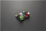
Beetle Shield
SKU:DFR0285
Contents
1 Introduction
2 Specification
3 Attaching the Beetle controller to the Beetle shield
4 Pinout
5 Projects and products using the Beetle shield
Introduction
The Beetle shield is designed to attach a Beetle controller for easy connecting servos and sensors.
�Specification
Operating voltage: 3 - 5V
Compatible with DFRobot Beetle
Attaching the Beetle controller to the Beetle shield
Note: For Beetle shield versions lower than v1.1 the label for D9 and D11 is switched. The pin
labeled with D9 on the shield goes to D11 on the Beetle and D11 on the shield is going to D9 on the
Beetle. Please take the labels on the Beetle controller as the right ones. We have fixed this error in
v1.1
To attach the Beetle to the shield it requires some soldering work. Align the holes of the Beetle with
the pins on the shield. Make sure the Beetle controller is showing the microcontroller chip and the
USB socket facing up to ensure the correct polarity and pin assignment after soldering it to the
shield.
Beetle controller on Beetle shield (click to enlarge)
Push the Beetle down onto the pins and let the pins looking out for ca. 1mm. Solder the eight pins at
the pads of the Beetle using a soldering iron or soldering gun.
Soldering the Beetle controller on the Beetle shield
�Pinout
The shield is a breakout of the six pins D9, D10, D11 and A0, A1, A2 as well the two power pins +
and – besides the USB socket. The other two power pads on the other side of the Beetle are not
connected with the shield but you still can use them as a power source since they are routed to the
power lines on the Beetle itself.
Beetle shield pinout (click to enlarge)
After soldering the Beetle on the shield you may power it up by connecting a power source from 3V
to 5V with the power pins labeled with + and - on the Beetle shield. With switching the power on by
pressing the button the LED should light up to confirm the power is witched on. At the same time the
LED on the Beetle should light up too. That is the proof that you successful finished the soldering
task.
Now you might program your Beetle controller by connecting a Micro USB cable with the USB
socket of the Beetle.
The pins on the Beetle shield are arranged to connect with standard servo and sensor connectors.
The order is as followed:
Signal VCC GND
Note: If you want to use the additional pins (RX, TX, SCL and SDA) broken out to the Pads on the
backside of the Beetle controller you might need to solder them before you solder the Beetle to the
shield.
�Powered By DFRobot © 2008-2017
�
很抱歉,暂时无法提供与“DFR0285”相匹配的价格&库存,您可以联系我们找货
免费人工找货- 国内价格 香港价格
- 1+26.089011+3.26008
- 国内价格 香港价格
- 1+8.771631+1.09610
