Page 1 of 8
SparkFun Blocks for Intel® Edison - 9 Degrees
of Freedom Block
Introduction
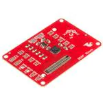
The 9 Degrees of Freedom Block for the Intel® Edison uses the LSM9DS0
9DOF IMU for full-range motion sensing. Use this Block to determine
orientation, acceleration, and compass headings. The LSM9DS0 combines
a 3-axis accelerometer, a 3-axis gyroscope, and a 3-axis magnetometer.
The IMU is connected to the Edison through the I2C bus.
9 Degree of Freedom Block
Suggested Reading
If you are unfamiliar with Blocks, take a look at the General Guide to
Sparkfun Blocks for Intel Edison.
Other tutorials that may help you on your Edison adventure include:
• Powering Your Project
• Battery Technologies
• Connector Basics
Board Overview
�Page 2 of 8
The 9DOF Block has a lot of jumpers on it, but you can use it without
understanding or changing any of them. Here’s a description of each one:
A (INT2) - Accelerometer/magnetometer interrupt 2. This pin can be
configured to change on a number of different conditions. See datasheet pp
58 and 65-67 for more details on configuring the device. Closing this jumper
with a solder blob connects the INT2 pin on the LSM9DS0 to GPIO 49 on
the Edison.
B (INT1) - Accelerometer/magnetometer interrupt 1. This pin can be
configured to change on a number of different conditions. See datasheet pp
58 and 63-65 for more details on configuring the device. Closing this jumper
with a solder blob connects the INT2 pin on the LSM9DS0 to GPIO 48 on
the Edison.
C (DRDYG) - Data Ready, gyroscope. Closing this jumper connects the pin
to GPIO 47. See datasheet page 43 for information on configuring this pin.
D (INTG) - Gyroscope interrupt. This pin can be configured to change on a
number of different conditions. Closing this jumper will connect the pin to
GPIO 46. See datasheet pages 43 and 47-50 for information on configuring
this pin.
E (DEN) - Data enable, gyroscope. Enable or !pause data collection. This
pin can safely be ignored. Closing this jumper allows processor control of
data collection via GPIO 165.
F (CLOCK/DATA) - I/O interface selection jumpers. Default setting is to
I2C1 but cutting the small trace visible between the two upper pads of each
jumper and closing the bottom two pads with a solder blob allow the user to
route control to SPIDEV2. SPI is currently an unsupported feature and
will likely be removed from a future revision.
G (CSG) - SPI chip select, gyroscope. Closing this jumper connects the
signal to GPIO 111 on the Edison, which is FS0 on SPIDEV2. The CS pin
can be either handled manually or by the driver. SPI is currently an
unsupported feature and will likely be removed from a future revision.
H (CSXM) - SPI chip select, accelerometer/magnetometer. Closing this
jumper connects the signal to GPIO 110 on the Edison, which is FS1 on
SPIDEV2. The CS pin can be either handled manually or by the driver. SPI
is currently an unsupported feature and will likely be removed from a
future revision.
I (SDOG) - SPI serial data out (MISO), gyroscope. SPI is currently an
unsupported feature and will likely be removed from a future revision.
J (SDOXM) - Serial data out (MISO), accelerometer/magnetometer. SPI is
currently an unsupported feature and will likely be removed from a
future revision.
�Page 3 of 8
K (I2C PUs) - Pull-up resistor removal for I2C SDA and SCL lines. Most
likely, you won’t want to remove these resistors from the system; however,
if you have a lot of devices on the I2C bus, you may need to remove some
of the pull-ups from the lines to reduce the pull-up strength.
L (CS PUs) - Pull-up resistor removal for SPI chip select lines. Normally
pull-up resistors should be left in place. SPI is currently an unsupported
feature and will likely be removed from a future revision.
M (SDOG PU) - Closed by default, this pin sets the I2C address used by the
gyroscope. When closed, the gyroscope’s address is 0x6b. When open,
jumper SDOG PD (labeled ‘O’ above) must be closed.
N (SDOXM PU) - Closed by default, this pin sets the I2C address used by
the magnetometer/accelerometer. When closed, their collective address is
0x1d. When open, jumper SDOXM PD (labeled ‘P’ above) must be closed.
O (SDOG PD) - Open by default, this pin sets the I2C address used by the
gyroscope. When closed, the gyroscope’s address is 0x6a.
P (SDOXM PD) - Open by default, this pin sets the I2C address used by the
magnetometer/accelerometer. When closed, their collective address is
0x1e.
Connecting the 9 DOF Block
To use the 9 DOF Block simply attach an Intel Edison to the back of the
board or add it to your current stack. Blocks can be stacked without
hardware but it leaves the expansion connectors unprotected from
mechanical stress.
9 DOF Block Installed
We have a nice Hardware Pack available that gives enough hardware to
secure three blocks and an Edison.
Intel Edison Hardware Pack
�Page 4 of 8
NOTE: The 9 DOF Block does not have console access or a voltage
regulator. It is recommended to use a console communication block in
conjunction with this block like ones found in the General Guide to Sparkfun
Blocks for Intel Edison.
C++ Code Examples
We’re assuming that you’re using the Eclipse IDE as detailed in our Beyond
Arduino tutorial. If you aren’t, you’ll need to read over that tutorial to get up
to speed.
Getting Started
Follow the instructions in the programming tutorial to create a new project
named “SparkFun_9DOF_Edison_Block_Example”. Once you’ve created
the project, open the project files on disk (hint: you can find the path to the
project by choosing “Properites” from the project menu), and copy the three
source files found in the Edison 9DOF Block CPP library GitHub repository
into the “src” directory.
D O W N L O A D A ZI P FIL E O F T H E RE P O S I T O R Y
Code
Everything you need to know is in the comments.
�Page 5 of 8
#include "mraa.hpp"
#include
#include
#include "SFE_LSM9DS0.h"
using namespace std;
int main()
{
LSM9DS0 *imu;
imu = new LSM9DS0(0x6B, 0x1D);
// The begin() function sets up some basic parameters and tu
rns the device
// on; you may not need to do more than call it. It also re
turns the "whoami"
// registers from the chip. If all is good, the return valu
e here should be
// 0x49d4. Here are the initial settings from this functio
n:
// Gyro scale:
245 deg/sec max
// Xl scale:
4g max
// Mag scale:
2 Gauss max
// Gyro sample rate: 95Hz
// Xl sample rate:
100Hz
// Mag sample rate:
100Hz
// These can be changed either by calling appropriate functi
ons or by
// pasing parameters to the begin() function. There are nam
ed constants in
// the .h file for all scales and data rates; I won't repro
duce them here.
// Here's the list of fuctions to set the rates/scale:
// setMagScale(mag_scale mScl)
setMagODR(mag_odr mRat
e)
// setGyroScale(gyro_scale gScl)
setGyroODR(gyro_odr gRa
te)
// setAccelScale(accel_scale aScl) setGyroODR(accel_odr aR
ate)
// If you want to make these changes at the point of callin
g begin, here's
// the prototype for that function showing the order to pas
s things:
// begin(gyro_scale gScl, accel_scale aScl, mag_scale mSc
l,
//
gyro_odr gODR, accel_odr aODR, mag_odr mOD
R)
uint16_t imuResult = imu>begin();
cout
很抱歉,暂时无法提供与“DEV-13033”相匹配的价格&库存,您可以联系我们找货
免费人工找货