Skywire click
PID: MIKROE-2405
Weight: 30 g
Condition: New product
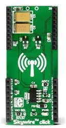
Skywire™ click is an adapter click, which hosts NimbeLink/Skywire™ cellular modems (using
stacking headers) to MikroElektronika development boards. It carries the MCP1826 low dropout
regulator from Microchip.
NOTE: the Skywire™ modem and the Thermo 3 click are not included in this offer.
Table of contents
1. Additional mikroBUS™ socket
2. Skywire cellular modems
3. Key features
�Skywire™ click is an adapter click, which hosts NimbeLink/Skywire™ cellular
modems (using stacking headers) to MikroElektronika development boards. It carries
the MCP1826 low dropout regulator from Microchip. Skywire™ click is designed to run either
on 3.3V or 5V power supply. The click communicates with the target MCU over UART
interface, and the following mikroBUS™ pins: PWM, AN, INT, RST, CS.
NOTE: the Skywire™ modem and the Thermo 3 click are not included in this offer.
Additional mikroBUS™ socket
Skywire™ click has the capability to host an additional mini sized click board™. It also has its
own power supply to make the needed voltage for the modules.
Skywire cellular modems
Skywire™ cellular modems are the smallest on the market today. This product family from
NimbeLink covers everything from 2G and 3G to LTE. They all share the same footprint and
pinout, and are flexible for implementation.
Key features
MCP1826 LDO regulator
o 1000 mA Output Current Capability
o Output voltage range of 0.8V to 5.0V
Additional socket for a mini sized click board™
Interface: UART
3.3V or 5V power supply
SPECIFICATION
Product Type
On-board
modules
Adapter
MCP1826 LDO regulator
Additional socket for mini sized click board™, MCP1826 LDO regulator,
3.3V or 5V power supply
Adapts Nimbelink/Skywire modules with MikroElektronika development
Key Benefits
systems
Interface
UART
Power Supply
3.3V or 5V
Compatibility
mikroBUS
Click board size L (57.15 x 25.4 mm)
Key Features
�Pinout diagram
This table shows how the pinout on Skywire click corresponds to the pinout on the mikroBUS™
socket (the latter shown in the two middle columns).
Notes
Pin
Pin
Notes
mikroBUStm
Enable EN 1 AN
RESET RST 2 RST
PWM 16 CTS Clear To Send
INT 15 AD1_J ADC IN
Request To Send RTS 3 CS
TX 14
TX UART transmit
Not connected NC 4 SCK
RX 13
RX UART receive
Not connected NC 5 MISO SCL 12
NC Not connected
Not connected NC 6 MOSI SDA 11
NC Not connected
Power supply +3.3V 7 3.3V
5V 10 +5V Power supply
Ground GND 8 GND GND 9 GND Ground
Programming
The following code snippet starts the main function in the Skywire application.
This is a simple main function, which excepts a call and replies with an SMS to caller. The
content of the SMS is the current temperature measurement in degrees Celsius.
01: void main()
02: {
03:
measure_f = false;
04:
system_init();
05:
skywire_power_on();
06:
at_init( rsp_handler, UART3_Write, buffer, sizeof( buffer ) );
07:
at_cmd_save( "+CLCC", 1000, NULL, NULL, NULL, callerid_handler );
// Assigning caller ID handler
08:
at_cmd_single( "AT" );
09:
at_cmd_single( "AT+CSCS="GSM"" );
10:
at_cmd_single( "AT+CMGF=1" );
�11:
while( 1 )
12:
{
13:
at_process();
14:
15:
if( measure_f )
16:
{
17:
measure_temp();
18:
at_cmd_single( "AT+CLCC" );
19:
at_cmd_single( "ATH" );
20:
Delay_ms( 2000 );
// Delay needed after ATH
21:
reply_to_caller();
22:
measure_f = false;
23:
}
24:
}
25: }
Jumpers and settings
The following table describes the functions of the onboard jumpers.
Designator Name
Default
Position
Default
Option
Description
JP1
PWR.SEL.
Left
3.3V
Power Supply Voltage Selection 3.3V/5V, left position
3.3V, center position 5V
ADC1
ADC1
Populated
3.3V
Connects ADC1 pin of the modem to the mikroBUS
pin
Copyright © 1998 ‐ 2017. MikroElektronika d.o.o.
�
很抱歉,暂时无法提供与“MIKROE-2405”相匹配的价格&库存,您可以联系我们找货
免费人工找货- 国内价格 香港价格
- 1+203.307631+26.30327