BIG 7-SEG R click
1
BIG 7-SEG R click
BIG 7-SEG R click
BIG 7-SEG R click
IC/Module
Interface
SC10-21SRWA datasheet
[1]
74HC595 datasheet
[2]
SPI
Power supply 3.3V or 5V
Product page BIG 7-SEG R click [3]
Schematic
BIG 7-SEG R click schematic
[4]
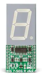
BIG 7-SEG R click is what you need if you want to add a seven-segment LED display to your project. This click
features an SC10-21SRWA 7-segment display. Communication between the MCU and the SC10-21SRWA display
is established via serial-IN, parallel-OUT shift register 74HC595 IC.
The click runs on either a 3.3V or 5V power supply and communicates with the target MCU over an SPI interface.
Features and usage notes
Display
The click displays letters, numbers and symbols in highly readable form. It can be used in any simple interface and
combined with other click boards. The color of the displayed character is red, as the R in the name of the click states.
Seven segment displays use different combinations of the segments to display symbols, most commonly Arabic
numerals.
Each segment is connected to one of the pins on the 74HC595 IC.
�BIG 7-SEG R click
2
Light intensity
The light intensity on the display is controlled via the PWM pin on the board.
Application
Adding a seven-segment LED display to your device with SPI interface. It can be used for digital clocks, vending
machine displays, electronic meters and many other devices.
Key features
• SC10-21SRWA display
• 1.0 inch digit height
• Standard: gray face, white segment
• Low current operation
• Serial-IN, parallel-OUT shift register 74HC595 IC
• Interface: SPI
• 3.3V or 5V power supply
Pinout diagram
This table shows how the pinout on BIG 7-SEG R click corresponds to the pinout on the mikroBUS™ socket (the
latter shown in the two middle columns).
Notes
Pin
Pin
Notes
mikroBUStm
Not connected
NC
1 AN
Master Reset for 74HC595
MR
2 RST
Latch for 74HC595
X PWM 16 PWM Display light intensity control
INT
15 NC
Not connected
LAT 3 CS
TX
14 NC
Not connected
Clock for 74HC595
CLK 4 SCK
RX
13 NC
Not connected
Serial Data from 74HC595 to
MCU
DSO 5 MISO
SCL
12 NC
Not connected
Serial Data from MCU to
74HC595
DSI
6 MOSI
SDA
11 NC
Not connected
7 +3.3V
+5V
10 5V
Data line when interfaced with 5V MCU and also power supply pin for
display and the whole click hardware
Data line when interfaced with 3.3V
3.3V MCU
Ground
GND 8 GND
GND 9
GND
Ground
Jumpers and settings
Information about onboard jumpers:
Designator Name
Default
Position
Default
Option
Description: describe the use + list all options with respective descriptions
JP1
Left
3.3V
Logic Level Selection toward host mcu 3.3V/5V, left position 3.3V, right position
5V
Logic
level
�BIG 7-SEG R click
3
Programming
This demo is using BIG 7-SEG R click board to display characters in an endless loop, with fixed time interval whilst
changing its PWM duty.
• Operating Voltage Range: 2.0 to 6.0 V
• Operating Temperature: – 55 to 125 C
This example for STM32F107VC MCU ( EasyMx PRO v7 for ARM ), resets and initializes the BIG 7-SEG R click
board takes characters from the static array and displays them while changing PWM duty cycle, all in an endless
loop.
extern char dig_array[MAX_CHARACTERS];
// Variables
unsigned short counter;
unsigned int luminosity;
unsigned int pwm_period;
int8_t valid;
char demo_array[20] =
{ 'M', 'I', 'K', 'R', 'O',
'E', 'L', 'E', 'K', 'T', 'R', 'O', 'N', 'I', 'K', 'A',
'2', '0', '1', '6'
};
void main()
{
// MCU Init
GPIO_Digital_Output(&GPIOD_ODR, _GPIO_PINMASK_13);
PORTD.B13 as digital input
GPIO_Digital_Output(&GPIOC_ODR, _GPIO_PINMASK_2);
PORTC.B2 as digital output
// Set
// Set
// SPI Init
SPI3_Init_Advanced( _SPI_FPCLK_DIV16, _SPI_MASTER | _SPI_8_BIT |
_SPI_CLK_IDLE_LOW | _SPI_FIRST_CLK_EDGE_TRANSITION |
_SPI_MSB_FIRST | _SPI_SS_DISABLE | _SPI_SSM_ENABLE |
_SPI_SSI_1, &_GPIO_MODULE_SPI3_PC10_11_12 );
// PWM Init
pwm_period = PWM_TIM5_Init(5000);
// PWM Init
on 5kHz
PWM_TIM5_Set_Duty(100, _PWM_NON_INVERTED, _PWM_CHANNEL1);
PWM_TIM5_Start(_PWM_CHANNEL1, &_GPIO_MODULE_TIM5_CH1_PA0);
// 74HC595 Init
HC595_LAT = 0;
HC595_RES = 0;
HC595_reset();
�BIG 7-SEG R click
// Init counter and segment luminosity
counter = 0;
luminosity = 0;
// Endless loop
while (1)
{
valid = seg_7_display(demo_array[counter]);
PWM_TIM5_Set_Duty(100 + luminosity, _PWM_NON_INVERTED,
_PWM_CHANNEL1);
delay_ms(750);
luminosity += 100;
counter++;
if (counter == 20)
counter = 0;
if (luminosity == 4000)
luminosity = 0;
}
}
Resources
•
•
•
•
•
BIG 7-SEG R click schematic [4]
SC10-21SRWA datasheet [1]
74HC595 datasheet [2]
Libstock Library [5]
mikroBUS™ standard specifications [6]
References
[1]
[2]
[3]
[4]
[5]
[6]
http:/ / www. kingbrightusa. com/ images/ catalog/ SPEC/ SC10-21SRWA. pdf
http:/ / www. ti. com/ lit/ ds/ symlink/ sn74hc595. pdf
https:/ / shop. mikroe. com/ click/ display/ big-7-seg-r
http:/ / cdn-docs. mikroe. com/ images/ a/ a1/ BIG_7-SEG_R_click_schematic. pdf
http:/ / libstock. mikroe. com/ projects/ view/ 1979/ big-7-seg-r-click
http:/ / download. mikroe. com/ documents/ standards/ mikrobus/ mikrobus-standard-specification-v200. pdf
4
�Article Sources and Contributors
Article Sources and Contributors
BIG 7-SEG R click Source: http://docs.mikroe.com/index.php?oldid=3089 Contributors: Lana.vulic
Image Sources, Licenses and Contributors
File:Big-7-seg-r-click-front.jpg Source: http://docs.mikroe.com/index.php?title=File:Big-7-seg-r-click-front.jpg License: unknown Contributors: Lana.vulic
File:mikrobus logo.png Source: http://docs.mikroe.com/index.php?title=File:Mikrobus_logo.png License: unknown Contributors: Vojislav.gvozdic
License
Creative Commons Attribution
https:/ / creativecommons. org/ licenses/ by/ 4. 0/
5
�
很抱歉,暂时无法提供与“MIKROE-2269”相匹配的价格&库存,您可以联系我们找货
免费人工找货