Page 1 of 2
Timer click
From MikroElektonika Documentation
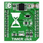
Timer click carries Maxim’s DS1682 total elapsed time recorder. The main feature of the IC
is its elapsed time conter (ETC) used in conjunction with the ALARM pin. Whenever the
EVENT pin is held high, the ETC will track time in quarter second resolution. Once the
EVENT pin is set to logic low, the time data will be written in the IC’s non volatile
EEPROM. The next time the EVENT pin is pulled high, the timer will pick up where it left
and continue measuring accumulated time. The upper limit is 34 years. In practical
applications, the ALARM pin will be utilized to set off a flag once a certain threshold of
accumulated time is reached. The alarm flag is one time programmable. The board
communicates with the target MCU through the mikroBUS™ I2C interface, with two
additional pins: ALARM (in place of default INT) and EVENT (in place of RST). Designed
to use either a 3.3V or a 5V power supply only.
Timer click
Features and usage notes
Here’s a description of individual pins
from the DS1682 IC, taken from the
official data sheet. Each of these is
accessible through the mikroBUS™ pin
EVENT Event Input. The EVENT pin is
Timer click
the input the DS1682 monitors to
IC/Module DS1682
determine when an event occurs. When
the pin is pulled high, the contents of the
(http://datasheets.maximintegrated.com/en/ds/DS1682.pdf)
EEPROM are transferred to the ETC and
Interface I2C, EVENT, ALARM
the oscillator starts. The ETC begins to
3.3V, 5V
Power
count in quarter-second increments.
When the EVENT pin falls to logic 0, the supply
Schematic also available in PDF (http://cdnevent counter increments, and the event
docs.mikroe.com/images/0/06/SchematicWebsite
www.mikroe.com/click/timer
counter, ETC, and user-memory data are
TIMER_click_v101.pdf)
(http://www.mikroe.com/click/timer)
stored in the EEPROM array. When the
EVENT pin changes states, the 2-wire
bus is unavailable for communications for tEW (falling) and tER (rising). The EVENT input is also deglitched (tG) to prevent short noise spikes from triggering
an event.
ALARM Active-Low Alarm Output. The DS1682 monitors the values in the ETC for the programmed value in the alarm register. When the ETC matches the
alarm value, the alarm flag (AF) is set. Once set, the alarm flag cannot be reset. See the operating descriptions for the AOS and AP bits for details about the
operation of the ALARM pin.
SCL 2-Wire Serial-Clock Input. The SCL pin is the serial-clock input for the 2-wire synchronous communications channel. The SCL pin is an input that requires
an external pullup resistor.
SDA 2-Wire Input/Output. The SDA pin is the data input/output signal for the 2-wire synchronous communications channel. The SDA pin is an open-drain I/O,
which requires an external pullup resistor.
N.C. No Connection. These pins are not connected internally.
Vcc +2.5V to +5.5V Input Supply
To switch between 3.3V and 5V power supplies, use the onboard jumper.
Programming
Code snippet demonstrates how the Timer click counts the elapsed time, as well as the number of events on the EVT pin
1
2
3
4
5
6
7
8
9
10
11
12
13
14
15
16
//TIMER click on socket 1
#include "timer_hw.h"
//#define CountFromZero
// TFT module connections
unsigned int TFT_DataPort at GPIOE_ODR;
sbit TFT_RST at GPIOE_ODR.B8;
sbit TFT_RS at GPIOE_ODR.B12;
sbit TFT_CS at GPIOE_ODR.B15;
sbit TFT_RD at GPIOE_ODR.B10;
sbit TFT_WR at GPIOE_ODR.B11;
sbit TFT_BLED at GPIOE_ODR.B9;
// End TFT module connections
�Page 2 of 2
17
18
19
20
21
22
23
24
25
26
27
28
29
30
31
32
33
34
35
36
37
38
39
40
41
42
43
44
45
46
47
48
49
50
51
52
53
54
55
56
57
58
59
60
61
62
63
64
65
66
67
68
69
70
71
72
sbit TIMER_EVT at GPIOD_ODR.B1;
sbit TIMER_ALM at GPIOC_IDR.B1;
char text[24];
unsigned long ETC;
unsigned int EC;
//elapsed time counter
void Display_Init(){
TFT_Init_ILI9341_8bit(320, 240);
TFT_BLED = 1;
TFT_Set_Pen(CL_AQUA, 1);
TFT_Fill_Screen(CL_AQUA);
TFT_Set_Font(TFT_defaultFont, CL_BLACK, FO_HORIZONTAL);
TFT_Set_Pen(CL_AQUA, 1);
TFT_Set_Brush(1, CL_AQUA, 0, LEFT_TO_RIGHT, CL_AQUA, CL_AQUA);
}
TFT_Write_Text("Event count: ",10,10);
TFT_Write_Text("Time count: ",10,50);
void MCU_Init() {
GPIO_Digital_Output(&GPIOD_BASE, _GPIO_PINMASK_1);
GPIO_Digital_Input(&GPIOC_BASE, _GPIO_PINMASK_1);
TIMER_EVT = 1;
I2C1_Init_Advanced(400000, &_GPIO_MODULE_I2C1_PB67);
delay_ms(200);
}
void main() {
MCU_Init();
timer_hal_init(DS1682_I2C_Adr);
Display_Init();
#ifdef CountFromZero
timer_set_ec_value(0);
timer_set_etc_value(0);
TIMER_EVT = 0;
delay_ms(100);
TIMER_EVT = 1;
delay_ms(100);
#endif
while(1) {
delay_ms(2000);
TFT_Rectangle(100,10,200,40);
TFT_Rectangle(80,50,200,80);
//Event counter
EC = timer_Get_ec_Value();
WordToStr(EC,text);
TFT_Write_Text(text,100,10);
//Time counter - in quarter seconds
ETC = timer_get_etc_value();
LongWordToStr(ETC,text);
TFT_Write_Text(text,100,50);
}
}
Code examples that demonstrate the usage of Timer click with MikroElektronika hardware, written for mikroC for ARM, FT90x, and PIC are available on
Libstock (http://libstock.mikroe.com/projects/view/1822/timer-click-library).
Resources
- Timer click Libstock example (http://libstock.mikroe.com/projects/view/1822/timer-click-library)
- Vendor’s data sheet (http://datasheets.maximintegrated.com/en/ds/DS1682.pdf)
Retrieved from "http://docs.mikroe.com/index.php?title=Timer_click&oldid=381"
◾ This page was last modified on 17 June 2016, at 19:21.
◾ Content is available under Creative Commons Attribution unless otherwise noted.
http://docs.mikroe.com/index.php?title=Timer_click&printable=yes
7/11/2016
�