2. Soldering the headers
Before using your click™ board, make sure
to solder 1x8 male headers to both left
and right side of the board. Two 1x8 male
headers are included with the board in
the package.
MPU 9DOF click
1
4. Essential features
™
2
3
Turn the board upside down so that
the bottom side is facing you upwards.
Place shorter pins of the header into the
appropriate soldering pads.
Turn the board upward again. Make sure
to align the headers so that they are
perpendicular to the board, then solder
the pins carefully.
1. Introduction
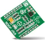
MPU 9DOF click™ carries the MPU–9150
SiP (System in Package), which is the
world’s first 9-axis MotionTracking device.
The device comprises two chips: one is
the MPU–6050 that contains a 3-axis
accelerometer, a 3-axis gyroscope, and a
DMP (digital motion processor); the other
is AK8975, a 3-axis digital compass.
MPU 9DOF click™ communicates with
the target board through mikroBUS™ I2C
(SCL, SDA), INT and RST (FSYNC) lines. It’s
designed to use a 3.3V power supply only.
3. Plugging the board in
Once you have soldered the headers your
board is ready to be placed into the desired
mikroBUS™ socket. Make sure to align the
cut in the lower-right part of the board with
the markings on the silkscreen at the
mikroBUS™ socket. If all the pins
are aligned correctly, push the
board all the way into the socket.
The MPU–9150 aboard MPU 9DOF click™ is
designed for the low power, low cost and
high performance requirements of consumer
electronics equipment and wearable
sensors. The ability to track motion in
free space also makes MPU 9DOF click™ a
suitable sensor when designing remote
controlled quadcopters. The Tri-Axis gyro
has a sensitivity up to 131 LSBs/dps and a
full-scale range of ±250, ±500, ±1000, and
±2000dps; the Tri-Axis accelerometer with
a programmable full scale range of ±2g, ±4g,
±8g and ±16g; and the tri-axis compass has
a full scale range of ±1200µT.
click
™
BOARD
www.mikroe.com
MPU 9DOF click™ manaul
ver. 1.00
0 100000 027325
�5. MPU 9DOF click™ board schematic
6. Zero-Ohm jumpers
VCC3.3
REGOUT
R1
2K2
LD1
VCC3.3
C2
100nF
MPU 9DOF click™ has two jumpers (zero-Ohm
resistors). FSYNC enables or disables the
interrupt function on the FSYNC (RST)
mikroBUS™ pin. I2C ADD allows you to select
between the available I2C addresses.
VCC3.3
C3
100nF
C4
10uF
C1
VCC3.3
CLKIN
NC
VDD
MPU-9150
NC
NC
AUX_DA
SA0
REGOUT
FSYNC
INT
7
8
9
10
11
12
AUX_CL
VLOGIC
AD0/SDO
REGOUT
FSYNC
INT
1
2
3
4
5
6
VCC3.3
VCC3.3
Once you have done all the necessary
preparations, it’s time to get your click™ board
up and running. We have provided examples
for mikroC™, mikroBasic™ and mikroPascal™
compilers on our Libstock website. Just
download them and you are ready to start.
2.2nF
U1
R3
4K7
SDA
SCL
NC
NC
CPOUT
NC
24
23
22
21
20
19
SDA
SCL
7. Code examples
VCC3.3
GND
GND
NC
GND
NC
VDD
18
17
16
15
14
13
FSY
AN
RST
CS
SCK
MISO
MOSI
+3.3V
GND
PWM
INT
TX
RX
SCL
SDA
+5V
GND
MIKROBUS DEVICE CONN.
R2
R4
4K7
INT
SCL
SDA
FSY
FSYNC
FSY EN/DIS
J1A
.com
VCC3.3
SA0
ADDR SEL
100K
8. Support
J2A
MikroElektronika assumes no responsibility or liability for any errors or inaccuracies that may appear in the present document.
Specification and information contained in the present schematic are subject to change at any time without notice. Copyright © 2014 MikroElektronika. All rights reserved.
MikroElektronika offers free tech support
(www.mikroe.com/support) until the end
of the product’s lifetime, so if something
goes wrong, we’re ready and willing to help!
�
很抱歉,暂时无法提供与“MIKROE-1996”相匹配的价格&库存,您可以联系我们找货
免费人工找货