Page 1 of 3
Compass 2 click
From MikroElektonika Documentation
Revision as of 16:23, 24 June 2016 by Srdjan.misic (talk | contribs)
(diff) ← Older revision | Latest revision (diff) | Newer revision → (diff)
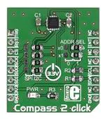
Compass 2 click carries an AK8963 3-axis electronic compass. The high sensitivity sensor is based
on the Hall effect. The built-in ADC converter can be set up at either 14 or 16 bit resolution, for
each of the 3 axes. The sensitivity is 0.6µT/LSB typ. at 14-bit, and 0.15µT/LSB at 16-bit. Compass
2 click communicates with the target MCU through either through the I2C or SPI interface, with an
added INT pin. Onboard jumpers enable you to switch between two interfaces. The board is
designed to use a 3.3 power supply only.
Compass 2 click
Features and usage notes
The AK8964 has several operating modes
which can be configured by setting a specific
register (CNTL1) to certain values. The
following is a list of available operating modes
with partial descriptions (to give you an
overview). The configuration details are
available on page 13 of the official data sheet,
while the complete descriptions
(1) Power-down mode
Schematic also available in PDF (http://cdndocs.mikroe.com/images/1/1a/Compass_2_click_sche
Power to almost all internal circuits is turned
off. All registers are accessible in power-down
mode. However, fuse ROM data cannot be read
correctly. Data stored in read/write registers are
remained. They can be reset by soft reset.
(2) Single measurement mode
When single measurement mode (MODE[3:0]=“0001”) is set, sensor is measured, and after sensor
measurement and signal processing is finished, measurement data is stored to measurement data
registers (HXL to HZH), then AK8963 transits to power-down mode automatically.
Compass 2 click
IC/Module AK8963
(http://www.akm.com/akm/en/product/datasheet1/?
partno=AK8963)
Interface
SPI, I2C, INT
Power
3.3V
supply
Website
www.mikroe.com/click/compass-2
(http://www.mikroe.com/click/compass-2)
(3) Continuous measurement mode 1 and 2
When continuous measurement mode 1 (MODE[3:0]=“0010”) or 2 (MODE[3:0]=“0110”) is set, sensor is measured periodically at 8Hz or 100Hz respectively.
When sensor measurement and signal processing is finished, measurement data is stored to measurement data registers (HXL ~ HZH) and all circuits except for
the minimum circuit required for counting cycle lentgh are turned off (PD).
(4) External trigger measurement mode
When external trigger measurement mode (MODE[3:0]=“0100”) is set, AK8963 waits for trigger input. When a pulse is input from TRG pin, sensor
measurement is started on the rising edge of TRG pin. When sensor measurement and signal processing is finished, measurement data is stored to measurement
data registers (HXL to HZH) and all circuits except for the minimum circuit required for trigger input waiting are turned off (PD state).
(5) Fuse ROM access mode
Fuse ROM access mode is used to read Fuse ROM data. Sensitivity adjustments for each axis is stored in fuse ROM.
Compass 2 click has both SPI and I2C interfaces. The active interface is configured with onboard jumpers. If you use I2C, an additional jumper will allow you to
set the I2C address.
Programming
This code snippet initiates Compass 2 with I2C communication, and reads out the heading value, along with a direction, ( N, NE, E, etc ) from the module to a
UART terminal every 100 ms.
1
2
3
4
5
6
7
8
9
10
#include
#include "compass2_hw.h"
sbit COMPASS2_CS at GPIOD_ODR.B13;
void system_setup( bus_mode_t mode, uint8_t addr );
float mRes;
// scale resolutions per LSB for the sensors
uint8_t asax, asay, asaz;
float adjusted_ASAX, adjusted_ASAY, adjusted_ASAZ;
�Page 2 of 3
11
12
13
14
15
16
17
18
19
20
21
22
23
24
25
26
27
28
29
30
31
32
33
34
35
36
37
38
39
40
41
42
43
44
45
46
47
48
49
50
51
52
53
54
55
56
57
58
59
60
61
62
63
64
65
66
67
68
69
70
71
72
73
74
75
76
77
78
79
80
81
82
83
84
85
86
87
88
89
90
91
92
93
94
95
96
97
98
99
100
101
102
103
104
105
106
107
108
109
110
111
112
113
114
115
116
117
118
119
120
121
122
123
124
125
126
float heading, adjusted_MX, adjusted_MY, adjusted_MZ, magbias[3];
int16_t mx, my, mz;
char text[20] = { 0 };
void main()
{
// Local Declarations
uint8_t address = 0x0F;
bus_mode_t my_mode = I2C;
float heading = 0;
char uart_text[5] = { 0 };
system_setup( my_mode, address );
while(1)
{
compass2_get_all_values( &mx, &my, &mz );
heading = compass2_get_compass_heading( mx, my, mz );
if( heading < 0 )
heading += 360;
UART1_Write_Text( "Heading: " );
FloatToStr( heading, text );
UART1_Write_Text( text );
UART1_Write_Text( " Direction: " );
if( heading >= 330 || heading = 300 && heading = 240 && heading = 210 && heading
很抱歉,暂时无法提供与“MIKROE-2264”相匹配的价格&库存,您可以联系我们找货
免费人工找货