Signal Relay click
1
Signal Relay click
Signal Relay click
Signal Relay click
IC/Module
Interface
PCB GV5-1 datasheet
[1]
AN, RST, CS and PWM
Power supply 5V
Product page shop.mikroe.com/click/miscellaneous/signal-relay [2]
Schematic
Signal Relay click schematic
[3]
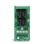
Signal Relay click carries four ultra-small GV5-1 PCB relays from Omron and runs on a 5V power supply. The
click communicates with the target MCU over the following mikroBUS pins: AN, RST, CS and PWM.
Features and usage notes
Maximum continuous current
The relay contacts are designed for a maximum of 1A of continuous current. The Signal Relay click board is
configured so that the switch circuit supply a maximum of 24VAC/30VDC voltage of a power supply source.
LED
Each GV5-1 relay has its own LED on the board that signalizes whether the relays is switched on or off.
Application
ON/OFF control in various home automation devices, like alarm units, lamps, heaters, etc. It can also be used for
energizing coils of bigger relays and contactors in industrial AC schemes (12/24V).
�Signal Relay click
2
Key features
• GV5-1 relay
• Power switching from 1 mA to 1 A
• 150 mW nominal coil power consumption
• Maximum contact resistance 100 mΩ
• 4 pairs of screw terminals
• Interface: AN, RST, CS and PWM pin
• 5V power supply
Pinout diagram
This table shows how the pinout on Signal Relay click corresponds to the pinout on the mikroBUS™ socket (the
latter shown in the two middle columns).
Notes
Pin
Pin
Notes
mikroBUStm
GPIO for switch ON/OFF RELAY 1 RE1
1 AN
X PWM 16 RE4
GPIO for switch ON/OFF RELAY 2 RE2
2 RST
INT
15 NC
Not connected
GPIO for switch ON/OFF RELAY 3 RE3
3 CS
TX
14 NC
Not connected
Not connected
NC
4 SCK
RX
13 NC
Not connected
Not connected
NC
5 MISO
SCL
12 NC
Not connected
Not connected
NC
6 MOSI
SDA
11 NC
Not connected
Not connected
NC
7 +3.3V
+5V
10 5V
Power supply
Ground
GND 8 GND
GND 9
GPIO for switch ON/OFF RELAY 4
GND Ground
LEDs and connectors
The table below explains onboard LEDs and connectors.
Designator Name
Type (LED, BUTTON…)
Description
LD1
PWR
LED
Power LED
LD2
OUT1
LED
INDICATOR OUTPUT 1 ON (RELAY1 ON)
LD3
OUT2
LED
INDICATOR OUTPUT 2 ON (RELAY2 ON)
LD4
OUT3
LED
INDICATOR OUTPUT 3 ON (RELAY3 ON)
LD5
OUT4
LED
INDICATOR OUTPUT 4 ON (RELAY4 ON)
CN1
OUTPUT TERMINAL 8-POLE TERMINAL BLOCK CONNECTOR RELAY1 CONTACT ENDS (RE1 - CE1)
2.54MM PITCH
RELAY2 CONTACT ENDS (RE2 - CE2)
RELAY3 CONTACT ENDS (RE3 - CE3)
RELAY4 CONTACT ENDS (RE4 - CE4)
�Signal Relay click
3
Programming
This demo turns relays ON or OFF using 4 buttons from the development board.
• Max. switching voltage: 125 VAC, 60 VDC
• Max. switching current: 1 A
This code snippet initializes the TFT display, draws a frame and checks for button toggling in an endless loop, which
sets the relay ON or OFF.
void main()
{
Display_Init();
DrawFrame();
while(1)
{
// Relay 1
if (Button(&GPIOC_IDR, 9, 1, 1))
{
if (!oldC9)
// detect zero-to-one transition
{
Delay_ms( 200 );
oldC9 = 1;
GPIOA_ODR.B4 = 1;
}
else
// detect one-to-zero transition
{
Delay_ms( 200 );
oldC9 = 0;
GPIOA_ODR.B4 = 0;
}
}
}
}
�Signal Relay click
Resources
•
•
•
•
Signal Relay click schematic [3]
PCB GV5-1 datasheet [1]
Libstock Library [4]
mikroBUS™ standard specifications [5]
References
[1]
[2]
[3]
[4]
[5]
http:/ / www. omron. com/ ecb/ products/ pdf/ en-g5v_1. pdf
https:/ / shop. mikroe. com/ click/ miscellaneous/ signal-relay
http:/ / cdn-docs. mikroe. com/ images/ 2/ 22/ Signal_Relay_click. pdf
http:/ / libstock. mikroe. com/ projects/ view/ 1977/ signal-relay-click
http:/ / download. mikroe. com/ documents/ standards/ mikrobus/ mikrobus-standard-specification-v200. pdf
4
�Article Sources and Contributors
Article Sources and Contributors
Signal Relay click Source: http://docs.mikroe.com/index.php?oldid=3023 Contributors: Lana.vulic
Image Sources, Licenses and Contributors
File:Signal-relay-click-front.jpg Source: http://docs.mikroe.com/index.php?title=File:Signal-relay-click-front.jpg License: unknown Contributors: Lana.vulic
File:mikrobus logo.png Source: http://docs.mikroe.com/index.php?title=File:Mikrobus_logo.png License: unknown Contributors: Vojislav.gvozdic
License
Creative Commons Attribution
https:/ / creativecommons. org/ licenses/ by/ 4. 0/
5
�
很抱歉,暂时无法提供与“MIKROE-2154”相匹配的价格&库存,您可以联系我们找货
免费人工找货- 国内价格
- 1+279.48656
- 5+273.89433
- 国内价格 香港价格
- 1+309.104221+39.99089