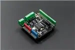
Arduino Motor Shield (L298N) (SKU:DRI0009)
Contents
1 Introduction
2 Specification
3 PinOut
4 Tutorial
4.1 Connection Diagram
4.2 Sample Code
4.2.1 PWM Speed Control
4.2.2 PLL Speed Control
5 Trouble shooting
Introduction
This motor shield allows Arduino to drive two channel DC motors. It uses a L298N chip which
deliveries output current up to 2A each channel. The speed control is achieved through conventional
PWM which can be obtained from Arduino’s PWM output Pin 5 and 6. The enable/disable function of
the motor control is signalled by Arduino Digital Pin 4 and 7.
The Motor shield can be powered directly from Arduino or from external power source. It is strongly
encouraged to use external power supply to power the motor shield.
�IOREF pin for Version 1.2:
The board's IOREF pin is connected with pin 5V! So when adding the DRI0009 to the
stack of board (controller), the controller's supply voltage would changed to 5V! So it
only can be compatible with the controller working at 5V. If you need to use controller
working at other voltage, e.g. 3.3V, you need CUT OFF the IOREF pin of DRI0009.
We are deeply sorry about the mistake! We will revise the design in the next version.
Specification
Logic Control Voltage:5V (From Arduino)
Motor Driven Voltage:4.8~35V (From Arduino or External Power Source)
Logic supply current Iss:≤36mA
Motor Driven current Io:≤2A
Maximum power consumption:25W(T=75 )
PWM、PLL Speed control mode
Control signal level:
High:2.3V≤Vin≤5V
Low:-0.3V≤Vin≤1.5V
PinOut
Control Mode Selection Jumpers:
The shield supports PWM and PLL(Phased Locked Loop) control Modes. The PWM mode uses
E1 and E2 to generate PWM signal. The PLL mode uses M1 and M2 to generate phase control
signal.
�Motor Terminal: Two DC motors are connected to blue motor terminals. The male header
behide the terminals are the same as the motor terminals.
PWRIN:
The motors can be powered by external power supply when the motor current exceeds the limits
provided from the Arduino. The swith between external and Arduino power is implemented by
two jumpers.
PWRIN: External Power
VIN: Arduino Power
�Control Signal Truth Table:
E1
M1
E2
M2
L
X
Motor 1 Disabled
L
X
Motor 2 Disabled
H
H
Motor 1 Backward
H
H
Motor 2 Backward
PWM
X
PWM Speed control
PWM
X
PWM Speed control
NOTE:
H is High level;
L is Low level;
PWM is Pulse Width Modulation signal;
X is any voltage level.
"PWM Mode"
Pin
Function
Digital 4
Motor 1 Direction control
Digital 5
Motor 1 PWM control
Digital 6
Motor 2 PWM control
Digital 7
Motor 2 Direction control
"PLL Mode"
Pin
Function
Digital 4
Motor 1 Enable control
Digital 5
Motor 1 Direction control
�Digital 6
Motor 2 Direction control
Digital 7
Motor 2 Enable control
Tutorial
Connection Diagram
Sample Code
PWM Speed Control
//Arduino PWM Speed Control:
int E1 = 5;
�int M1 = 4;
int E2 = 6;
int M2 = 7;
void setup()
{
pinMode(M1, OUTPUT);
pinMode(M2, OUTPUT);
}
void loop()
{
int value;
for(value = 0 ; value
很抱歉,暂时无法提供与“DRI0009”相匹配的价格&库存,您可以联系我们找货
免费人工找货- 国内价格 香港价格
- 1+122.551691+15.88715