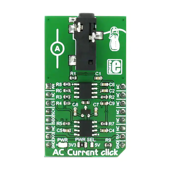
AC Current click
PID: MIKROE-2523
Weight: 27 g
AC Current click can measure alternating currents up to 30A and it features
the MCP3201 ADC (analog to digital) converter and the MCP607 CMOS Op Amp, both from
Microchip. The click is designed to run on either 3.3V or 5V power supply. It communicates
with the target MCU over an SPI interface, and the AN pin on the mikroBUS™ line.
AC Current click can only be used for sensors with voltage output (30A input current – 1V
output voltage amplitude). If someone wants to measure current with a sensor for a different
range (10A or 100A), then it is necessary to change the multiplication constant in firmware.
Note: This click board can be used for measuring current from a High-Voltage alternating
source, so it is important to know that there is danger from electric shock.
Note: AC Current click does not include the non-invasive AC current sensor. Take a look at the
AC Current click - bundle, if you want to buy both the sensor and the click.
�MCP3201 ADC converter
MCP3210 ADC converter is a 12-bit Analog-to-Digital converter. The device provides a single
pseudo-differential input.
The converter is capable of sample rates of up to 100 ksps at a clock rate of 1.6 MHz. The
MCP3201 device operates over a broad voltage range (2.7V-5.5V). Low-current design permits
operation with typical standby and active currents of only 500 nA and300 μA, respectively.
MCP607 CMOS Operational Amplifier
MCP607 operational amplifier is unity-gain stable with a low offset voltage (250 μV,
maximum). Performance characteristics include rail-to-rail output swing capability and low input
bias current (80 pA at +85°C, maximum).
Analog output
There is an Analog output for users who want to side step the onboard ADC and use an ADC
from a microcontroller instead.
One wire measurement
To measure current using this click it is necessary to put one wire through the sensor, not both.
How it works
When current flows through the sensor there is the same voltage waveform at the output of the
sensor (usually sinusoidal).
The first stage on the click board is the Low-Pass filter (whose role is the suppression of radio
waves and other noise from large cable from sensor to the click board). The R1 from the LowPass filter and the R2 make the voltage divider. After the Low-Pass filter there is the operational
amplifier, which is powered by single supply voltage. Because of the single supply this
operational amplifier can amplify only the positive part of signal (rectifier). Gain is defined by
the R4 and R3:
�The next stage is another Low-Pass filter which has to make continual DC voltage, which can be
used to calculate the input current.
The 12bit ADC is used to convert voltage to digital data. Development board MCU
communicates with the ADC using SPI and calculates RMS of input current.
Key features
3.5mm jack
Non‐invasive measurement
MCP3201 ADC converter
o 12‐bit resolution
o 100 ksps Maximum Sampling Rate at VDD = 5V
o 50 ksps Maximum Sampling Rate at VDD = 2.7V
o 500 nA Typical Standby Current, 2 μA Maximum
o 400 μA Maximum Active Current at 5V
MCP607 Op Amp
o Unity‐Gain Stable
o Low Input Offset Voltage: 250 μV (maximum)
o Low Input Bias Current: 80 pA (maximum at +85°C)
Interface: SPI
3.3V or 5V power supply
SPECIFICATION
Product Type
Applications
On-board
modules
Measurements
One phase measuring from the power line (110/220V) or some other alternating
voltage/current source, power consumption measurement, current monitoring
(over the analog output).
MCP3201, MCP607
Non-invasive measurement, 12-bit resolution MCP3201 ADC converter, the
click measures alternating currents up to 30A , MCP607 CMOS Op Amp
Key Benefits Non-invasive measurement
Interface
SPI
Power Supply 3.3V or 5V
Compatibility mikroBUS
Click board
M (42.9 x 25.4 mm)
size
Key Features
�
Pinout diagram
This table shows how the pinout on AC Current click corresponds to the pinout on the
mikroBUS™ socket (the latter shown in the two middle columns).
Notes
Pin
Pin
Notes
mikroBUStm
Analog AN 1 AN
PWM 16 NC Not connected
Not connected NC 2 RST
INT 15 NC Not connected
Chip select/Shutdown input CS 3 CS
TX 14 NC Not connected
SPI clock SCK 4 SCK
RX 13 NC Not connected
Serial data out MISO 5 MISO
SCL 12 NC Not connected
Not connected NC 6 MOSI
SDA 11 NC Not connected
Power supply +3.3V 7 3.3V
5V 10 +5V Power supply
Ground GND 8 GND
GND 9 GND Ground
Onboard jumpers
The table below shows information about onboard jumpers:
Designator Name
JP1
PWR.SEL.
Default
Position
Default
Option
Description
Left
3.3V
Power Supply Voltage Selection 3.3V/5V, left position
3.3V, right position 5V
�
Programming
This code snippet initializes MCU, AC Current click board and measures and shows current
value in mA.
01 void main()
02 {
03
system_init();
04
ac_current_init();
05
06
while ( true )
07
{
08
ac_current = 0;
09
ac_current = ac_current_get_mA();
10
usart_write();
11
Delay_ms( 1000 );
12
}
13 }
https://shop.mikroe.com/click/mixed-signal/ac-current 2/24/2017
�
很抱歉,暂时无法提供与“MIKROE-2523”相匹配的价格&库存,您可以联系我们找货
免费人工找货- 国内价格
- 1+135.77561
- 5+133.05760


 工商网监
湘ICP备2023018690号
工商网监
湘ICP备2023018690号