Page 1 of 2
PWM driver click
From MikroElektonika Documentation
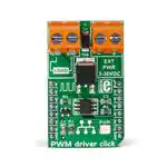
If you need to control DC motors with loads up to 10A, PWM driver click is the
perfect solution, thanks to the Silicon Lab Si8711CC one-channel isolator. It
communicates with the target MCU over PWM pin, and runs on a 5V power
supply. It can be used in a wide variety of ways, from controlling light intensity to
serving as an ON/OFF switch to control DC load circuits.
PWM driver click
Contents
◾ 1 Features and usage notes
◾ 1.1 MOSFET transistor
◾ 1.2 Onboard screw terminals
◾ 1.3 Key features
◾ 2 Pinout diagram
◾ 3 Additional information about the click
◾ 4 Programming
◾ 5 Resources
PWM driver click
Features and usage notes
IC/Module Si8711CC datasheet (http://www.silabs.com/Support%
20Documents/TechnicalDocs/Si87xx.pdf)
MOSFET transistor
The click contains a P-channel DMP3010LK3 MOSFET transistor. When the
click is used for PWM control it is not recommended to use it with loads of
wattage over 50W because the MOSFET chip can get overheated. However, this
does not apply when the click is used as an ON/OFF switch.
Onboard screw terminals
There are two pairs of screw terminals on the PWM driver click — one for the
external power supply and one for the DC load.
Interface
PWM
Power
5V
supply
Product
www.mikroe.com/click/pwm-driver
page
(http://www.mikroe.com/click/pwm-driver/)
Schematic PWM driver click schematic (http://cdndocs.mikroe.com/images/c/c2/PWM_driver_click_schematic_v100.pdf)
Key features
◾ Si8711CC isolator from Silicon Labs
◾ Data rates dc to 15 Mbps
◾ 1 channel diode emulator input
◾ PWM pin interface
◾ Two pairs of screw terminals
◾ 5V power supply
Pinout diagram
This table shows how the pinout on PWM driver click corresponds to the pinout on the mikroBUS™ socket (the latter shown in the two middle columns).
Notes
Pin
Pin
Notes
mikroBUStm
NC
1 AN
PWM 16 PWM PWM or GPIO (ON/OFF) when used as a switch
NC
2 RST
INT
NC
3 CS
TX
14 NC
NC
4 SCK
RX
13 NC
NC
5 MISO
SCL
12 NC
NC
6 MOSI
SDA 11 NC
This click runs on 5V power supply only NC
7 +3.3V
+5V
Ground
GND 8 GND
X
15 NC
10 +5V
Power supply
GND 9 GND Ground
�Page 2 of 2
Additional information about the click
There are two pairs of screw terminals on the PWM click. The table below shows their function.
Designator Name
Type (LED, BUTTON…) Description
LD1
LED
PWR
Power LED
CN1
EXTPWR CONNECTOR
External power supply connection
CN2
LOAD
Load connection
CONNECTOR
Programming
This demo demonstrates the change of light intensity of a halogen lamp; using the on-board potentiometer P1 (EasyPIC 7), you can regulate the light intensity.
For this demo we have used the EasyPIC v7 development system.
◾ Supply voltage within range of 3 – 30 V.
◾ Maximum output current detected: 15 mA.
◾ Wide operating temperature range: –40 to +125 °C
◾ Demo available for: ARM, PIC, PIC32, AVR and FTDI compilers.
This snippet shows the initialization of MCU (PWM and required port pins) and LCD. In an endless loop, we are reading current digitized value from ADC
channel 1 and showing it's value with light intensity. Also, luminosity percentage is given on the LCD.
1 void main()
2
{
3
MCU_Init();
// Configure PORTB pins as digital
4
Lcd_Init();
// Initialize Lcd
5
Lcd_Display();
// Display text
6
current_duty = 0;
7
PWM2_Start();
8
PWM2_Set_Duty(current_duty);
9
while ( 1 )
// Playing with Potentiometer P1 you can control current PWM duty cycle
10
// For visual result, look at LED PC1
11
{
12
uint8_t cur_duty_byte;
13
14
// Read 10 - bit ADC value and set newly acquired 8 - bit PWM duty
15
adc_rd = ADC_Read(1) & 0x0000FFFF;
16
current_duty = adc_rd / 4 ;
17
cur_duty_byte = LoWord(current_duty);
18
PWM2_Set_Duty(cur_duty_byte);
// Set newly acquired duty
19
cur_duty_byte = cur_duty_byte * 0.39; // 100 / 256
20
ByteToStr(cur_duty_byte, txt);
21
Lcd_Out(2, 11, txt);
22
Delay_ms( 20 );
23
}
24
}
25
Resources
◾
◾
◾
◾
PWM driver click schematic (http://cdn-docs.mikroe.com/images/c/c2/PWM_driver_click_schematic_v100.pdf)
Si8711CC datashet (http://www.silabs.com/Support%20Documents/TechnicalDocs/Si87xx.pdf)
MOSFET datasheet (http://www.diodes.com/_files/datasheets/DMP3010LK3.pdf)
mikroBUS™ standard specifications (http://download.mikroe.com/documents/standards/mikrobus/mikrobus-standard-specification-v200.pdf)
Retrieved from "http://docs.mikroe.com/index.php?title=PWM_driver_click&oldid=3136"
Category: Home page
◾ This page was last modified on 9 January 2017, at 14:09.
◾ Content is available under Creative Commons Attribution unless otherwise noted.
http://docs.mikroe.com/index.php?title=PWM_driver_click&printable=yes
1/20/2017
�
很抱歉,暂时无法提供与“MIKROE-2272”相匹配的价格&库存,您可以联系我们找货
免费人工找货- 国内价格
- 1+183.64802
- 5+179.97194
