AG931-07E
AAT003 40 KΩ Angle Sensor
Evaluation Kit
SN12447
NVE Corporation
(800) 467-7141
sensor-apps@nve.com
www.nve.com
�Kit Overview
Evaluation Kit Features
• AAT003-10E Angle Sensor
• Part # 12426 Split-Pole Alnico 5 Round Horseshoe Magnet
• Unity-Gain Buffer Amplifier
• 1.5 V to 5.5 V Power Supply
• Magnet Locating Fixture
AAT003-10E Features
• Tunneling Magnetoresistance (TMR) Technology
• Very High Output Signal Without Amplification
• Wide Airgap Tolerance
• 40 KΩ Nominal Bridge Resistance for Low Power
• Sine and Cosine Outputs for Direction Detection
• Ultraminiature TDFN6 Package
AAT-Series Sensor Applications
• Rotary Encoders
• Motor Shaft Position Sensors
• Battery-Powered Angle Sensors (AAT001-10E low-power version)
AAT003-10E Angle Sensor Description
The AAT003-10E angle sensor is a low power, high output magnetic sensor
element for position measurements when a rotating magnetic field is applied.
Sine and cosine signals are available for a quadrature output.
The sensor element has a resistance of approximately 40 KΩ, allowing a lownoise interface to signal-processing circuitry while still maintaining low power.
Outputs are proportional to the supply voltage and peak-to-peak output
voltages are much larger than conventional sensor technologies.
The part is packaged in NVE’s 2.5 mm x 2.5 mm x 0.8 mm TDFN6 surfacemount package
Visit www.nve.com for complete AAT003 product specifications.
�Quick Start
⇒ Connect VCC1 and VCC2 to a 5 V power supply.
⇒ Connect the “SIN” and “COS” screw terminals to an oscilloscope or to meters.
⇒ Place the split-pole magnet in the Plexiglas pocket SLOT DOWN.
⇒ Rotate the magnet.
VOLTAGE
⇒ The outputs should be similar to the following graph:
3
Sin
2.75
2.5
Cos
2.25
2
0
90
180
270
ROTATION
360
The output is insensitive to magnet spacing over a wide range. Signal is lost if
the magnet is too far away; if the magnet is too close the outputs will be nonsinusoidal. A relatively large magnet-sensor airgap is possible with the magnet
provided with the kit, although smaller magnets will require a smaller gap.
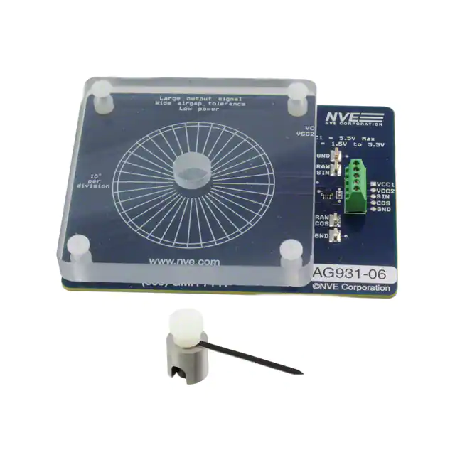
�Evaluation Board Layout
AAT003-10E
TMR angle sensor
100 nF
decoupling capacitor
Dual unity-gain
buffer amplifier
Large output signal
Wide airgap tolerance
Low power
5.5V max.
sensor supply input
VCC1 = 5.5V Max
VCC2 = 1.5V to 5.5V
Angular reticle
(10° per division)
1.5V to 5.5V
buffer amp
power supply input
GND
RAW
SIN
10°
per
division
FCVe
Pocket for
split-pole magnet
RAW
COS
VCC1
VCC2
SIN
COS
GND
GND
www.nve.com
(800) GMR-7141
Raw sensor
outputs
(unbuffered)
AG931-06
©NVE
Corporation
©
Cosine and
sine
buffered outputs
�Principles of Operation
Each of the four sensor elements contains two magnetic layers: a “pinned,” or
fixed direction layer; and a movable-direction, or “free” layer. Internal sensor
pairs are 90° out of phase to provide quadrature outputs.
The diagram below illustrates the configuration, using arrows to represent the
magnetic orientation of the layers:
Pinned Layer
Fr
ee
La
ye
r
Free layer aligns
with applied
magnetic field
Ap
pli
ed
(30 Ma
to gne
20 tic
0 O Fi
e) eld
Angle between
pinned and free
layers determines
sensor resistance
The sensor element free layers will align with the external field. As the applied
field changes direction, the angle between the free layer and the pinned layer
changes, changing the resistance of spintronic Tunneling Magnetoresistance
(TMR) elements, which changes the device output voltages.
In the typical configuration, an external magnet provides a saturating magnetic
field (30 to 200 Oe) in the plane of the sensor, as demonstrated in this kit.
Depending on the application, a bar magnet can also be used instead of a splitpole magnet.
�PCB Assembly
Raw output signals from the AAT003 are available as test points on the board.
The PCB assembly also includes a unity-gain buffer that provides lowimpedance outputs and buffers the sensor bridge from loading by downstream
electronics.
Ouput buffering may not be necessary in the end application depending on the
impedance of the connections to the outputs of the board.
AAT003-10E
1
Vcc
100 nF
R3 (Cosine)
6
Vcc
-
R2 (Sine)
5
Sin
2
Cos
1.5 V
to 5.5 V
R1 (Sine)
0V
to 5.5 V
+
VCC1
VCC2
SIN
COS
GND
Raw Sin
Raw Cos
GND
3
R4 (Cosine)
GND
4
+
TSV622
100
nF
AG931-07E Evaluation Kit schematic.
Separate power supply connections for the sensor and op amp (VCC1 and VCC2)
allow monitoring the current requirements of the sensor only. The minimum op
amp supply voltage is 1.5 V, while the AAT003 sensor has no minimum.
Sensitivity increases proportionately to the sensor supply voltage, as does
current consumption.
VCC1 and VCC2 can be connected together if desired.
�Limited Warranty and Liability
Information in this document is believed to be accurate and reliable. However, NVE does not give
any representations or warranties, expressed or implied, as to the accuracy or completeness of such
information and shall have no liability for the consequences of use of such information. In no event
shall NVE be liable for any indirect, incidental, punitive, special or consequential damages (including,
without limitation, lost profits, lost savings, business interruption, costs related to the removal or
replacement of any products or rework charges) whether or not such damages are based on tort
(including negligence), warranty, breach of contract or any other legal theory.
Right to Make Changes
NVE reserves the right to make changes to information published in this document including, without
limitation, specifications and product descriptions at any time and without notice.
Use in Life-Critical or Safety-Critical Applications
Unless NVE and a customer explicitly agree otherwise in writing, NVE products are not designed,
authorized or warranted to be suitable for use in life support, life-critical or safety-critical devices or
equipment. NVE accepts no liability for inclusion or use of NVE products in such applications and
such inclusion or use is at the customer’s own risk. Should the customer use NVE products for such
application whether authorized by NVE or not, the customer shall indemnify and hold NVE harmless
against all claims and damages.
Applications
Applications described in this document are illustrative only. NVE makes no representation or warranty
that such applications will be suitable for the specified use without further testing or modification.
Customers are responsible for the design and operation of their applications and products using NVE
products, and NVE accepts no liability for any assistance with applications or customer product design.
It is customer’s sole responsibility to determine whether the NVE product is suitable and fit for the
customer’s applications and products planned, as well as for the planned application and use of
customer’s third party customers. Customers should provide appropriate design and operating
safeguards to minimize the risks associated with their applications and products. NVE does not accept
any liability related to any default, damage, costs or problem which is based on any weakness or
default in the customer’s applications or products, or the application or use by customer’s third party
customers. The customer is responsible for all necessary testing for the customer’s applications and
products using NVE products in order to avoid a default of the applications and the products or of the
application or use by customer’s third party customers. NVE accepts no liability in this respect.
An ISO 9001 Certified Company
NVE Corporation
11409 Valley View Road
Eden Prairie, MN 55344-3617
©NVE Corporation
All rights are reserved. Reproduction in whole or in part is prohibited without the prior written
consent of the copyright owner.
Manual No.: SN12447
�
很抱歉,暂时无法提供与“AG931-07E”相匹配的价格&库存,您可以联系我们找货
免费人工找货