Additional Resources:
Product Page
date
03/25/2014
page
1 of 6
SERIES: AMT30 │ DESCRIPTION: MODULAR ENCODER
U
U, V, W commutation lines
small size 37 mm
line count up to 1024 PPR
optional line driver output (303LD)
single pulse index
capacitive ASIC technology
modular locking hub design for ease of installation
2, 4, 6, 8, 10, 12, or 20 pole motors
6 programmable functions
’One Touch’ commutation signal alignment
N
•
•
•
•
•
•
•
•
•
•
ED
FEATURES
ELECTRICAL
conditions/description
power supply
min
TI
parameter
4.5
current consumption
with unloaded outputs
U, V, W phase
commutation pole
2, 4, 6, 8, 10, 12, 20 (software programmable)
incremental output signals
A, B, Z (AMT303)
A, A, B, B, Z, Z (AMT303LD)
quadrature output square wave
quadrature output resolutions
96, 192, 200, 250, 384, 400, 500, 512, 800, 1000,
1024
index
one pulse per 360 deg.
position accuracy
parameter
5
5.5
V
8
10
mA
AMT303 (single ended) sink/source
AMT303LD (differential) sink/source
2
20
0.2
IS
C
MECHANICAL
conditions/description
min
typ
max. rotational speed
mounting options
mA
deg
max
units
8,000
RPM
±0.4
mm
max
units
125
°C
85
%
A) 2 x M1.6 on 16 mm (0.63”) bolt circle
B) 2 x #4 on 19.05 mm (0.75”) bolt circle
C) 2 x M1.6 or M2 on 20 mm (0.787”) bolt circle
D) 3 x M1.6 or M2 on 20.9 mm (0.823”) bolt circle
with washers in option B holes
E) 3 x M1.6 or M2 on 22 mm (0.866”) bolt circle
F) 4 x M1.6 or M2 on 25.4 mm (1”) bolt circle
axial play
D
units
PPR
O
incremental output waveform
quadrature output current
max
N
commutation output signals
typ
ENVIRONMENTAL
parameter
conditions/description
min
operating temperature
humidity
-40
non-condensing
vibration
10 ~ 500 Hz, 5 min. sweep, 2 hours each XYZ
shock
3 pulses, 6 ms, 3 each XYZ
cui.com
typ
5
G
200
G
�Additional Resources:
Product Page
CUI Inc │ SERIES: AMT30 │ DESCRIPTION: MODULAR ENCODER
date 03/25/2014 │ page 2 of 6
PART NUMBER KEY
ED
For customers that prefer a specific AMT303 configuration, please reference the custom configuration key below.
AMT303XX - XXXX - XXXX - XX - XX - X
Options:
“blank” = standard connector
C = locking connector
D = conformal coating with
standard connector
E = conformal coating with
locking connector
AMT303 KITS
N
Resolution (ppr):
0096
0500
0192
0512
0200
0800
0250
1000
0400
1024
Sleeve Bore Diameter:
2000 = 2 mm
3000 = 3 mm
3175 = 3.175 mm (1/8”)
4000 = 4 mm
4760 = 4.76 mm (3/16”)
5000 = 5 mm
6000 = 6 mm
6350 = 6.35 mm (1/4”)
8000 = 8 mm
SKIT = 8 sleve kit
Motor Poles:
02
10
04
12
06
20
08
Direction:
“blank” = CCW
CW = clockwise
TI
Output Signals:
“blank” = A, B, Z, U, V, W
LD = Line Driver
A, A, B, B, Z, Z, U, V, W
U
Base Number
IS
C
O
N
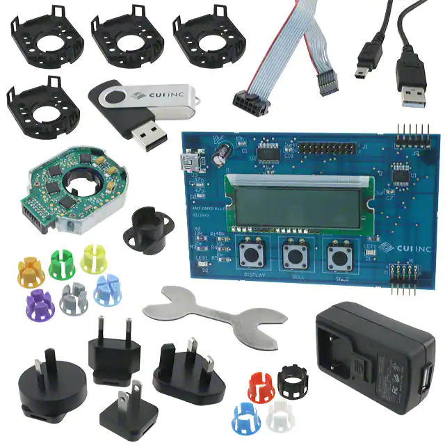
In order to provide maximum flexibility for our customers, the AMT303 series is provided in kit form standard. This allows the user to implement the encoder
into a range of applications using one sku#, reducing engineering and inventory costs.
SLEEVES
8mm
1/4 inch
(6.35mm)
6mm
5mm
3/16 inch
(4.76mm)
4mm
1/8 inch
(3.175mm)
3mm
2mm
Blue
Snow
Red1
Green1
Yellow1
Gray60
Purple1
Orange
Light Sky Blue
ORDERING GUIDE
AMT303XX-V
TOOL A
BASE
TOP COVER
D
Output Signals:
“blank” = A, B, Z, U, V, W signals
LD = Line Driver
A, A, B, B, Z, Z, U, V, W signals
cui.com
TOOL C
SHAFT
ADAPTER
�Additional Resources:
Product Page
CUI Inc │ SERIES: AMT30 │ DESCRIPTION: MODULAR ENCODER
date 03/25/2014 │ page 3 of 6
ENCODER INTERFACE
PINOUT CONNECTOR 1
AMT303LD
GND_C1
GND_C1
13
N/A
-Z
12
Z
Z
11
N/A
-A
10
A
A
9
N/A
-B
8
B
B
7
V
V
6
5 V+
5 V+
5
W
W
4
GND
GND
3
U
U
2
zero set
zero set
1
N/A
N/A
N
AMT303
TI
#
U
Function
14
Locking Connector Option
ED
Standard Connector Option
B
N
Notes:
1. GND_C is mode selection line used at
startup to determine encoder mode:
VCC/Floating: SPI Communication Mode
Ground: Normal Operation Mode
Standard use requires attaching GND_C
Pin# 14 to GND in order to get Commutation output.
SPI Communication mode allows the user to write
parameters to the encoder via SPI link, contact CUI
Inc. for more details.
7
5
3
1
14 12 10 8
6
4
2
O
13 11 9
IS
C
Mating Connector:
Samtec ISDF-07-D
DETAIL B
SCALE 4 : 1
13 11 9
Mating Connector:
Samtec ISDF-07-D-L
D
7
5
3
1
14 12 10 8
6
4
2
DETAIL B
SCALE 4 : 1
Demo Board Side
Encoder Side
Samtec
ISDF-07-D
B
1' 0.25"
(304.8)
Demo Board Cable
(Cable available without Demo Board Connector)
cui.com
28 AWG
10 conductor
1.27 mm pitch
�Additional Resources:
Product Page
CUI Inc │ SERIES: AMT30 │ DESCRIPTION: MODULAR ENCODER
date 03/25/2014 │ page 4 of 6
MECHANICAL DRAWING
R15.49 0.610
15.30 0.602
15.33 0.604
N
U
37.39 1.472
ED
10.34 0.407
28.58 1.125
TI
10.93 0.430
A (3 PLCS)
22.00 0.866
0.55
19.05 0.750
2.95 0.116
(2 PLCS)
TOLERANCE:
±0.05mm UNLESS OTHERWISE
SPECIFIED
1.70 0.067
(2 PLCS)
O
R2.10 0.083
12.60 0.496
N
21.45 0.844
2.00 0.079
(4 PLCS)
20.90 0.823
IS
C
DETAIL A
SCALE 4 : 1
25.48 1.003
16.00 0.630
18.60mm
5.30mm
5.30mm
D
18.60mm
AMT303 COMM WWYY
US Patent No. 6892590
AMT303LD COMM WWYY
US Patent No. 6892590
R1.20mm
R1.20mm
SCALE 5:1
SCALE 5:1
cui.com
�Additional Resources: Product Page
CUI Inc │ SERIES: AMT30 │ DESCRIPTION: MODULAR ENCODER
date 03/25/2014 │ page 5 of 6
ENCODER OPERATIONAL MODE
Initialization mode:
ED
– At power up the encoder goes through an initiation and stabilization procedure. This includes
microprocessor stabilization and the program for combining Coarse and Fine channel of the encoder for
getting the absolute start position. This takes less than 0.1 seconds.
Tracking mode:
U
– MCU 12 bit position register is updated from Fine Asic every 48 μs.
– The commutation program in the MCU has a compensation for the average delay caused by the update
rate, leaving a remaining jitter of less than 24 μs RMS.
•The communication jitter expressed in electrical degrees will be proportional speed and
does not reach 6 deg RMS until the speed reaches the following values:
Commuta�on Ji�er in Electrical Degrees
N
12
10
TI
8
6
4
2
0
0
N
Ji�er (Electrical Degrees)
14
2000
4000
6000
8000
4 pole
6 pole
8 pole
10 pole
12 pole
20 pole
10000
O
RPM
COMMUTATION ALIGNMENT AND SETTING THE ZERO POINT
IS
C
We strongly recommend the use of the AMT303 series demo board to set commutation zero. It greatly
simplifies and expedites the process. The demo board also allows setting of resolution, # of motor poles,
direction of quadrature increment, and commutation angle offset (when required). If you do not have or
cannot obtain a demo board, use the following procedure to align the AMT303XX commutation angle with your
motor:
Mount the AMT303 series encoder to the motor.
2.
Put the motor in a ‘locked rotor’ condition. Consult your motor manufacturer if you are not certain how to lock the
rotor for commutation alignment.
3.
With the motor in a locked rotor position, pull pin# 2 (zero set) low, tie Pin 2 to Ground, to write the rotor position
into non-volatile memory in the encoder.
4.
Power cycle the encoder, i.e., remove power from it. The commutation position is now permanently aligned with
the motor rotor zero position and will use this offset at initialization every time at startup.
Note: The procedure is based on the standard “WYE” motor phase connection configuration. If your motor uses
other than the “WYE” phase connection, you must acquire the AMT303 series demo board to program the
required offset to align encoder commutation signal zero with motor zero position.
D
1.
cui.com
�Additional Resources:
Product Page
CUI Inc │ SERIES: AMT30 │ DESCRIPTION: MODULAR ENCODER
date 03/25/2014 │ page 6 of 6
REVISION HISTORY
rev.
description
date
05/04/2011
initial release
updated electrical specifications
1.02
updated pin-out and speed specification
1.03
addition of commutation jitter, shock, speed, and position accuracy,
updated part number key
09/30/2011
1.04
updated Part Number Key
03/09/2012
1.05
clarification notes
1.06
added locking connector drawing
1.07
updated spec
1.08
added axial play specification
ED
1.0
1.01
06/10/2011
09/21/2011
08/17/2012
U
03/29/2013
01/30/2014
03/25/2014
D
IS
C
O
N
TI
N
The revision history provided is for informational purposes only and is believed to be accurate.
Headquarters
20050 SW 112th Ave.
Tualatin, OR 97062
800.275.4899
Fax 503.612.2383
cui.com
techsupport@cui.com
CUI offers a one (1) year limited warranty. Complete warranty information is listed on our website.
CUI reserves the right to make changes to the product at any time without notice. Information provided by CUI is believed to be accurate and reliable. However, no responsibility is
assumed by CUI for its use, nor for any infringements of patents or other rights of third parties which may result from its use.
CUI products are not authorized or warranted for use as critical components in equipment that requires an extremely high level of reliability. A critical component is any component of a
life support device or system whose failure to perform can be reasonably expected to cause the failure of the life support device or system, or to affect its safety or effectiveness.
�


 工商网监
湘ICP备2023018690号
工商网监
湘ICP备2023018690号
