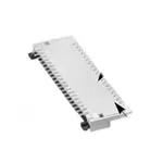
0.3mm Contact Pitch, 1.25mm above the board, Flexible Printed Circuit Connectors
FH 23 Series
●Staggered termination configuration. Only 1.25 mm
above the board.
Leadless type
Jun.1.2020 Copyright 2020 HIROSE ELECTRIC CO., LTD. All Rights Reserved.
Completely enclosed
bottom surface
Lead type
1.25mm
■Features
1. FPC low insertion force and high holding force
Hirose Electric's unique low insertion force (LIF) design
(patents pending) improves the Flexible Printed Circuit
(FPC) holding force after insertion.
2. Temporary hold of FPC
There is no need to hold the FPC after insertion in the
connector. The connector will hold it in correct position,
allowing closing of the actuator.
3. Easy board mounting
The surface mounted termination of the contacts is staggered
on 0.6 mm centers, positioned on front and back of the
connector.
Bottom of the connector is completely insulated,
allowing conductive traces on PCB to run under the
connector.
When the actuator is opened
4. Proven Flip-lock Actuator assures easy
and reliable operation
Rotating actuator permits easy insertion and reliable
connection with the FPC. Tactile sensation confirms complete
mechanical locking of the actuator and the electrical
connection.
5. Variations to suit different mounting areas
Available with lead and leadless type of terminations
(for opposing FPC insertion side).
6. Designed for placement with automatic
equipment
Temporary hold of FPC
Flat top surface allows pick-up with vacuum nozzles.
Packaged in embossed tape, on reel. One reel contains 2,500
pieces.
7. Accepts 0.2mm thick FPC
8. Variety of contact positions
Available with 15,17,21,23,25,27,31,33,37,39,45,51,61and 71
pos.
9. Halogen Free
The connector does not use chlorine and bromine
exceeding standard limits.
*Defined in accordance with IEC61249-2-21
*Br 900ppm or lower, Cl 900ppm or lower, Br + Cl 1,500ppm or
lower
When the actuator is closed
2013.11w
1
�FH23 Series●0.3mm Contact Pitch, 1.25mm above the board, Flexible Printed Circuit Connectors
■Product Specifications
Operating temperature range
-55 ç to +85ç (Note 1)
Operating humidity range
30V AC
Relative humidity 90% max. (No condensation)
Current rating
0.3A
Ratings
Voltage rating
Recommended FPC
Thickness: = 0.2±0.03mm Gold plated
Item
Specification
Conditions
1. Insulation resistance 50 M ohms min.
2. Withstanding voltage No flashover or insulation breakdown
3. Contact resistance
100 m ohms max.
*Including FPC/FFC conductor resistance
Contact resistance: 100 m ohms max.
4. Durability
4. (insertion / withdrawal) No damage, cracks, or parts dislocation.
Jun.1.2020 Copyright 2020 HIROSE ELECTRIC CO., LTD. All Rights Reserved.
Storage temperature range
-10ç to +50ç (Note 2)
Storage humidity range
Relative humidity 90% max. (No condensation)
100 V DC
90 V AC/one minute
1 mA AC
10 cycles
5. Vibration
No electrical discontinuity of 1 μs or more.
Contact resistance: 100 m ohms max.
No damage, cracks, or parts dislocation.
Frequency: 10 to 55 Hz, single amplitude of 0.75 mm, 10
cycles, 3 axis.
6. Shock
No electrical discontinuity of 1 μs or more.
Contact resistance: 100 m ohms max.
No damage, cracks, or parts dislocation.
Acceleration of 981 m/s 2 , 6ms duration, sine half-wave
waveform, 3 cycles, 3 axis.
7. Humidity
(Steady state)
Contact resistance: 100 m ohms max.
Insulation resistance: 50 M ohms min.
No damage, cracks, or parts dislocation.
96 hours at 40°C and humidity of 90% to 95%
8. Temperature cycle
Contact resistance: 100 m ohms max.
Insulation resistance: 50 M ohms min.
No damage, cracks, or parts dislocation.
Temperature:-55ç/+15ç to +35ç/+85ç/+15ç to +35ç
Time: 30/ 2 to 3 / 30 / 2 to 3 (Minutes)
5 cycles
9. Resistance to
soldering heat
No deformation of
components affecting performance.
Reflow: At the recommended temperature profile
Manual soldering: 350 ç±5 ç for 5 seconds
Note 1: Includes temperature rise caused by current flow.
Note 2: The term ”storage” refers to products stored for long period of time prior to mounting and use. Operating
Temperature Range and Humidity range covers non-conducting condition of installed connectors in storage,
shipment or during transportation.
■Materials
Part
Material
Finish
Insulator
LCP
Color: Beige
Actuator
LCP
Color: Black
Contacts
Phosphor bronze
Gold plated
Remarks
UL94V-0
---------------
■Ordering information
FH 23 - 39S - 0.3 SHW (05)
1
2
3
1 Series name : FH
2 Series No : 23
3 Number of contacts : 15 to 71
4 Contact pitch: 0.3mm
5 Terminal type
SHW: SMT horizontal mounting type, lead type termination.
SHAW: SMT horizontal mounting type, lead-less type termination.
2
4
5
6
6 Plating specifications :
(05) : Gold plated (All contact positions except 51
contacts)
(06) : Gold plated (51 contacts)
�FH23 Series●0.3mm Contact Pitch, 1.25mm above the board, Flexible Printed Circuit Connectors
■Connector Dimensions (Lead Type termination)
A
0.3
B
1.7
(0.15)
1.25(Including contact terminal leads)
2.45
0.6
0.6
Number of contacts indicator
(0.12)
C
(2.84)
Jun.1.2020 Copyright 2020 HIROSE ELECTRIC CO., LTD. All Rights Reserved.
**
0.05MAX.
0.05MAX.
E
0.1MAX.
0.55
(D: FPC insertion area dimensions)
1
4.15
0.5
0.1MAX.
2
1
2
Notes 1 The coplanarity of each terminal lead is within 0.1.
2 The contact terminal lead position indicates the dimension from the E surface, the bottom surface of the insulator body.
3 Any discoloration of the plastic compound will NOT AFFECT form, fit or function of the connector.
4 Packaged on tape and reel only. Check packaging specification.
Lead Type
Unit: mm
Part Number
CL No.
Number of Contacts
A
B
C
D
FH23-15S-0.3SHW(05)
586-1317-0-05
FH23-17S-0.3SHW(05)
586-1300-7-05
15
7
3.6
4.2
4.83
17
7.6
4.2
4.8
5.43
FH23-21S-0.3SHW(05)
FH23-23S-0.3SHW(05)
586-1314-1-05
21
8.8
5.4
6
6.63
586-1324-5-05
23
9.4
6
6.6
7.23
FH23-25S-0.3SHW(05)
586-1322-0-05
25
10
6.6
7.2
7.83
FH23-27S-0.3SHW(05)
586-1308-9-05
27
10.6
7.2
7.8
8.43
FH23-31S-0.3SHW(05)
586-1302-2-05
31
11.8
8.4
9
9.63
FH23-33S-0.3SHW(05)
586-1304-8-05
33
12.4
9
9.6
10.23
FH23-37S-0.3SHW(05)
586-1335-1-05
37
13.6
10.2
10.8
11.43
FH23-39S-0.3SHW(05)
586-1306-3-05
39
14.2
10.8
11.4
12.03
FH23-45S-0.3SHW(05)
586-1318-2-05
45
16
12.6
13.2
13.83
FH23-51S-0.3SHW(06)
586-1312-6-06
51
17.8
14.4
15
15.63
FH23-61S-0.3SHW(05)
586-1310-0-05
61
20.8
17.4
18
18.63
FH23-71S-0.3SHW(05)
586-1320-4-05
71
23.8
20.4
21
21.63
Note1: Embossed tape reel packaging(2,500 pieces/reel)
Order by number of reels.
Note2: The specification of (06) is applied to number of 51.
Refer to ordering information.
3
�FH23 Series●0.3mm Contact Pitch, 1.25mm above the board, Flexible Printed Circuit Connectors
■Connector Dimensions Diagram (Leadless Type termination)
A
0.3
1.7
B
(0.15)
1.25 (Including contact terminal leads)
2.45
0.6
Jun.1.2020 Copyright 2020 HIROSE ELECTRIC CO., LTD. All Rights Reserved.
**
0.6
Number of contacts indicator
(0.12)
(2.84)
C
0.05MAX.
0.1MAX.
(D: FPC insertion area dimensions)
1
0.05MAX.
E
0.55
0.1MAX.
4.15
2
1
2
Notes 1 The coplanarity of each terminal lead is within 0.1.
2 The contact terminal lead position indicates the dimension from the E surface, the bottom surface of the insulator body.
3 Any discoloration of the plastic compound will NOT AFFECT form, fit or function of the connector.
4 Packaged on tape and reel only. Check packaging specification.
Leadless Type
Part Number
Unit: mm
CL No.
Number of Contacts
A
B
C
D
FH23-15S-0.3SHAW(05)
586-1316-7-05
FH23-17S-0.3SHAW(05)
586-1301-0-05
15
7
3.6
4.2
4.83
17
7.6
4.2
4.8
5.43
FH23-21S-0.3SHAW(05)
FH23-23S-0.3SHAW(05)
586-1315-4-05
21
8.8
5.4
6
6.63
586-1325-8-05
23
9.4
6
6.6
7.23
FH23-25S-0.3SHAW(05)
586-1323-2-05
25
10
6.6
7.2
7.83
FH23-27S-0.3SHAW(05)
586-1309-1-05
27
10.6
7.2
7.8
8.43
FH23-31S-0.3SHAW(05)
586-1303-5-05
31
11.8
8.4
9
9.63
FH23-33S-0.3SHAW(05)
586-1305-0-05
33
12.4
9
9.6
10.23
FH23-39S-0.3SHAW(05)
586-1307-6-05
39
14.2
10.8
11.4
12.03
FH23-45S-0.3SHAW(05)
586-1319-5-05
45
16
12.6
13.2
13.83
FH23-51S-0.3SHAW(06)
586-1313-9-06
51
17.8
14.4
15
15.63
FH23-61S-0.3SHAW(05)
586-1311-3-05
61
20.8
17.4
18
18.63
FH23-71S-0.3SHAW(05)
586-1321-7-05
71
23.8
20.4
21
21.63
Note1: Embossed tape reel packaging(2,500 pieces/reel)
Order by number of reels.
Note2: The specification of (06) is applied to number of 51.
Refer to ordering information.
4
�FH23 Series●0.3mm Contact Pitch, 1.25mm above the board, Flexible Printed Circuit Connectors
■Recommended PCB Land and Metal Mask Dimensions (Lead Type)
(5.2)
3.45±0.05
(0.1)
0.3±0.05 (Land)
0.25±0.05 (Metal mask)
0.3±0.05
1.25±0.05
(5.4)
0.7±0.05
B±0.05
0.6±0.05
0.25±0.05 (Metal mask)
C±0.05
Lead Type
Unit: mm
Number of Contacts
B
FH23-15S-0.3SHW(05) 586-1317-0-05
Part Number
CL No.
15
3.6 4.2 4.8
FH23-33S-0.3SHW(05) 586-1304-8-05
33
9
FH23-17S-0.3SHW(05) 586-1300-7-05
17
4.2 4.8 5.4
FH23-37S-0.3SHW(05) 586-1335-1-05
37
10.2 10.8 11.4
FH23-21S-0.3SHW(05) 586-1314-1-05
21
5.4
6.6
FH23-39S-0.3SHW(05) 586-1306-3-05
39
10.8 11.4 12
FH23-23S-0.3SHW(05) 586-1324-5-05
23
6.6 7.2
FH23-45S-0.3SHW(05) 586-1318-2-05
45
12.6 13.2 13.8
FH23-25S-0.3SHW(05) 586-1322-0-05
25
6.6 7.2 7.8
FH23-51S-0.3SHW(06) 586-1312-6-06
51
14.4 15 15.6
FH23-27S-0.3SHW(05) 586-1308-9-05
27
7.2 7.8 8.4
FH23-61S-0.3SHW(05) 586-1310-0-05
61
17.4 18 18.6
FH23-31S-0.3SHW(05) 586-1302-2-05
31
8.4
FH23-71S-0.3SHW(05) 586-1320-4-05
71
20.4 21 21.6
Number of Contacts
B
6
C
6
9
G
9.6
Part Number
CL No.
C
G
9.6 10.2
■Recommended Land and Metal Mask Dimensions (Leadless Type)
( 0.1 )
0.3±0.05(Land)
0.6±0.05
0.25±0.05(Metal mask)
(4.6)
0.3±0.05
1.25±0.05
2.9±0.05
0.65±0.05
B±0.05
(4.8)
Recommended metal mask thickness: t = 0.1 mm
0.3±0.05(Land)
0.6±0.05
(0.1)
Jun.1.2020 Copyright 2020 HIROSE ELECTRIC CO., LTD. All Rights Reserved.
0.3±0.05 (Land)
(0.1)
Recommended metal mask thickness: t = 0.1 mm
0.6±0.05
0.25±0.05(Metal mask)
C±0.05
Leadless Type
Part Number
Unit: mm
CL No.
Number of Contacts
B
C
G
Part Number
CL No.
Number of Contacts
B
9
C
G
FH23-15S-0.3SHAW(05) 586-1316-7-05
15
3.6 4.2 4.8
FH23-33S-0.3SHAW(05) 586-1305-0-05
33
FH23-17S-0.3SHAW(05) 586-1301-0-05
17
4.2 4.8 5.4
FH23-39S-0.3SHAW(05) 586-1307-6-05
39
10.8 11.4 12
FH23-21S-0.3SHAW(05) 586-1315-4-05
21
5.4
6.6
FH23-45S-0.3SHAW(05) 586-1319-5-05
45
12.6 13.2 13.8
FH23-23S-0.3SHAW(05) 586-1325-8-05
23
6.6 7.2
FH23-51S-0.3SHAW(06) 586-1313-9-06
51
14.4 15 15.6
FH23-25S-0.3SHAW(05) 586-1323-2-05
25
6.6 7.2 7.8
FH23-61S-0.3SHAW(05) 586-1311-3-05
61
17.4 18 18.6
FH23-27S-0.3SHAW(05) 586-1309-1-05
27
7.2 7.8 8.4
FH23-71S-0.3SHAW(05) 586-1321-7-05
71
20.4 21 21.6
FH23-31S-0.3SHAW(05) 586-1303-5-05
31
8.4
6
6
9
9.6 10.2
9.6
5
�FH23 Series●0.3mm Contact Pitch, 1.25mm above the board, Flexible Printed Circuit Connectors
■Recommended FPC Dimensions
G±0.05
C±0.03
0.3±0.07
1
0.3 +0.04
-0.03
( 0.1 )
0.2±0.03
(0.07)
stiffener
(0.5)
(0.2)
Jun.1.2020 Copyright 2020 HIROSE ELECTRIC CO., LTD. All Rights Reserved.
+0.04
-0.03
(2)
1.1 ±0.15
0.3 ±0.15
( 0.2 )
0.4
2.8 ±0.15
3.5 ±0.3
(Area with removed covering layer film)
1.3 ±0.15
0.6 ±0.02
2R0
.2
0.3 ±0.07
(0.05)
(0.1 between conductors)
(0.2 conductor width)
B±0.03
0.6±0.07
2
0.3±0.02
T
0.6±0.02
6
+0.04
- 0.03
1
0.3
2
Dimension T must be 0.5mm minimum.
also permitted when drawing plated leads.
�FH23 Series●0.3mm Contact Pitch, 1.25mm above the board, Flexible Printed Circuit Connectors
■FH23 Series FPC Construction (Recommended Specifications)
1. Using Single-sided FPC
Material Name
Covering film layer.
Material
Polyimide
1 mil thick.
Jun.1.2020 Copyright 2020 HIROSE ELECTRIC CO., LTD. All Rights Reserved.
Cover adhesive
Thickness (μm)
(25)
(25)
Surface treatment
Nickel under plated 1 to 5μm /
Gold plated 0.2μm
Copper foil
Cu
Base adhesive
Heat-hardened adhesive
25
Base film
Polyimide
1 mil thick
25
Reinforcement material adhesive Heat-hardened adhesive
30
Stiffener
1oz
Polyimide
3 mil thick
Total
3
35
75
193
2. Using Double-sided FPC
Material
Material Name
Covering layer film
Polyimide
1 mil thick
Thickness (μm)
(25)
(25)
Cover adhesive
Surface treatment
Nickel under plated 1 to 5μm /
Gold plated 0.2μm
Through-hole copper
Cu
Copper foil
Cu
Base adhesive
Heat-hardened adhesive
18
Base film
Polyimide
1 mil thick
25
Base adhesive
Heat-hardened adhesive
18
Copper foil
Cu
Cover adhesive
Heat-hardened adhesive
25
Covering layer film
Polyimide
1 mil thick
25
Reinforcement material adhesive Heat-hardened adhesive
25
Stiffener
Polyimide
3
15
1/2oz
1/2oz
1 mil thick
Total
18
(18)
25
197
Note : Recommended specification for FPC 0.2±0.03 mm thick.
3. Precautions
1. This specification is a recommendation for the construction of the FH23 Series FPC (t=0.2±0.03).
2. For details about the construction, please contact the FPC manufacturers.
7
�FH23 Series●0.3mm Contact Pitch, 1.25mm above the board, Flexible Printed Circuit Connectors
■Packaging Specification
●Embossed Carrier Tape Dimensions
●Embossed Carrier Tape Dimensions
(5.1)
(0.5)
Ø1.
5
Flat surface for placement
with Automatic equipment
(2.45)
1.5 +0.1
0
Unreeling direction
Jun.1.2020 Copyright 2020 HIROSE ELECTRIC CO., LTD. All Rights Reserved.
(1.7)
(0.3)
(0.85)
(5.1)
Unreeling direction
H±0.3
J±0.1
(L)
Flat surface for placement
with Automatic equipment
(Ø1
3)
●Reel Dimensions
(0.5)
(2.45)
(M)
K±0.1
(0.3)
(N)
K±0.1
(L)
2±0.15 12±0.1
(1.7)
1.7 +0.15
0
(0.85)
(M)
(N)
Ø1
.5
+
0
0 .1
12±0.1
H±0.3
2±0.15
1.75±0.1
4±0.1
4±0.1
1.75±0.1
(Tape width of 32 mm min.)
+0
.1
0
(Tape width of 24 mm max.)
(Ø80)
(Ø380)
(Q : INSIDE)
(R : OUTSIDE)
Leader (400 mm min.)
Section with connectors
Trailer
Embossed carrier tape
10 Empty components min.
Part Number
CL No.
Number of Contacts
H
586-1317-0-05
586-1300-7-05
586-1314-1-05
586-1324-5-05
586-1322-0-05
586-1308-9-05
586-1302-2-05
586-1304-8-05
586-1335-1-05
586-1306-3-05
586-1318-2-05
586-1312-6-06
586-1310-0-05
586-1320-4-05
15
17
21
23
25
27
31
33
37
39
45
51
61
71
16
16
16
24
24
24
24
24
24
24
24
32
32
44
Part Number
CL No.
Number of Contacts
H
FH23-15S-0.3SHAW(05)
FH23-17S-0.3SHAW(05)
FH23-21S-0.3SHAW(05)
FH23-23S-0.3SHAW(05)
FH23-25S-0.3SHAW(05)
FH23-27S-0.3SHAW(05)
FH23-31S-0.3SHAW(05)
FH23-33S-0.3SHAW(05)
FH23-39S-0.3SHAW(05)
FH23-45S-0.3SHAW(05)
FH23-51S-0.3SHAW(06)
FH23-61S-0.3SHAW(05)
FH23-71S-0.3SHAW(05)
586-1316-7-05
586-1301-0-05
586-1315-4-05
586-1325-8-05
586-1323-2-05
586-1309-1-05
586-1303-5-05
586-1305-0-05
586-1307-6-05
586-1319-5-05
586-1313-9-06
586-1311-3-05
586-1321-7-05
15
17
21
23
25
27
31
33
39
45
51
61
71
16
16
16
24
24
24
24
24
24
24
32
32
44
FH23-15S-0.3SHW(05)
FH23-17S-0.3SHW(05)
FH23-21S-0.3SHW(05)
FH23-23S-0.3SHW(05)
FH23-25S-0.3SHW(05)
FH23-27S-0.3SHW(05)
FH23-31S-0.3SHW(05)
FH23-33S-0.3SHW(05)
FH23-37S-0.3SHW(05)
FH23-39S-0.3SHW(05)
FH23-45S-0.3SHW(05)
FH23-51S-0.3SHW(06)
FH23-61S-0.3SHW(05)
FH23-71S-0.3SHW(05)
8
Top cover tape
10 Empty components min.
J
-----------28.4
28.4
40.4
J
----------28.4
28.4
40.4
K
L
M
N
Q
Unit: mm
R
7.5
7.5
7.5
11.5
11.5
11.5
11.5
11.5
11.5
11.5
11.5
14.2
14.2
20.2
7.3
7.9
9.1
9.7
10.3
10.9
12.1
12.7
13.9
14.5
16.3
18.1
21.1
24.1
5.1
5.7
6.9
7.5
8.1
8.7
9.9
10.5
11.7
12.3
14.1
15.9
18.9
21.9
4.5
5.1
6.3
6.9
7.5
8.1
9.3
9.9
11.1
11.7
13.5
15.3
18.3
21.3
17.4
17.4
17.4
25.4
25.4
25.4
25.4
25.4
25.4
25.4
25.4
33.4
33.4
45.4
21.4
21.4
21.4
29.4
29.4
29.4
29.4
29.4
29.4
29.4
29.4
37.4
37.4
49.4
K
L
M
N
Q
R
7.5
7.5
7.5
11.5
11.5
11.5
11.5
11.5
11.5
11.5
14.2
14.2
20.2
7.3
7.9
9.1
9.7
10.3
10.9
12.1
12.7
14.5
16.3
18.1
21.1
24.1
5.1
5.7
6.9
7.5
8.1
8.7
9.9
10.5
12.3
14.1
15.9
18.9
21.9
4.5
5.1
6.3
6.9
7.5
8.1
9.3
9.9
11.7
13.5
15.3
18.3
21.3
17.4
17.4
17.4
25.4
25.4
25.4
25.4
25.4
25.4
25.4
33.4
33.4
45.4
21.4
21.4
21.4
29.4
29.4
29.4
29.4
29.4
29.4
29.4
37.4
37.4
49.4
�FH23 Series●0.3mm Contact Pitch, 1.25mm above the board, Flexible Printed Circuit Connectors
■Recommended Temperature Profile
Max. 250ç
250
HRS test condition
Solder method
Environment
Solder composition
Temperature
230ç
200
200ç
Test board
150
150ç
Land dimensions
(ç)
100
Jun.1.2020 Copyright 2020 HIROSE ELECTRIC CO., LTD. All Rights Reserved.
Metal mask
50
25ç (60 sec.) 90 sec. to 120 sec.
(60 sec.)
0
Start
Preheating
Time (Seconds)
Soldering
:Reflow, IR/hot air
:Room air
:Paste, 96.5%Sn/3.0%Ag/0.5%Cu
(Senju Metal Industry, Co., Ltd.’s
Part Number: M705-221-CM5-3210.5)
:Glass epoxy 45mm∞100mm∞1.6mm
thick
: Lead type
0.3mm∞1.25mm,
0.3mm∞0.7mm
Leadless type 0.3mm∞1.25mm,
0.3mm∞0.65mm
: Lead type
0.25mm∞1.25mm∞0.1mm thick
0.25mm∞0.7mm∞0.1mm thick
Leadless type
0.25mm∞1.25mm∞0.1mm thick
0.25mm∞0.65mm∞0.1mm thick
In individual applications the actual temperature may vary,
depending on solder paste type, volume/thickness and
board size/thickness. Consult tour solder paste and
equipment manufacturer for specific recommendations.
9
�FH23 Series●0.3mm Contact Pitch, 1.25mm above the board, Flexible Printed Circuit Connectors
■Connector Operating Instructions, precautions and recommendations
Operation
1.FPC Termination procedure.
Connector installed on the board.
1) Lift up the actuator. Use thumb or index finger.
Jun.1.2020 Copyright 2020 HIROSE ELECTRIC CO., LTD. All Rights Reserved.
2) Fully insert the FPC in the connector parallel to mounting surface, with the exposed conductive traces
facing down.
FPC conductor surface
(Bottom side)
photo 1
3) Rotate down the actuator until firmly closed.
NOTE: The FPC must be fully inserted in the connector. If not fully inserted, the actuator will not
close properly. Should this be the case, lift up the
actuator (per Step 2 below) and repeat the process
(starting with Step 1 above)
4) For connectors with multiple contacts, such as 61
and 71 pos. rotate down the actuator pushing at
both ends.
2.FPC Removal
1) Lift up the actuator.
2) Carefully remove the FPC.
10
photo 2
photo 3
�FH23 Series●0.3mm Contact Pitch, 1.25mm above the board, Flexible Printed Circuit Connectors
■Connector Operating Instructions, precautions and recommendations
Precautions
Jun.1.2020 Copyright 2020 HIROSE ELECTRIC CO., LTD. All Rights Reserved.
1) Do not apply excessive force or use any type of tool to operate the actuator.
2) The connector will assure reliable performance when the actuator is open to 90° maximum Do not exceed this angle, as this
may cause permanent damage to the connector.
3) Properly insert the FPC at the positioning part of the connector.
Locking the FPC while it is partially inserted, may cause lock
damage, disconnection of the FPC, or continuity fault.
90ç
C
FP
lot
ns
rtio
e
ins
4) Do not apply force in the upward direction (as illustrated).
Do not bend the FPC too close to the actuator.
5) When inserting the FPC, do not forcefully rub against the bottom
surface of the connector insertion entrance. Doing so will result
in the contacts and FPC making strong contact and may cause
deformation of the contacts, peeling of the FPC conductor, and
other problems.
11
�Jun.1.2020 Copyright 2020 HIROSE ELECTRIC CO., LTD. All Rights Reserved.
FH23 Series●0.3mm Contact Pitch, 1.25mm above the board, Flexible Printed Circuit Connectors
USA:
HIROSE ELECTRIC (U.S.A.), INC. Headquarters
2688 Westhills Court, Simi Valley, CA 93065-6235
Phone : 1-805-522-7958
Fax : 1-805-522-3217
http://www.hiroseusa.com
USA:
HIROSE ELECTRIC (U.S.A.), INC. North California Office
20400 Stevens Creek Blvd., Ste 250, Cupertino, CA
95014
Phone : 1-408-253-9640
Fax : 1-408-253-9641
http://www.hiroseusa.com
USA:
HIROSE ELECTRIC (U.S.A.), INC. Detroit Office (Automotive)
37677 Professional Center Drive, Suite #100C
Livonia, MI 48154
Phone : 1-734-542-9963
Fax : 1-734-542-9964
http://www.hiroseusa.com
GERMANY:
HIROSE ELECTRIC EUROPE B.V. GERMAN BRANCH
Herzog-Carl-Strasse 4 D-73760 Ostfildern
(Scharnhauser Park)
Phone : 49-711-4560-02-1
Fax : 49-711-4560-02-299
http://www.hirose.de
THE NETHERLANDS:
HIROSE ELECTRIC EUROPE B.V.
Hogehillweg #8 1101 CC Amsterdam Z-O
Phone : 31-20-6557460
Fax : 31-20-6557469
http://www.hiroseeurope.com
UK:
HIROSE ELECTRIC EUROPE B.V. UK BRANCH
First Floor, St Andrews House, Caldecotte Lake
Business Park, Milton Keynes MK7 8LE
Phone : 44-1908-369060
Fax : 44-1908-369078
http://www.hirose.co.uk
CHINA:
HIROSE ELECTRIC CO., LTD. BEIJING REPRESENTATIVE OFFICE
A1001, Ocean International Center, Building 56# East 4th
Ring Middle Road, Chao Yang District, Beijing, 100025
Phone : 86-10-5165-9332
Fax : 86-10-5908-1381
http://www.hirose-china.com.cn
CHINA:
HIROSE ELECTRIC (SHANGHAI) CO., LTD.
1501-02, Cross Tower Building, 318 Fuzhou Road,
Huang Pu District, Shanghai 200001
Phone : 86-21-6391-3355
Fax : 86-21-6335-0767
http://www.hirose-china.com.cn
CHINA:
HIROSE ELECTRIC CO., LTD. SHENZHEN OFFICE
Room 09-13, 19/F, Office Tower Shun Hing Square, Di Wang Commercial Centre
5002, ShenNanDong Road, ShenZhen City, Guangdong Province, 518008
Phone : 86-755-8207-0851
Fax : 86-755-8207-0873
http://www.hirose-china.com.cn
HONG KONG:
HIROSE ELECTRIC HONGKONG TRADING CO., LTD.
Unit 1102 A&B, Energy Plaza, 92 Granville Road,
Tsim Sha Tsui East, Kowloon
Phone : 852-2803-5338
Fax : 852-2591-6560
http://www.hirose-hongkong.com.hk
TAIWAN:
HIROSE ELECTRIC TAIWAN CO., LTD.
103 8F, No.87, Zhengzhou Rd., Taipei
Phone : 886-2-2555-7377
Fax : 886-2-2555-7350
http://www.hirose-taiwan.com.tw
SINGAPORE:
HIROSE ELECTRIC CO., LTD.
10 Anson Road #26-16 International Plaza 079903
Phone : 65-6324-6113
Fax : 65-6324-6123
http://www.hirose-singapore.com.sg
KOREA:
HIROSE KOREA CO., LTD.
1261-10, Jeoungwhang-Dong, Shihung-City,
Kyunggi-Do 429-450
Phone : 82-31-496-7000,7124
Fax : 82-31-496-7100
http://www.hirose.co.kr
®
12
6-3,Nakagawa Chuoh-2-Chome,Tsuzuki-Ku,Yokohama-Shi 224-8540,JAPAN
TEL: +81-45-620-3526 Fax: +81-45-591-3726
http://www.hirose.com
http://www.hirose-connectors.com
The contents of this catalog are current as of date of 11/2013. Contents are subject to change without notice for the purpose of improvements.
�