0.5 mm Pitch, 0.9 mm Height, FPC/FFC Connectors
FH19C Series/FH19SC Series
FH19C – FPC/FFC thickness: 0.2±0.03mm
FH19SC – FPC/FFC thickness: 0.3±0.03mm
Actuator color: Black
■Features
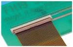
● 0.9mm high (30 pos. shown)
1. Low-profile 0.5mm pitch FPC/FFC Connectors
Miniaturization of portable equipment and personal
mobile devices has created increased demand for a low
profile, high density, and high reliability connectors.
17m
m
m
*The design of this connector has been made thinner and
smaller, with a height of 0.9mm and width of 3mm.
*PCB footprint: Reduced approximately 48% (as compared
with Hirose Electric's 0.5mm pitch FH12 Series
connectors)
*Connector weight: Reduced approximately 78% (as compared
with Hirose Electric's 0.5mm pitch FH12 Series connectors)
0.9mm
3m
Sep.1.2018 Copyright 2018 HIROSE ELECTRIC CO., LTD. All Rights Reserved.
Actuator color: Brown
● Can be mounted over conductive traces
2. Conductive traces on the PCB can run under
the connector
All bottom surface of the connector is solid, without any
exposure of the contact.
3. Proven Flip-Lock Actuator System assures
easy and reliable operation
Rotating actuator permits easy insertion and reliable
connection with the FPC & FFC.
Tactile sensation confirms complete mechanical locking of
the actuator and the electrical connection.
4. Accepts 0.2mm & 0.3mm thick FPC/FFC
No exposed contacts on the bottom of the connector.
The connector will also terminate with 0.2mm thick Flat
Flexible Cable (FFC).
5. Board placement with automatic equipment
Flat upper surface and tape and reel packaging facilitate
vacuum pick-up and placement. Standard reel packaging
contains 5000 connectors.
Enclosed construction
(No exposed contacts)
Metal fittings
(Leadless)
● Metal Fittings (Leadless Type)
No protrusions on
the sides allows
close side-by-side
board placement.
● Actuator Temporary Hold Mechanism
6. Wide range of contact counts
The contact positions available range from 4 to 50.
7. Satisfies Halogen-free requirements
All materials and substances used in this product comply
with the Halogen-free standards.
* Defined according to IEC61249-2-21
Br: 900ppm max, Cl: 900ppm max, Br+Cl: 1,500ppm max
Actuator stays open during insertion of the FPC/FFC.
2013.11w
1
�FH19C & FH19SC Series●0.5mm pitch, 0.9mm above the board, Flexible Printed Circuit & Flexible Flat Cable ZIF Connectors
■Product Specifications
Current rating 0.5 A (Note1)
Rating
Voltage rating 50 V AC
Recommended
Sep.1.2018 Copyright 2018 HIROSE ELECTRIC CO., LTD. All Rights Reserved.
FPC, FFC
Operating temperature range
-55ç to +85ç (Note 2)
Operating humidity range
Relative humidity 90% max. (No condensation)
Storage temperature range
-10ç to +50ç (Note 3)
Storage humidity range
Relative humidity 90% max. (No condensation)
FH19C Series
Thickness: = 0.2 ± 0.03mm Gold plated
FH19SC Series
Thickness: = 0.3 ± 0.03mm Gold plated
Item
Specification
1. Insulation resistance 500 M ohms min.
2. Withstanding voltage No flashover or insulation breakdown
100 m ohms max.
3. Contact resistance
*Including FPC/FFC conductor resistance
Conditions
1 mA
4. Durability
Contact resistance: 100 m ohms max.
(insertion/ withdrawal) No damage, cracks, or parts dislocation.
20 cycles
100 V DC
150 V AC/1 minute
5. Vibration
No electrical discontinuity of 1 μs or more.
Frequency: 10 to 55 Hz, single amplitude of
Contact resistance: 100 m ohms max.
No damage, cracks, or parts dislocation. 0.75mm, 10 cycles in each of the 3 directions
6. Shock
No electrical discontinuity of 1 μs. min.
Contact resistance: 100 m ohms max.
No damage, cracks, or parts dislocation.
Acceleration of 981 m/s2, 6 ms duration, sine halfwave waveform, 3 cycles in each of the 3 axis.
7. Humidity
(Steady state)
Contact resistance: 100 m ohms max.
Insulation resistance: 100 M ohms min.
No damage, cracks, or parts dislocation.
96 hours at temperature of 40ç and humidity of
90 to 95%
8. Temperature cycle
Contact resistance: 100 m ohms max.
Insulation resistance: 100 M ohms min.
No damage, cracks, or parts dislocation.
Temperature: -55ç / +15ç to +35ç / +85ç / +15ç to +35ç
Time
: -30 /
2 to 3
/ +30 / 2 to 3(Minutes)
5 cycles
9. Resistance to
soldering heat
No deformation of components affecting performance.
Reflow: At the recommended temperature profile
Manual soldering: 350ç±5ç for 5 seconds
Note 1: When passing the current through all of the contacts, use 70% of the current rating.
Note 2: Includes temperature rise caused by current flow.
Note 3: The term “storage” refers to products stored for long period of time prior to mounting and use. Operating Temperature
Range and Humidity range covers non- conducting condition of installed connectors in storage, shipment or during
transportation.Information
■Materials
Part
Material
Insulator
LCP
Contacts
Metal fittings
Phosphor bronze
Phosphor bronze
Finish
Color: Beige
Color: Brown (FH19C Series)
Color: Black (FH19SC Series)
Gold plated
Pure tin reflow plated
Remarks
UL94V-0
-------------
■Ordering information
FH 19 C - 30S - 0.5 SH (05)
1
2
3
4
5
6
1 Series name :
FH
5 Contact pitch : 0.5mm
2 Series No. :
19
6 Terminal type
3
FPC thickness : 0.2mm
FPC/FFC thickness : 0.3mm
C :
SC :
4 No. of contacts : 4 to 50
7
SH: SMT horizontal mounting type
7 Material and plating specifications :
FH19C : (10)...Gold plating with nickel barrier 5,000pieces/reel
(99)...Gold plating with nickel barrier 500pieces/reel
FH19SC : (09)...Gold plating with nickel barrier 5,000pieces/reel
(99)...Gold plating with nickel barrier 500pieces/reel
2
�FH19C & FH19SC Series●0.5mm pitch, 0.9mm above the board, Flexible Printed Circuit & Flexible Flat Cable ZIF Connectors
■Connector Dimension
[FH19C Series]
3
A±0.15
B
+0.15
0
0.5
(0.15)
2.5±0.15
A
Polarizing mark indicator
(0.5)
Number of contacts indicator
(130°)
(1.6)
Sep.1.2018 Copyright 2018 HIROSE ELECTRIC CO., LTD. All Rights Reserved.
(1)
0.15 G
0.9±0.1(Including contact terminal leads)
G
∞Number of contacts
0.5
(0.15)
(C: FPC insertion slot dimension)
2
1
0.15MAX
D±0.1
0.15MAX
(1.3)
1
2
S
2.15±0.2
Notes 1 The coplanarity of each terminal lead and metal fitting is within 0.1mm.
2 The contact terminal lead position indicates the dimension from the bottom surface of the insulator body.
3 Difference between terminal contact to be max. 0.1mm.
4 Packaged on tape and reel only. Check packaging specification.
5 Any discoloration of the plastic compound will NOT AFFECT form, fit or function of the connector.
6 After reflow, the terminal plating may change color, however this does not represent a quality issue.
Unit: mm
Part Number
CL No.
Number of Contacts
A
B
C
D
FH19C-04S-0.5SH(**)
580-0410-1-**
4
4
1.5
2.57
3.35
FH19C-05S-0.5SH(**)
580-0418-3-**
5
4.5
2
3.07
3.85
FH19C-06S-0.5SH(**)
580-0409-2-**
6
5
2.5
3.57
4.35
FH19C-07S-0.5SH(**)
580-0411-4-**
7
5.5
3
4.07
4.85
FH19C-08S-0.5SH(**)
580-0404-9-**
8
6
3.5
4.57
5.35
FH19C-09S-0.5SH(**)
580-0403-6-**
9
6.5
4
5.07
5.85
FH19C-10S-0.5SH(**)
580-0412-7-**
10
7
4.5
5.57
6.35
FH19C-12S-0.5SH(**)
580-0413-0-**
12
8
5.5
6.57
7.35
FH19C-13S-0.5SH(**)
580-0405-1-**
13
8.5
6
7.07
7.85
FH19C-15S-0.5SH(**)
580-0406-4-**
15
9.5
7
8.07
8.85
FH19C-17S-0.5SH(**)
580-0408-0-**
17
10.5
8
9.07
9.85
FH19C-20S-0.5SH(**)
580-0402-3-**
20
12
9.5
10.57
11.35
FH19C-21S-0.5SH(**)
580-0414-2-**
21
12.5
10
11.07
11.85
FH19C-24S-0.5SH(**)
580-0407-7-**
24
14
11.5
12.57
13.35
FH19C-27S-0.5SH(**)
580-0401-0-**
27
15.5
13
14.07
14.85
FH19C-30S-0.5SH(**)
580-0400-8-**
30
17
14.5
15.57
16.35
FH19C-34S-0.5SH(**)
580-0419-6-**
34
19
16.5
17.57
18.35
FH19C-40S-0.5SH(**)
580-0416-8-**
40
22
19.5
20.57
21.35
FH19C-50S-0.5SH(**)
580-0417-0-**
50
27
24.5
25.57
26.35
Note1: Embossed tape reel packaging (5,000 pieces/reel, 500 pieces/reel).
Order by number of reels.
3
�FH19C & FH19SC Series●0.5mm pitch, 0.9mm above the board, Flexible Printed Circuit & Flexible Flat Cable ZIF Connectors
[FH19SC Series]
3
A±0.15
0.5
(0.15)
2.5±0.15
(1)
0.15 G
+0.15
0
G
∞Number of contacts
0.5
0.93±0.1(Including contact terminal leads)
B
Sep.1.2018 Copyright 2018 HIROSE ELECTRIC CO., LTD. All Rights Reserved.
A
Polarizing mark indicator
(0.5)
5
(130°)
(1.6)
Number of contacts indicator
(0.15)
(C: FPC insertion slot dimension)
2
1
0.15MAX
D±0.1
0.15MAX
(1.3)
1
2
S
2.15±0.2
Notes 1
2
3
4
5
6
7
The coplanarity of each terminal lead and metal fitting is within 0.1mm.
The contact terminal lead position indicates the dimension from the bottom surface of the insulator body.
Difference between terminal contact to be max. 0.1mm.
Any discoloration of the plastic compound will NOT AFFECT form, fit or function of the connector.
The contacts are protruding. 0.03mm max. from the housing top surface.
Packaged on tape and reel only. Check packaging specification.
After reflow, the terminal plating may change color, however this does not represent a quality issue.
CL No.
Number of Contacts
A
B
C
D
FH19SC-12S-0.5SH(**)
580-0512-1-**
12
8
5.5
6.57
7.35
FH19SC-13S-0.5SH(**)
580-0518-8-**
13
8.5
6
7.07
7.85
FH19SC-14S-0.5SH(**)
580-0509-7-**
14
9
6.5
7.57
8.35
FH19SC-15S-0.5SH(**)
580-0503-0-**
15
9.5
7
8.07
8.85
FH19SC-16S-0.5SH(**)
580-0521-2-**
16
10
7.5
8.57
9.35
FH19SC-17S-0.5SH(**)
580-0504-3-**
17
10.5
8
9.07
9.85
FH19SC-18S-0.5SH(**)
580-0519-0-**
18
11
8.5
9.57
10.35
FH19SC-20S-0.5SH(**)
580-0502-8-**
20
12
9.5
10.57
11.35
FH19SC-21S-0.5SH(**)
580-0505-6-**
21
12.5
10
11.07
11.85
FH19SC-22S-0.5SH(**)
580-0506-9-**
22
13
10.5
11.57
12.35
FH19SC-24S-0.5SH(**)
580-0511-9-**
24
14
11.5
12.57
13.35
FH19SC-26S-0.5SH(**)
580-0510-6-**
26
15
12.5
13.57
14.35
FH19SC-27S-0.5SH(**)
580-0516-2-**
27
15.5
13
14.07
14.85
FH19SC-28S-0.5SH(**)
580-0513-4-**
28
16
13.5
14.57
15.35
FH19SC-30S-0.5SH(**)
580-0500-2-**
30
17
14.5
15.57
16.35
FH19SC-32S-0.5SH(**)
580-0514-7-**
32
18
15.5
16.57
17.35
Note1: Embossed tape reel packaging (5,000 pieces/reel, 500pieces/reel) .
Order by number of reels.
4
Unit: mm
Part Number
�FH19C & FH19SC Series●0.5mm pitch, 0.9mm above the board, Flexible Printed Circuit & Flexible Flat Cable ZIF Connectors
■Recommended PCB Land and Metal Mask Dimensions
[Common to FH19C & FH19SC Series]
Recommended metal mask thickness: 0.10 mm.
H
(3)
(0.15)
(0.2)
(0.15)
0.8±0.05
(0.05)
J±0.1
K±0.1
(A)
■Recommended FPC, FFC Dimensions
[Common to FH19C & FH19SC Series]
L±0.05
2R0
0.35±0.03(FPC)
0.3±0.03(FFC)
0.5±0.03
FH19C Series FH19SC Series
0.2±0.03
0.3±0.03
(X)
3.5 min. (Stiffener)
3.5 min. (Stiffener)
B±0.03
.2
0.5±0.07
2.5±0.3
(Exposed traces)
Sep.1.2018 Copyright 2018 HIROSE ELECTRIC CO., LTD. All Rights Reserved.
3.3±0.05
(0.15) (0.15)
0.5
(2.5)
0.8±0.05
B
∞Number of contacts
0.3±0.05 (Land)
0.1 H
0.25±0.05 (Metal mask)
Note 1: Stiffener dimension should be 3.5mm min., and X dimension should be 0.5mm for improved flexibility of FPC.
Unit: mm
Number of Contacts
4
5
6
7
8
9
10
12
13
14
15
16
17
18
A
4.0
4.5
5.0
5.5
6.0
6.5
7.0
8.0
8.5
9.0
9.5
10.0
10.5
11.0
B
1.5
2.0
2.5
3.0
3.5
4.0
4.5
5.5
6.0
6.5
7.0
7.5
8.0
8.5
J
3.1
3.6
4.1
4.6
5.1
5.6
6.1
7.1
7.6
8.1
8.6
9.1
9.6
10.1
K
3.9
4.4
4.9
5.4
5.9
6.4
6.9
7.9
8.4
8.9
9.4
9.9
10.4
10.9
L
2.5
3.0
3.5
4.0
4.5
5.0
5.5
6.5
7.0
7.5
8.0
8.5
9.0
9.5
Unit: mm
Number of Contacts
20
21
22
24
26
27
28
30
32
34
40
45
50
A
12.0
12.5
13.0
14.0
15.0
15.5
16.0
17.0
18.0
19.0
22.0
24.5
27.0
B
9.5
10.0
10.5
11.5
12.5
13.0
13.5
14.5
15.5
16.5
19.5
22.0
24.5
J
11.1
11.6
12.1
13.1
14.1
14.6
15.1
16.1
17.1
18.1
21.1
23.6
26.1
K
11.9
12.4
12.9
13.9
14.9
15.4
15.9
16.9
17.9
18.9
21.9
24.4
26.9
L
10.5
11.0
11.5
12.5
13.5
14.0
14.5
15.5
16.5
17.5
20.5
23.0
25.5
5
�FH19C & FH19SC Series●0.5mm pitch, 0.9mm above the board, Flexible Printed Circuit & Flexible Flat Cable ZIF Connectors
■FH19C & FH19SC Series FPC/FFC Construction (Recommended Specifications)
1. Using Single-sided FPC
FPC : Flexible Printed Circuit
Material Name
Covering layer film
Material
Polyimide
1 mil thick
Sep.1.2018 Copyright 2018 HIROSE ELECTRIC CO., LTD. All Rights Reserved.
Cover adhesive
(25)
(25)
(25)
3
3
35
35
Surface treatment
Copper foil
Cu
Base adhesive
Thermosetting adhesive
25
25
Base film
Polyimide
1 mil thick
25
25
Reinforcement material adhesive Thermosetting adhesive
30
30
75
175
193
293
1oz
Polyimide
FH19C : 3mil
FH19SC: 7mil
Total
FPC : Flexible Printed Circuit
Material Name
Covering layer film
Cover adhesive
Material
Polyimide
1 mil thick
Thickness (μm)
FH19C FH19SC
(25)
(25)
(25)
(25)
3
3
15
15
18
18
Surface treatment
Nickel under plated 1 to 5μm /
Gold plated 0.2μm
Through-hole copper
Cu
Copper foil
Cu
Base adhesive
Thermosetting adhesive
18
18
Base film
Polyimide
25
25
Base adhesive
18
18
Copper foil
Cu
18
18
Cover adhesive
Thermosetting adhesive
25
25
Polyimide
1 mil thick
25
25
Reinforcement material adhesive Thermosetting adhesive
25
50
25
100
197
297
Covering layer film
1/2oz
1 mil thick
1/2oz
Polyimide
Stiffener
FH19C : 1mil
FH19SC: 4mil
Total
3. Using FFC (Flexible Flat Cable)
(25)
Nickel under plated 1 to 5μm /
Gold plated 0.2μm
Stiffener
2. Using Double-sided FPC
Thickness (μm)
FH19C FH19SC
FFC : Flexible Flat Cable
Material Name
Material
Polyester film
Adhesive
Polyester thermoplastic type
(Nickel under plated / Gold plated), soft copper film
Adhesive
Polyester
Polyester
Thickness (μm)
FH19C FH19SC
(12)
(12)
(30)
(30)
35
35
30
30
12
12
Adhesive
Polyester
30
30
Stiffener
Polyester
100
188
Total
207
295
* Practical tolerance of thickness dimension is ±20μm (i.e., 187 to 227μm).
4. Precautions
1. This specification is a recommendation for the construction of the
FH19C/FH19SC Series FPC and FFC (t=0.2/0.3±0.03).
2. For details about the construction, please contact the FPC/FFC
manufacturers.
6
�FH19C & FH19SC Series●0.5mm pitch, 0.9mm above the board, Flexible Printed Circuit & Flexible Flat Cable ZIF Connectors
■Packaging Specifications
[Common to FH19C & FH19SC Series]
● Embossed Carrier Tape Dimensions
8±0.1
(3.3)
(4.3)
Unreeling direction
Flat surface for placement
with automatic equipment
(1)
)
●Reel Dimensions
(Ø1
3
(Ø80)
(R:INSIDE)
(Ø380)
Sep.1.2018 Copyright 2018 HIROSE ELECTRIC CO., LTD. All Rights Reserved.
(Q)
Ø1
.5
(0.3)
M±0.3
1.75±0.1
2±0.15
+
0.
0 1
4±0.1
N±0.1
(1.7)
(T:OUTSIDE)
End cection
Mounting cection
Embossed carrier tape
Blank cection
(10 pockets min.)
Lead cection (400 mm min.)
Blank cection
Top cover tape
(10 pockets min.)
Unit: mm
Number of Contacts
4
5
6
7
8
9
10
12
13
14
15
16
17
18
M
16
16
16
16
16
16
16
16
16
16
16
24
24
24
N
7.5
7.5
7.5
7.5
7.5
7.5
7.5
7.5
7.5
7.5
7.5
11.5
11.5
11.5
Q
4.3
4.8
5.3
5.8
6.3
6.8
7.3
8.3
8.8
9.3
9.8
10.3
10.8
11.3
R
17.4
17.4
17.4
17.4
17.4
17.4
17.4
17.4
17.4
17.4
17.4
25.4
25.4
25.4
T
21.4
21.4
21.4
21.4
21.4
21.4
21.4
21.4
21.4
21.4
21.4
29.4
29.4
29.4
Unit: mm
Number of Contacts
20
21
22
24
26
27
28
30
32
34
40
45
50
M
24
24
24
24
24
24
24
24
32
32
44
44
44
N
11.5
11.5
11.5
11.5
11.5
11.5
11.5
11.5
14.2
14.2
20.2
20.2
20.2
Q
12.3
12.8
13.3
14.3
15.3
15.8
16.3
17.3
18.3
19.3
22.3
24.8
27.3
R
25.4
25.4
25.4
25.4
25.4
25.4
25.4
25.4
33.4
33.4
45.4
45.4
45.4
T
29.4
29.4
29.4
29.4
29.4
29.4
29.4
29.4
37.4
37.4
49.4
49.4
49.4
Note: Embossed tape 32 mm or wider will have perforated feed holes on two sides.
7
�FH19C & FH19SC Series●0.5mm pitch, 0.9mm above the board, Flexible Printed Circuit & Flexible Flat Cable ZIF Connectors
■Recommended Temperature Profile
[For FH19C & FH19SC Series]
MAX 250ç
250
230ç
Sep.1.2018 Copyright 2018 HIROSE ELECTRIC CO., LTD. All Rights Reserved.
Temperature(ç)
200
HRS test condition
Solder method
Solder composition
:Reflow, IR/hot air
:Paste,
96.5%Sn/3.0%Ag/0.5%Cu
(Senju Metal Industry, Co.,
200ç
Ltd.’s Part
150
Number:M705-221CM5-3210.5)
150ç
Test board
:Glass epoxy
45mm∞100mm∞1.6mm thick
Land dimensions
Metal mask
:0.3mm∞0.8mm
:0.25mm∞0.8mm∞0.1mm
100
50
25ç (60 sec.)
90 sec. to 120 sec.
(60 sec.)
This temperature profile is based on the above
conditions.
Soldering
In individual applications the actual temperature may
vary, depending on solder paste type,
0
Start
Preheating
Time (Seconds)
volume/thickness and board size/thickness. Consult
tour solder paste and equipment manufacturer for
specific recommendations.
8
�FH19C & FH19SC Series●0.5mm pitch, 0.9mm above the board, Flexible Printed Circuit & Flexible Flat Cable ZIF Connectors
■Connector Operation and Precautions
Operation
1. FPC/FFC Termination procedure.
Connector installed on the board.
Precautions
1) Do not apply excessive force or use any type
of tool to operate the actuator.
Sep.1.2018 Copyright 2018 HIROSE ELECTRIC CO., LTD. All Rights Reserved.
1) Lift up the actuator. Use thumb or index finger.
2) The connector will assure reliable performance
when the actuator is open to 130° maximum.
Do not exceed this angle, as this may cause
permanent damage to the connector.
2) Assure that the FPC/FFC is fully inserted
parallel to mounting surface, with the
exposed conductive traces facing down.
FPC conductor surface
(Bottom side)
3) Rotate down the actuator until firmly closed.
It is critical that the inserted FPC/FFC is not
moved and remains fully inserted. Should
the FPC/FFC be moved, open the actuator
and repeat the process, starting with Step 1
above.
3) Insert the FPC/FFC straight into the insertion opening. Failing to follow this precaution can lead to
damaging the FPC/FFC and altering its connectivity.
ing
open
tion
r
e
s
in
·FFC
FPC
4) When you insert the FPC into the insertion opening, do not apply excessive pressure or scrape
the FPC on the bottom of the opening. Doing so
can lead to deformities of the contacts and can
hinder the performance of the connector.
2. FPC/FFC Removal
1) Lift up the actuator.
2) Carefully remove the FPC/FFC.
5) Application of excessive force to the inserted
FPC/FFC may cause damage to connector
and may affect the reliability of electrical connection.
If specific application requires continuous or repeated
pull or bend of the
inserted FPC/FFC,
assure that the
forces are NOT
transmitted directly
to the connector.
9
�FH19C & FH19SC Series●0.5mm pitch, 0.9mm above the board, Flexible Printed Circuit & Flexible Flat Cable ZIF Connectors
Sep.1.2018 Copyright 2018 HIROSE ELECTRIC CO., LTD. All Rights Reserved.
NOTES :
10
�FH19C & FH19SC Series●0.5mm pitch, 0.9mm above the board, Flexible Printed Circuit & Flexible Flat Cable ZIF Connectors
Sep.1.2018 Copyright 2018 HIROSE ELECTRIC CO., LTD. All Rights Reserved.
NOTES :
11
�Sep.1.2018 Copyright 2018 HIROSE ELECTRIC CO., LTD. All Rights Reserved.
FH19C & FH19SC Series●0.5mm pitch, 0.9mm above the board, Flexible Printed Circuit & Flexible Flat Cable ZIF Connectors
Powered by TCPDF (www.tcpdf.org)
USA:
HIROSE ELECTRIC (U.S.A.), INC. Headquarters
2688 Westhills Court, Simi Valley, CA 93065-6235
Phone : 1-805-522-7958
Fax : 1-805-522-3217
http://www.hiroseusa.com
USA:
HIROSE ELECTRIC (U.S.A.), INC. North California Office
20400 Stevens Creek Blvd., Ste 250, Cupertino, CA
95014
Phone : 1-408-253-9640
Fax : 1-408-253-9641
http://www.hiroseusa.com
USA:
HIROSE ELECTRIC (U.S.A.), INC. Detroit Office (Automotive)
37677 Professional Center Drive, Suite #100C
Livonia, MI 48154
Phone : 1-734-542-9963
Fax : 1-734-542-9964
http://www.hiroseusa.com
GERMANY:
HIROSE ELECTRIC EUROPE B.V. GERMAN BRANCH
Herzog-Carl-Strasse 4 D-73760 Ostfildern
(Scharnhauser Park)
Phone : 49-711-4560-02-1
Fax : 49-711-4560-02-299
http://www.hirose.de
THE NETHERLANDS:
HIROSE ELECTRIC EUROPE B.V.
Hogehillweg #8 1101 CC Amsterdam Z-O
Phone : 31-20-6557460
Fax : 31-20-6557469
http://www.hiroseeurope.com
UK:
HIROSE ELECTRIC EUROPE B.V. UK BRANCH
First Floor, St Andrews House, Caldecotte Lake
Business Park, Milton Keynes MK7 8LE
Phone : 44-1908-369060
Fax : 44-1908-369078
http://www.hirose.co.uk
CHINA:
HIROSE ELECTRIC CO., LTD. BEIJING REPRESENTATIVE OFFICE
A1001, Ocean International Center, Building 56# East 4th
Ring Middle Road, Chao Yang District, Beijing, 100025
Phone : 86-10-5165-9332
Fax : 86-10-5908-1381
http://www.hirose-china.com.cn
CHINA:
HIROSE ELECTRIC (SHANGHAI) CO., LTD.
1501-02, Cross Tower Building, 318 Fuzhou Road,
Huang Pu District, Shanghai 200001
Phone : 86-21-6391-3355
Fax : 86-21-6335-0767
http://www.hirose-china.com.cn
CHINA:
HIROSE ELECTRIC CO., LTD. SHENZHEN OFFICE
Room 09-13, 19/F, Office Tower Shun Hing Square, Di Wang Commercial Centre
5002, ShenNanDong Road, ShenZhen City, Guangdong Province, 518008
Phone : 86-755-8207-0851
Fax : 86-755-8207-0873
http://www.hirose-china.com.cn
HONG KONG:
HIROSE ELECTRIC HONGKONG TRADING CO., LTD.
Unit 1102 A&B, Energy Plaza, 92 Granville Road,
Tsim Sha Tsui East, Kowloon
Phone : 852-2803-5338
Fax : 852-2591-6560
http://www.hirose-hongkong.com.hk
TAIWAN:
HIROSE ELECTRIC TAIWAN CO., LTD.
103 8F, No.87, Zhengzhou Rd., Taipei
Phone : 886-2-2555-7377
Fax : 886-2-2555-7350
http://www.hirose-taiwan.com.tw
SINGAPORE:
HIROSE ELECTRIC CO., LTD.
10 Anson Road #26-16 International Plaza 079903
Phone : 65-6324-6113
Fax : 65-6324-6123
http://www.hirose-singapore.com.sg
KOREA:
HIROSE KOREA CO., LTD.
1261-10, Jeoungwhang-Dong, Shihung-City,
Kyunggi-Do 429-450
Phone : 82-31-496-7000,7124
Fax : 82-31-496-7100
http://www.hirose.co.kr
®
12
6-3,Nakagawa Chuoh-2-Chome,Tsuzuki-Ku,Yokohama-Shi 224-8540,JAPAN
TEL: +81-45-620-3526 Fax: +81-45-591-3726
http://www.hirose.com
http://www.hirose-connectors.com
The contents of this catalog are current as of date of 11/2013. Contents are subject to change without notice for the purpose of improvements.
�


 工商网监
湘ICP备2023018690号
工商网监
湘ICP备2023018690号
