Additional Resources:
Product Page
|
3D Model
date
09/27/2016
page
1 of 6
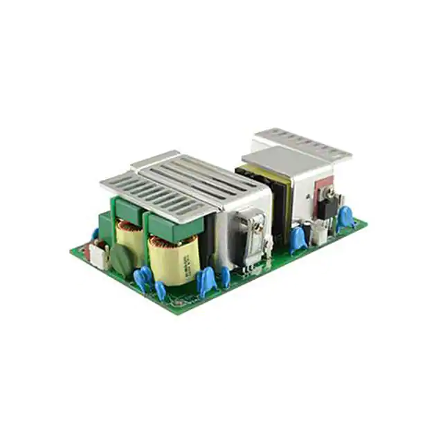
SERIES: VOF-185 │ DESCRIPTION: AC-DC POWER SUPPLY
FEATURES
•
•
•
•
•
•
•
•
•
up to 185 W continuous power
universal input voltage range
industry standard 3” x 5” footprint
power factor correction
low no load power consumption
over voltage, over current, and short circuit protections
output trim
UL/cUL and TUV safety approvals
efficiency up to 85%
MODEL
output
voltage
output
current
output
power1
ripple
and noise2
efficiency3
(Vdc)
max
(A)
max
(W)
max
(mVp-p)
typ
(%)
VOF-185-12
12
15.42
185
120
85
VOF-185-15
15
12.33
185
150
85
VOF-185-24
24
7.71
185
240
85
VOF-185-36
36
5.14
185
360
85
VOF-185-48
48
3.85
185
480
85
Notes:
1.
2.
3.
4.
Maximum output power of 185 W with forced air cooling (8.48 CFM), 111 W with convection cooling.
At full load, nominal input, 20 MHz bandwidth oscilloscope, using a 12” twisted pair wire terminated together with a 0.1 μF and 47 μF capacitor.
At full load, 230 Vac input, without external fan.
All specifications are measured at Ta=25°C, 230 Vac input voltage, and rated output load unless otherwise specified.
PART NUMBER KEY
VOF-185 - XX
Output Voltage
Base Number
cui.com
�Additional Resources:
Product Page
|
3D Model
CUI Inc │ SERIES: VOF-185 │ DESCRIPTION: AC-DC POWER SUPPLY
date 09/27/2016 │ page 2 of 6
INPUT
parameter
conditions/description
min
voltage
typ
90
frequency
47
current
at 115 Vac, full load
at 230 Vac, full load
inrush current
at 230 Vac, cold start
leakage current
at 264 Vac
power factor correction
at 230 Vac, full load
no load power consumption
at 230 Vac
input fuse
6.3 A / 250 V time delay fuse (included)
max
units
277
Vac
63
Hz
2.3
1.2
A
A
80
A
3.5
mA
0.5
W
max
units
0.9
OUTPUT
parameter
conditions/description
min
initial set point accuracy
line regulation
typ
±3
%
±0.5
%
±2
%
1,200
1,500
2,400
3,600
4,800
mVp-p
mVp-p
mVp-p
mVp-p
mVp-p
load regulation
from 100%~10% load
transient response
1 kHz, 100%~10% load
VOF-185-12
VOF-185-15
VOF-185-24
VOF-185-36
VOF-185-48
start-up delay time
at 115 Vac
at 230 Vac
3
2.5
s
s
start-up rise time
at 115 Vac, full load
50
ms
hold-up time
at 115 Vac, full load
adjustability
built in trim pot
10
ms
±5
swithching frequency
30
temperature coefficient
at 0~50°C
fan output
12 Vdc / 100 mA
%
300
±0.03
kHz
%/°C
PROTECTIONS
parameter
conditions/description
over voltage protection
clamped by TVS
min
typ
max
units
over current protection
hiccup, auto recovery
105
%
short circuit protection
hiccup, auto recovery
105
%
SAFETY & COMPLIANCE
parameter
conditions/description
isolation voltage
input to output
input to ground
output to ground
safety approvals
UL 60950-1, EN 60950-1, IEC 60950-1
EMI/EMC1
EN 55022: 2010 Class B, EN 61204-3:2000, EN
61000-6-3: 2007 +A1: 2011, EN 61000-3-2:
2006 +A2: 2009, EN 61000-3-3: 2008, EN 55024:
2010, EN 61000-6-1: 2007, ENV 50204: 1995, CE,
FCC
Notes:
min
typ
3,000
1,500
500
max
units
Vac
Vac
Vac
1. The power supply is considered a component which will be installed into final equipment. The final equipment still must be tested to meet the necessary EMC directives.
cui.com
�Additional Resources:
Product Page
|
3D Model
CUI Inc │ SERIES: VOF-185 │ DESCRIPTION: AC-DC POWER SUPPLY
date 09/27/2016 │ page 3 of 6
SAFETY & COMPLIANCE (CONTINUED)
parameter
conditions/description
class
class I
MTBF
as per MIL-HDBK-217F
RoHS
2011/65/EU
min
typ
max
units
250,000
hours
ENVIRONMENTAL
parameter
conditions/description
min
operating temperature
see derating curves
storage temperature
typ
max
units
-20
70
°C
-40
85
°C
operating humidity
non-condensing
20
90
%
storage humidity
non-condensing
20
90
%
operating altitude
10~3000Hz, 10 minutes per cycle, for 1 hour
along each of the X, Y, and Z axes
vibration & shock
5000
m
2
G
DERATING CURVES
Temperature Derating Curve
Load vs. Input Voltage
Temperature Derating Curve
Load vs. Temperature
with FAN 8.48 CFM
100
Ta=25°C
100
Load (%)
Load (%)
90
80
without FAN
60
50
80
60
40
40
20
20
-20
0
10
20
30
40
50
60
100
90
70
Ambient Temperature (°C)
110
120
277
Ambient Temperature (°C)
EFFICIENCY CURVES
VOF-185-12 Efficiency Curve
(Efficiency vs. Load Current at 230 Vac)
VOF-185-15 Efficiency Curve
(Efficiency vs. Load Current at 230 Vac)
95
95
93
91
91
89
89
Efficiency (%)
Efficiency (%)
93
87
85
83
81
79
85
83
81
79
230 Vac
Vac
230
230 Vac
Vac
230
77
77
75
87
75
10
20
30
40 50 60 70 80
Load Current (%)
90
10
100
cui.com
20
30
40 50 60 70 80
Load Current (%)
90
100
�Additional Resources:
Product Page
|
3D Model
CUI Inc │ SERIES: VOF-185 │ DESCRIPTION: AC-DC POWER SUPPLY
date 09/27/2016 │ page 4 of 6
EFFICIENCY CURVES (CONTINUED)
VOF-185-36 Efficiency Curve
(Efficiency vs. Load Current at 230 Vac)
95
95
93
93
91
91
89
89
Efficiency (%)
Efficiency (%)
VOF-185-24 Efficiency Curve
(Efficiency vs. Load Current at 230 Vac)
87
85
83
81
79
10
20
30
40 50 60 70 80
Load Current (%)
90
81
75
100
95
93
91
Efficiency (%)
83
230 Vac
Vac
230
77
VOF-185-48 Efficiency Curve
(Efficiency vs. Load Current at 230 Vac)
89
87
85
83
81
230 Vac
Vac
230
79
77
75
85
79
230 Vac
Vac
230
77
75
87
10
20
30
40 50 60 70 80
Load Current (%)
90
100
cui.com
10
20
30
40 50 60 70 80
Load Current (%)
90
100
�Additional Resources:
Product Page
|
3D Model
CUI Inc │ SERIES: VOF-185 │ DESCRIPTION: AC-DC POWER SUPPLY
date 09/27/2016 │ page 5 of 6
MECHANICAL
parameter
conditions/description
dimensions
127 x 76.2 x 39.6
min
typ
max
units
mm
weight
0.36
cooling
external fan
AC input
CN1 mates with Molex 09-50-7031 housing with
Molex 2478 series crimp contact or equivalent
DC output
CN2 mates with Molex 09-50-7101 housing with
Molex 2478 series crimp contact or equivalent
Auxiliary (Fan) output
Fan mates with JST XHP-2 housing with JST
SXH-001T-P0.6 contact or equivalent
kg
MECHANICAL DRAWING
127.00 [5.00]
115.60 [4.55]
units: mm [inch]
tolerance: ±0.3 mm
5.70 [0.22]
CN1
L
2
NP
3
N
CN2
CN1
1
2
3
1
2
3
4
5
6
7
8
9
10
PIN
Function
1
+Vo
2
+Vo
3
+Vo
4
+Vo
5
+Vo
6
-Vo
5.50 [0.22]
7
-Vo
1.30 [0.05]
8
-Vo
9
-Vo
10
-Vo
CN2
1
2
25.00 [0.98]
Function
1
76.20 [3.00]
65.20 [2.57]
PIN
50.00 [1.97]
PIN
Function
1
+FAN
2
-FAN
35.00 [1.38]
CN3 (FAN)
1.60 [0.06]
3.00 [0.12]MAX(LEAD)
cui.com
CN3
FAN CONNECTOR
FAN
Ø4.0(4PLCS)
MOUNTING HOLE
CHASSIS GROUND
8.48CFM
AIR FLOW
DIRECTION
0.80 [0.03]
�Additional Resources:
Product Page
|
3D Model
CUI Inc │ SERIES: VOF-185 │ DESCRIPTION: AC-DC POWER SUPPLY
date 09/27/2016 │ page 6 of 6
REVISION HISTORY
rev.
description
date
1.0
initial release
06/27/2016
1.01
added efficiency curves
09/27/2016
The revision history provided is for informational purposes only and is believed to be accurate.
Headquarters
20050 SW 112th Ave.
Tualatin, OR 97062
800.275.4899
Fax 503.612.2383
cui.com
techsupport@cui.com
CUI offers a two (2) year limited warranty. Complete warranty information is listed on our website.
CUI reserves the right to make changes to the product at any time without notice. Information provided by CUI is believed to be accurate and reliable. However, no responsibility is
assumed by CUI for its use, nor for any infringements of patents or other rights of third parties which may result from its use.
CUI products are not authorized or warranted for use as critical components in equipment that requires an extremely high level of reliability. A critical component is any component of a
life support device or system whose failure to perform can be reasonably expected to cause the failure of the life support device or system, or to affect its safety or effectiveness.
�


 工商网监
湘ICP备2023018690号
工商网监
湘ICP备2023018690号
