Buffering: Electrolytic caps.
instead of accumulators
CB
scheme
Data sheet
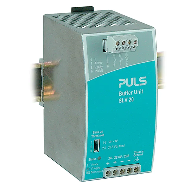
SLV20.200
IEC60950
• Buffering for 24V loads
• Minimum hold-up time: 0.2s/20A
(max. buffer time depends on load)
• Fit for industrial use: Energy storage
in electrolytic caps., no accumulators
• Clear status indication by Status LED
and signalling terminals
UL508 LISTED
IND. CONT. EQ.
18 WM, 60°C
UL60950 E137006
CUL/CSA-C22.2
No 60950
EMC and
Low Volt.
Directive
Short description
The buffer unit is a supplementary device for regulated DC 24V power
supplies. It buffers load currents during typical mains faults and switching events or load peaks.
Working principle
Charge
Buffer
In times when the power supply proviDC
des sufficient voltage, the buffer unit
Discharge
stores energy in integrated electrolytic
capacitors. In case of a mains voltage fault, this energy is released again
in a regulated process.
Bridges mains faults without
AC
interruption
Statistics show that 80 percent of all
DC
mains faults last less than 0.2s. These
Buffer unit
mains faults are completely bridged
by the buffer unit and will have no
influence on the DC power (startup-delay of power supply used might
be taken under consideration. This increases the reliability of the system
as a whole.
Extended hold-up time
Once the main power fails or is swit- AC
ched off, the buffer unit will contiDC
nue to provide the load current for a
Buffer unit
defined period of time. Process data
can be saved and processes can be
terminated before the DC power switches off. Controlled restarts are
subsequently possible.
Easy to handle, expandable and
maintenance-free
The buffer unit does not require any
control wiring. It can be added parallel to the load circuit at any given
point. Any given number of buffer units can be switched parallel to
increase the output capacity or the hold-up time. The dual terminals allow for easy wiring. In addition, there is a housing connection.
Short Overview - Technical Data
Short Overview - Technical Data
Rated voltage
DC 24V
Idling input current
typ. 80mA
Voltage range
DC 24...28.8V
Power dissipation
typ. 1.9W
Buffered voltage
selectable by front jumper setting
Vin -1V: 23 - 27.8V (variable threshold)
22.5V fixed: 22.5V (fixed threshold)
Degree of protection
IP20 (EN 60529)
Dimensions (W x H x D) 64mm x 124mm x 102mm (without DIN rail)
Weight
Reversed power
immunity
max. +35V
Protection against
polarity reversal
max. -35V
Charging current
20A
Charging time
18...27s (primary charge)
Hold-up time
• minimum
• typical
see diagramm (page 2)
0,2s (22,5V/20A) or 28s (22,5V/100mA)
0,31s (22,5V/20A) or 43s (22,5V/100mA)
740g
Safety
Terminal voltage
SELV, IEC/EN 60950
Classification
PELV (IEC364-4-41)
PELV (EN 60204)
Isolation resistance
5MOhm (terminal→housing)
Degree of protection
IP20 (EN 60529)
PELV (EN50178)
Penetration protection > 3.5 x 3.5 mm
Internal fusing
none
Galvanic isolation
to signal path
500V
Order information
slv20e200 Rev. C 040527
Order number
Description
SLV20.200
XF-1x4s/270-60
SLZ11
SLZ02
DIN rail electrolytic capacitor buffer unit
Mating connector for signalling terminals (part of delivery)
Adapter for S7-300 rail
Wall mounting set (two pcs. per package)
1/4
�Data sheet
SLV20.200
Hold-up time
Technical Data
Buffer Charging
Charging delay time
typ. 4s
Charging current
0.4...0.6A
Charging time
18...27s (primary charge / cold start)
Buffer Operation
Rated output current
20A
Current limitation
>20A
Hold-up time
• minimum
• typical
see diagramm (page 2)
0,2s (22,5V/20A) or 28s (22,5V/100mA)
0,31s (22,5V/20A) or 43s (22,5V/100mA)
To increase buffer current and/or extend hold-up time any given number of buffer unit can be switched parallel
(max. load per terminal = 30A)
Activation threshold
“22.5V fixed”
Buffering starts if terminal voltage 1V
Buffers are discharged, no external voltage or
external voltage 1V
• Pos. 2-3: DC22.5V fixed. Voltage buffering starts at Vin
很抱歉,暂时无法提供与“SLV20.200”相匹配的价格&库存,您可以联系我们找货
免费人工找货- 国内价格 香港价格
- 1+4268.766731+531.20316
