Additional Resources:
Product Page
rev.
page
1 of 3
date
04/2010
U
N
features
· Designed for easy application of board-mount DC-DC
Converters
- Provides a PCB to mount the converter
- Includes screw terminals for input and output connections
- Includes all mounting hardware
- Can be DIN rail mounted with (Optional) mounting
adapter
- Includes following features:
o Input fuse
o Input transient protection
o Input reversal protection
o Meet EN55022 class B conducted emissions*
o Output trimming capable with (Optional) trim
potentiometer - must be purchased
seperately and installed onboard.
ED
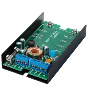
DESCRIPTION: Converter Kit
PART NUMBER: UF224
TI
*tested at 25°C
Description
Input
Voltage
9-18VDC
Voltage Protection
Threshold
20V
D
IS
C
- Model
Number
UF224S18
O
N
The UF224 kit is a value added item designed to facilitate easy application of 2"X2" sized board mount
DC-DC converters. It includes all components needed to use the converter, removing the need to procure PCB, metal frame, mounting hardware, filtering and protection components. For basic operations,
only the converter needs to be selected and procured separately. For additional output adjustment, a
seperate trim potentiometer can be purchased and installed onboard. UF224S kits are designed for
single-output converters.
Input Fuse 3
5A
Applicable V-INFINITY
DC-DC Converters¹
VCD30-D12-SXX
Applicable V-INFINITY
DC-DC Converters²
VCQ15-Q24-SXX
PTK15-Q24-SXX
VCQ15-Q48-SXX
PTK15-Q48-SXX
UF224S36
9-36VDC
39V
3A
VCD30-D24-SXX
VCQ15-Q24-SXX
PTK25-D24-SXX
PTK15-Q24-SXX
UF224S75
9-75VDC
82V
1A
VCD30-D48-XXX
VCQ15-Q48-SXX
PTK25-D24-SXX
PTK15-Q48-SXX
Notes:
1. The acceptable input voltage is the range suitable for the U-frame Kit only. It is OK to use a converter with a wider input
range as long as the input voltage applied does not exceed the kit’s acceptable input voltage range.
2. These converters actually have input ranges that exceed the respective U-frame kit's input range but are still acceptable for
use as long as the Kit's Acceptable Input Voltage range is not exceeded.
3.Use 5mm X 20mm fast blow type fuse.
20050 SW 112th Ave. Tualatin, Oregon 97062 phone 503.612.2300 fax 503.612.2383
www.v-infinity.com
�Additional Resources:
Product Page
rev.
2 of 3
date
04/2010
PIN ASSIGNMENTS
+Vout:
-Vout:
N.C.:
+ Input
- Input
Remote control to turn output On/Off
Output fine tuning
+ Output
- Output
No connection
U
Environment Conditions
ED
DESCRIPTION: Converter Kit
PART NUMBER: UF224
+Vin:
-Vin:
On/Off:
Trim:
page
Operating temperature range
Storage temp range
Humidity
-25 ~ 70°C
-25 ~ 85°C
10 ~ 90% RH, non-condensing
N
Parts List
D
IS
C
O
N
TI
1. PCB assembly - partially completed
2. U-frame
3. 4x M3 machine screws
20050 SW 112th Ave. Tualatin, Oregon 97062 phone 503.612.2300 fax 503.612.2383
www.v-infinity.com
�Additional Resources:
Product Page
rev.
page
3 of 3
date
04/2010
DESCRIPTION: Converter Kit
PART NUMBER: UF224
5.
6.
7.
8.
Select appropriate converter and UF224 kit according to the model configurations table.
Locate the partially completed assembly
Remove the 4x M3 screws and take out PCB
If output trimming is needed, install a top-mount 5KΩ trim pot. Available from Digikey, part # 3306F502-ND or 307UC502E-ND.
Insert and solder converter. Trim off excess leads as needed.
For DIN rail applications, secure the DIN rail adapter Kit (optional, model # VDRP-03). Skip this step
for non-DIN rail mounting applications.
Secure PCB assembly to the U-frame with the 4x M3 screws.
Connect input wires and output leads.
U
1.
2.
3.
4.
ED
Assembly Instructions:
N
Application Notes:
1. Input voltage
TI
It is important to ensure the input voltage measured at the converter input pins is within the range
for that converter. Make sure wire losses and voltage ripples are accounted for. One possible problem is driving the converter with a linear unregulated power supply. For example, if the average voltage measured by a DMM is 9V, with a
voltage ripple of 3Vpp, the actual input can swing from 7.5V to 10.5V. This will be outside the range of a 9-18V converter and it may not function properly. On the other end, make sure the actual input voltage does not exceed the highest
voltage allowed by either the U-frame kit or the converter.
2. Lead wires
3. Input current
N
Make sure the input and output wires are of adequate AWG size to minimize voltage drop, and ensure the voltage
across the input terminals is above the converter's rated minimum voltage at all times. It
is recommended to have the wire pairs twisted, respectively for the input pair and the output pair, so as to minimize
noise pickup.
IS
C
O
The input voltage source must be able to provide enough current to the converter, or it may not start up or operate properly. A typical symptom is not starting or unusually low output voltage. In general, it is recommended to be able to provide at least:
η *Vmin)
Ipeak = 150%*Pout/(η
where Pout is the maximum output power, Vmin is the minimum input voltage and η is the converter's efficiency. As an
example, for PTK15-Q24-S5 to operate with 10~36V input, 15W output and an efficiency of 78%, the minimum source
current is recommended to be:
Ipeak = 150% * 15 / (78% * 10) = 2.88A.
4. Input fuse
For various protection functions, a fast-acting input fuse has been installed with the following current
ratings:
UF224S18
UF224S36
5.0A
3.0A
UF224S72
1.0A
D
However, if the input range is well defined, the standard fuse may be replaced with a smaller fuse. The fuse should be
chosen to allow for the maximum current at the lowest input voltage, as shown in this equation:
η*Vmin)
Ipeak = 150%*Pout/(η
As an example, consider a 15W converter with 75% efficiency. If the actual input voltage range is 16~28V, the maximum input current is Ipeak = 150%*15/(75% * 16) = 1.875A.
The preinstalled fuse can be replaced with a 2A fuse in this situation.
20050 SW 112th Ave. Tualatin, Oregon 97062 phone 503.612.2300 fax 503.612.2383
www.v-infinity.com
�Additional Resources:
Product Page
rev.
page
4 of 3
date
04/2010
DESCRIPTION: Converter Kit
PART NUMBER: UF224
ED
5. Input OVP
To suppress voltage transients of short durations, the kit includes a Zener diode. For converter inputs
of up to 18V, the Zener diode used has a rated breakdown voltage of 20V. For converter inputs of
up to 36V, the Zener diode has a rated voltage of 39V. For inputs up to 72V, the Zener voltage rated is 82V. Notice,
however, that these Zener diodes can only dissipate a small amount of power. It is
necessary to ensure the input voltage does not exceed the maximum rated converter input. Otherwise
the converter and the Zener diode may suffer permanent damage.
U
6. Input reversal
N
If the input voltage is reversed for any reason, the built-in protection circuits in the UF224 kit will limit
the reverse voltage to one diode drop or no more than 1V. The input fuse will open and thus remove
power from the converter. Check the wiring and make corrections as needed. The input fuse will need
to be replaced. Make sure the new fuse is of the same type and rating.
7. Output trimming (optional)
8. Output OCP and short-circuit
TI
The UF224 Kit provides the space and pads for a trimming potentiometer. To adjust the output voltage, install a 5KΩ
potentiometer, (Digikey part # 3306F-502-ND or 307UC502E-ND or equivalent). The potentiometer is not needed if no
trimming function is desired. Please note that only converters listed in the Model Configurations table can achieve output trimming.
9. Output OVP
N
Output overload and short circuit protections are provided by the converter itself only. Please see the
converter datasheet for reference.
Output over-voltage protection is provided by the converter itself only. Refer to converter datasheet.
10. Output On/Off control
11. Isolation
O
The converter output can be enabled or disabled through the On/Off pin. Refer to converter data sheet.
IS
C
The input and output of the converter are electrically isolated. The isolation voltage rating is the same as that of the converter. Refer to converter data sheet.
12. Input filtering and EMI interference
The UF224 kit has built-in components for input filtering, leading to reduced current ripple and the associated EMI interference. The kits are designed to meet EN55022 class B conducted standards. If the entire system powered by this converter kit needs to pass an EMI standard, it is recommended to have entire system tested against that standard.
13. Output filtering
D
The UF224 kit has a small output capacitor to help reduce ripple and noise.
All specifications typical at nominal line, full load and 25°C unless otherwise noted.
V-Infinity reserves the right to make changes to its products or to discontinue any product or service
without notice, and to advise customers to verify the most up-to-date product information before placing orders. V-Infinity assumes no liability or responsibility for customer's applications using V-Infinity
products other than repair or replacing (at V-I's option) V-Infinity products not meeting V-I's published
specifications. Nothing will be covered outside of standard product warranty.
20050 SW 112th Ave. Tualatin, Oregon 97062 phone 503.612.2300 fax 503.612.2383
www.v-infinity.com
�


 工商网监
湘ICP备2023018690号
工商网监
湘ICP备2023018690号
