NEW
New Connectors For Low Profile Power Supply
RP34L Series
Receptacle installed height
RP34L
Existing RP34
(3-contact type) (2-contact type)
Fig.-➀
■Features
Mated Size
1. Low profile:
These receptacles are designed with their installation heights to
be shorter than those of conventional RP34 series, such as
6.1mm (for 2-core type) and 5mm (for 3-core type). (See Fig.-1.)
2. Space saving:
Both 2 and 3 position receptacles are miniaturized to 7mm in
depth, resulting in a small board mounting area.Please refer
Fig.-2 and Fig.-3.
3. With snap-lock mechanism:
Audible click when connector is fully mated.
RP34L-5PA-2SC(✽✽✽✽) & RP34L-5R-2PD
4. Tight fit:
Designed to fit snugly in all three directions.
This 2 contact plug is an over-molded (i.e., cable-integrated form) type.
Recommended cable diameter is Ø3.5mm.
Fig.-➁
5. Sequence structure:
The 3 contact type has sequenced mating so that one pin
makes contact as a ground terminal before the other contacts
engage.
Mating Size
6. No Mismating
Two polarized keys prevent any insertion error.
7. Ease of Mating
An arrow on the top of the plug shows the proper direction for
insertion.
■Applications
Notebook PCs, portable remote terminals, AV equipment, etc.
RP34L-5P-3SC & RP34L-5R-3PD
This 3-contact plug is a fabricated type.
Recommended cable diameter is Ø4mm.
99.4
Fig.-➂
1
�■Product Specifications
RATINGS
Rated Current
5A
Available Temp. Range
-25ç~+85ç
Rated Voltage
AC30V,DC42A
Storage Temp. Range
-10ç~+60ç
Description
Specifications
1.contact resistance
Requirements
Should be measured at DC 1A.
30mø or less
2.insulation resistance 1000mø or more
Should be measured at DC 100V.
3.voltage resistance
AC 150V for 1 minute
No flashover/dielectric4.vibration Breakdown
4.vibration resistance No instantaneous electric Disconnection of 10µs or More 10~55Hz, one-sided amplitude 0.75mm, 3 directions for 2hours, respectively
5.temperature cycle
-55ç for 30 min./normal temp. for 10~15 min./+85ç
for 30 min./normal temp. for 10~15 min. 5 cycles
Insulation resistance:100mø or more
6.corrosion resistance No excessive corrosion
For 48 consecutive hours in 5% salt water
7.Duration against consecutive
Contact resistance:60mø or less
plugging/unplugging.
5,000 time
Note.1) Above-stated specifications are typical of this series. For part specific data, please consult factory.
■Material Quality
Description
2 position receptacle
2-position plug
3-position receptacle
Material
Remarks
Phosphor bronze
Solder-plating
Dielectric
Nylon resin
Black color
Terminal
Brass
Palladium-plating
Cover
Vinyl chloride resin
Black color
UL94V-0
Insert insulator
Nylon resin
Black color
UL94HB
Terminal
Phosphor bronze
Metal fixture
Phosphor bronze
Solder-plating
Insulator
PPS resin
Black color
Terminal
Brass
Palladium-plating
Polycarbonate resin
Black color
UL94V-0
Cover
3-position plug
Processing
Metal fixture
UL94HB
UL94V-0
Vinyl chloride
Black color
UL94V-0
Insulator
PPS resin
Black color
UL94V-0
Terminal
Phosphor bronze
Palladium-plating
■Product Name Configuration
This is available for you to determine the product specifications from a part number, not to produce part numbers.
When ordering, please select from existing part numbers shown in page 3-4 of this catalog.[For plugs, Hirose will
produce cable assemblies to customer specifications. Please consult Hirose for quote.]
RP34L - 5 PA - 2 SC
1
1
Series name: RP34L
2
Shell: 5-shell.size
2
3 Type:
Receptacle: R
Assembled straight plug: P
Assembled right angle plug: LP
Cable-integrated forming straight
plug: PA
2
3
4
(✽ ✽ ✽ ✽ )
5
6
4 Number of positions:
Shows the numberof terminals.2contacts.3 contacts
5 Type of contact:
PD: dip-solder male terminal
SC: crimp-style female terminal
6 Cable length:(✽✽✽✽) depends on
each cable.
�■Receptacles
●2-position
RP34L-5R-2PD
●3-position
RP34L-5R-3PD
HRS No.
Parts No.
113-5154-6-00
RP34L-5R-2PD
113-5157-4-00
RP34L-5R-3PD
3
�■Plugs
■RP34L-5PA-2SC(1857)
■RP34L-5P-3SC
■RP34L-5LP-3SC
4
HRS No.
Parts No
113-5153-3-00
RP34L-5PA-2SC(1857)
113-5158-7-00
RP34L-5P-3SC
113-5161-1-00
RP34L-5LP-3SC
�■Crimp Terminal
■RP34L-SC1-212(01)
HRS No.
Parts No
113-5151-8-01
RP34L-SC1-212(01)
■Applicable Tools
TYPE
HRS No.
Parts No.
Conformant terminal
Conformant Cable
Manual crimping tool
--------------
HT-102/RP34L-SC1-212
RP34L-SC1-212(01)
AWG#18~#22
--------------
--------------
RP34L-SC1-212(01)
AWG#18~#22
Automatic
901-0005-4
CM-105
Crimper body
901-2043-4
AP105-RP34L-SC1-212
Cable crimping tool
150-0074-1
RP34-TC-01
--------------
Drawing tool
150-0039-0
RP6-SC-TP
--------------
Crimper
Ø4
--------------
5
�■Assembly Instructions(3-Position Plug)
●Straight Plug
1. First, pull the bushing through the terminalprocessed cable to crimp and wire that terminal.
2. Insert such crimped/wired terminal into the terminal
hole of S insulation P case.Then verify that the
crimp terminal is firmly engaged in the terminal hole
of S insulation P case by pulling the cable slightly.
In such cases as incorrect wiring, insert the
drawing jig (RP6-SC-TP) from the fitting section to
draw the terminal out of wiring side and rearrange it.
3. Next, crimp the clamp to the cable with an
applicable tool (RP34-tc-01).
4. Install the convex section of S insulation P case in
the cord tube(B) by adjusting to its round hole.
5. Then put the rim of clamp into the concave section
of cord tube(B), and install bushing/clamp in cord
tube(B).
6. Install cord tube(A) in cord tube(B). At that time,
verify that four claw sections of cord tube(B) are
mounted on the square hole section of cord
tube(A).
●Right Angle Plug
1. The right angle plug can also be assembled by
using the same procedure as the straight plug.
6
�■Precautions
1. Use the connector section with its panel held down so as not to have excessive load.For 2-contact type, hold the
outer shellsection of the receptacle, and for 3 contact type, the outer shell section of the plug.
2. After connector assembly, cable must not be pulled over 30N in the arrow-indicated direction. Be careful not to add
excessive tensile load because it will lead the damage of connectors.
7
�8
The contents of this catalog are current as of April 1999. Contents are subject to change without notice for the purpose of improvements.
�
很抱歉,暂时无法提供与“RP34L-5PA-3SC”相匹配的价格&库存,您可以联系我们找货
免费人工找货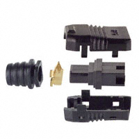


 工商网监
湘ICP备2023018690号
工商网监
湘ICP备2023018690号
