FWP322512A L Series Engineering Specification
1. Scope
Feature
z High saturation current realized by material properties and structure design
z Low DC resistance to achieve high conversion efficiency and lower temperature rising
z Low Profile: 3.2 mm × 2 . 5 mm × 1 . 2 mm.
z Magnetically shielded structure to accomplish high resolution in EMC protection.
z Halogen free, Lead Free, RoHS Compliance.
Applications
FWP322512A L series is generic applied in portable DC to DC converter line.
z Smart phone, PAD
z DC/DC converter
z Thin-type power supply module,
2. Explanation of Part Number
F W P
3 2 2 5
1 2
A
2 R 2
M
L
1
2
3
4
5
6
7
♦
♦
♦
♦
♦
♦
♦
1 : Series Name: Wire-wound type power inductor
2 : Size Code: The first two digitals: length(mm), The last two digitals: width(mm)
3 : Thickness in mm
4:Material code: Iron powder
5:Initial inductance value: 2R2 = 2.2 μH
6:Model code, Tolerance of Inductance ±20%.
7:Electrode type.
FWP322512A L Series Engineer Specification
All Specifications are subject to change without notice.
Version: A4
Page 1 of 9
�3. Construction & Dimensions
3.1. End termination: Ni/Sn
3.2. Construction & Dimension :
L
[mm]
W
[mm]
3.2±0.2
2.5±0.2
W1
[mm]
2.3±0.2
T
[mm]
E
[mm]
1.1±0.1
0.6±0.2
3.3. Recommend Land Pattern Dimensions :
B
A
[mm]
A
2.5typ
B
[mm]
C
[mm]
1.7typ
3.2typ
C
4. General specifications
4.1. Temperature Specifications
Operating Temperature range
Storage Temperature range
:
-40℃ to +125℃
: -50℃ to +125℃
* The detail operating temperature describing can refer to 5.1 (7).
FWP322512A L Series Engineer Specification
All Specifications are subject to change without notice.
Version: A4
Page 2 of 9
�5. Performance Characteristics
5.1. Specifications
Part Number
FWP322512A-R47ML
FWP322512A-R68ML
FWP322512A-1R0ML
FWP322512A-2R2ML
FWP322512A-4R7ML
FWP322512A-6R8ML
Li [μH]
Initial
inductance
@1mA
RDC [mΩ]
DC Resistance
Irms [A]
Isat [A]
Saturation Current Heat Rating Current
Typical Maximum Typical Maximum Typical Maximum
0.47
0.68
1.0
2.2
4.7
6.8
15
16
25
60
150
190
19
20
32
72
168
210
7.0
5.8
5.0
3.5
2.4
2.1
7.7
6.2
5.5
4
2.8
2.4
5.8
5.3
4.9
3
1.7
1.5
Note 1: Customized design is available, please contact us.
Nore 2: All test referenced to 26℃ ambient
Note 3: Inductance tolerance +/- 20%
Note 4: Inductance is measured with Agilent® LCR meter 4285A. Test frequency at 1MHz.
Note 5: DC resistance is measured with HIOKI® micro-ohm meter RM3542-01.
Note 6: Isat means that DC current will cause a 30% inductance reduction form initial value.
Note 7: Irms means that DC current will cause coil temp. rising to 40℃ whichever is smaller.
Note 8:Withstand voltage is 20V DC.
FWP322512A L Series Engineer Specification
All Specifications are subject to change without notice.
Version: A4
Page 3 of 9
5.2
4.7
4.4
2.7
1.4
1.2
�5.2. Current Characteristic
FWP322512A-R47ML
FWP322512A-R68ML
FWP322512A-1R0ML
FWP322512A-2R2ML
FWP322512A-4R7ML
FWP322512A L Series Engineer Specification
All Specifications are subject to change without notice.
FWP322512A-6R8ML
Version: A4
Page 4 of 9
�6. Reliability and Test Condition
Test item
Test condition
Criteria
1. More than 95 % of terminal
electrode should be covered
1. Solder temperature : 260 ± 5℃ with new solder
2. No mechanical damage
Resistance to Solder Heat 2. Flux : Rosin
3. DIP time : 10 ± 1 sec
3. Inductance value should be
within ± 20 % of the initial
value
1. Reflow temperature : 245℃ It
1. No mechanical damage
shall be Soldered on the
2. Soldering the products on
substrate applying direction
Adhesive Test
PCB after the pulling test
parallel to the substrate
force > 5 N
2. Apply force(F) : 5 N
3. Test time : 10 sec
1. Temperature:-50 ~ 125℃ For
30 minutes each
1. No mechanical damage
2. Cycle: 500 cycles
2. Inductance should be
Temperature Cycle
3. Measurement: At ambient
within ±20% of the initial
temperature 24 hours after test
value
completion
1. Temperature: 85 ± 2℃
2. Testing time: 500 hrs
1. No mechanical damage
3. Applied current: Full rated
2. Inductance should be
Dry Heat Test
current
within ± 20% of the initial
4. Measurement: At ambient
value
temperature 24 hours after test
completion
1. Temperature: 60 ± 2℃
2. Humidity: 90-95 % RH
1. No mechanical damage
3. Applied current: Full rated
2. Inductance should be
current
within ±20% of the initial
Humidity Test
4. Testing time: 500 hrs
value
5. Measurement: At ambient
temperature 24 hours after test
completion
FWP322512A L Series Engineer Specification
All Specifications are subject to change without notice.
Version: A4
Page 5 of 9
�7. Taping Package and Label Marking
7.1. Carrier tape dimensions
mm
A0
B0
K0
t
1.80±0.1
2.20±0.1
1.15±0.1
0.22±0.05
7.2. Taping reel dimensions
PART SIZE
(EIA SIZE)
3225
(1210)
Qty.(pcs)
3,000
BOX
5 reels / inner box
FWP322512A L Series Engineer Specification
All Specifications are subject to change without notice.
Version: A4
Page 6 of 9
�7.3. Taping specifications
There shall be the portion having no product in both the head and the end of
taping, and there shall be the cover tape in the head of taping.
7.4. Label Marking
The label specified as follows shall be put on the side of reel.
(1) Part No.
(2) Quantity
(3) Lot No.
* Part No. And Quantity shall be marked on outer packaging.
7.5. Quantity of products in the taping package
(1) Standard quantity:3000pcs/Reel
(2) Shipping quantity is a multiple of standard quantity.
8. Precautions for Handling
8.1. Precaution for handling of substrate
Do not exceed to bend the board after soldering this product extremely.
(reference examples)
• Mounting place must be as far as possible from the position, which is close to the
break line of board, or on the line of large holes of board.
• Do not bend extremely the board, in mounting another components.
If necessary, use back-up pin (support pin) to prevent from bending extremely.
• Do not break the board by hand.
break it.
We recommend to use the machine or the jig to
8.2. Precaution for soldering
Note that this product will be easily damaged by rapid heating, rapid cooling or local
heating.
Do not give heat shock over 100°C in the process of soldering. We recommend to
take preheating and gradual cooling.
FWP322512A L Series Engineer Specification
All Specifications are subject to change without notice.
Version: A4
Page 7 of 9
�8.3. Recommendable reflow soldering
Reference IPC-020c-5-1
Profile Feature
Average Ramp Rate
(Ts max to Tp)
Preheat
- Temperature Min (Tsmin)
- Temperature Min (Tsmax)
- Time(tsmin to tsmin)
Time maintained above:
- Temperature (TL)
- Time (tL)
Pb free Assembly
3 ℃/second max
Peak
Temperature (Tp)
260℃ +0/-5 ℃
Time within 5 ℃ of actual Peak
Temperature (Tp)
Ramp-Down Rate
Time 25℃ to Peak Temperature
20-40 seconds
FWP322512A L Series Engineer Specification
All Specifications are subject to change without notice.
150℃
200℃
60-180 seconds
217℃
60-150 seconds
6 ℃/second max.
8 minutes max
Version: A4
Page 8 of 9
�8.4. Soldering gun procedure
Note the follows, in case of using solder gun for replacement.
(1) The tip temperature must be less than 280°C for the period within 3 seconds by using
soldering gun under 30 W.
(2) The soldering gun tip shall not touch this product directly.
8.5. Soldering volume
Note that excess of soldering volume will easily get crack the body of this product.
8.6. Taping Package Storage Condition
Storage Temperature : 5 to 40 ℃
Relative Humidity: < 65%RH
Storage Time : 12 months max
FWP322512A L Series Engineer Specification
All Specifications are subject to change without notice.
Version: A4
Page 9 of 9
�
很抱歉,暂时无法提供与“FWP322512A-2R2ML”相匹配的价格&库存,您可以联系我们找货
免费人工找货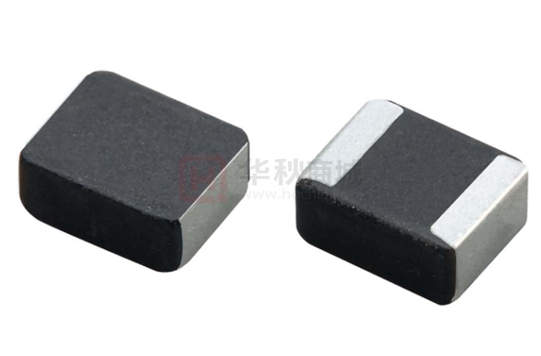


 工商网监
湘ICP备2023018690号
工商网监
湘ICP备2023018690号
