FTC201208-XXXM
REVISION:V1
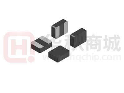
FTC201208 Series
This specification applies to FTC Series of Mini Molded Chip Power Inductor.
1
SPECIFICATION
1.2 APPLICATIONS
• Voltage Regulator Module (VRM)
• Multi-phase regulators
• Point-of-load modules
• Smart phone POL modules
• SSD modules
• Notebook regulators
• Battery power systems
• Graphics cards
• Data networking and storage systems
• DC/DC converter
• Cellular phones, LCD displays, HDDs
1.1 DESCRIPTION
• Halogen Free
• Thin type on- board power supply module for exchanger
1.3 ENVIRONMENTAL DATA
•Storage temperature range: -55°C to +125 °C
• 125 °C maximum total temperature
• Operating temperature range: -55°C to +125°C
operation
( ambient plus self- temperature rise)
• 2.2 x 1.4 x 1.0mm maximum
• Solder reflow temperature: J-STD-0 20 D compliant
surface mount package
• Magnetically shielded, low EMI
• High current carrying capacity, Low
core losses
• RoHS compliant
1.4 PRODUCT IDENTIFICATION
FTC
(1)
201208-1R0M
(2)
(3)
(4)
(1)Product Series
(2)Choke Size
(3)Initial Inductance(L @ 0A):1R0=1μH
(4)Inductance Tolerance:M=L+/-20%
Page 2 / 9
�FTC201208-XXXM
REVISION:V1
1.5 ELECTRICAL PARAMETERS
Part Number
L0
(μH)
±20%
IRMS IRMS ISAT
(Amp) (Amp) (Amp)
Max.
Typ.
Max.
ISAT
(Amp)
Typ.
DCR
DCR
(mΩ ) (mΩ )
Typ.
Max.
@25℃ @25℃
34
50
FTC201208-R47M
0.47±20%
2.7
2.97
4.6
5.52
FTC201208-1R0M
1±20%
2.4
2.64
3.5
4.2
55
70
FTC201208-2R2M
2.2±20%
1.5
1.65
2.3
2.76
160
185
Notes :
1.
Initial Inductance (L0 ) Test Parameters:1MHz, 1V,Idc=0.0A,+25℃
2.
Operating temperature range - 55 °C to + 125 °C
3.
IDC(A): DC current (A) that will cause an approximate ΔT of 40 °C
4 .
5.
ISAT(A):DC
current (A) that will cause L0 to drop approximately 30 %
The part temperature (ambient + temp rise) should not exceed 125 °C under worst case operating
conditions. Circuit design, component placement, PWB trace size and thickness, airflow and other cooling
provisions all affect the part temperature. Part temperature should be verified in the end application.
6 . The rated current as listed is either the saturation current or the heating current depending on which value
is lower.
Page 3 / 9
�FTC201208-XXXM
REVISION:V1
1.6 DIMENSION-mm
1.7 RECOMMENDED PCB LAYOUT
(unit:mm)
Notes :
1.
Tolerances are +/-0. 1millimeters unless stated otherwise
2 .
Dimensions of recommended PCB layout are reference only .
3.
Do not route traces nor place vias underneath the inductor. Proper layout is required.
Page 4 / 9
�FTC201208-XXXM
REVISION:V1
2.
Reliability Data
No.
Items
Requirements
Test Methods and Remarks
100 V DC between inductor coil and The
2.1
Insulation Resistance
≥ 100MΩ
middle of the top surface of the body for
60 seconds.
Dip pads in flux and dip in solder pot
2.2
2.3
Solderability
Resistance to Soldering
Heat
90% or more of electrode area shall
(96.5Sn/3.0Ag/0.5Cu) at (245±5) ℃ for
be coated by new solder.
(5±1) seconds.
No visible mechanical damage.
Inductance change: Within ± 10%
Dip pads in flux and dip in solder pot
(96.5Sn/3.0Ag/0.5Cu) at (260±5) ℃ for
( 10± 1) seconds.
Inductors shall be subjected to
2.4
Adhesion of terminal
electrode
2.5
High temperature
Strong bond between the pad and
the core, without come offPC
board.
No visible mechanical damage.
Inductance change: Within ± 10%
(260±5)℃ for (20±5) s Soldering in the
base whit 0.3mm solder. And then aplomb
electrode way plus tax 10 N for ( 10± 1)
seconds.
Temperature is (+85±2)℃ and keep
(96±2) hours.
2.6
Low temperature
No visible mechanical damage.
Inductance change: Within ± 10%
Temperature is (-40±2)℃ and keep
(96±2) hours.
Page 5 / 9
�FTC201208-XXXM
REVISION:V1
( Continue on the table)
No.
Items
Requirements
Test Methods and Remarks
The test sample shall be placed at (-40±3)℃
2.7
Thermal shock
No visible mechanical damage.
Inductance change: Within ± 10%
and
( 125±2)℃ for (30±3) min, different temperature
conversion time is 2~3 minutes.
The temperature
cycle shall be repeated 32 cycles.
Placed at room
temperature for 2 hours, within 48 hours of testing.
a :+20 ℃ (30~45) min →
b: -40 ℃
2.9
Temperatur
characteristic
Inductance change Pc-b,Pc-d:
Within ±20%
c: +20 ℃
Static Humidity
min
(30~45)
→
min →
d: + 125 ℃ (30~45) min →
e: +20 ℃ (30~45)
Pc -b
2.10
(30~45)
Lb Lc
100% ; Pc -d
min
Ld Lc
Lc
100%
Lc
Inductors shall be subjected to (93±3)%RH . at
No visible mechanical damage.
(60±2)℃ for (96±2) h . Placed at room temperature
Inductance change: Within ± 10%
for 2 hours, within 48 hours of testing.
Inductors shall be store at (85±2)℃ for ( 1000±24)
hours with Irms applied.
Placed at room temperature for 2 hours, within 48
2.11
Life
No visible mechanical damage.
Inductance change: Within ± 10%
hours of testing.
Note: If the surface temperature of the part over
125 ℃ when the current is loaded, the current need
to reduce until the surface temperature of the part less
than 125 ℃.
Page 6 / 9
�FTC201208-XXXM
REVISION:V1
3.
Package
3.1. Tape Dimension( Unit:mm)
W
A0
B0
D
D1
E
F
K0
P0
P2
P
T
8±0.3
1.85±0. 1
2.25±0.1
1.5±0. 1
1.0MIN
1.75±0.1
3.5±0. 1
1. 15±0. 1
4.0±0.3
2.0±0.3
4.0±0.3
0.25±0.05
3.2. Direction of feed( Unit:mm)
b
A
B
C
D
a
178
Typical
58
Typical
13
Typical
8.4
Typical
Blank portions
Chip cavity
c
Leader
3.3. Packing quantity
BOX
(PCS)
REEL
(PCS)
3,000
15,000
Carton
PCS
150,000
3.4. Peeling required
3.5. F force:10~130g;
3.6. Peeling speed:300mm/min±10%;
3.7. Peeling angle:165°~180°。
Page 7 / 9
�FTC201208-XXXM
REVISION:V1
4.
Environmental Protection Statement
Response to RoHS directive :Our products are RoHS compliance.
5. Recommended soldering profile
5.1.Applicable soldering process to the products is reflow soldering.
5.2. Soldering Materials
⑴ Solder:Sn-3.0Ag-0.5Cu
⑵Flux: Use rosin- based flux, but not strongly acidic flux ( with chlorine exceeding 0 . 2 wt% ) . Do not use
water-soluble flux.
5.3. Soldering Profile
5.4. Soldering Iron
Reworking with electric soldering iron must preheating at 150℃ for 1 minute is required, and do not directly
touch the core with the tip of the soldering iron. The reworking soldering conditions are as follows:
5.4.1 Temperature of soldering iron tip :350℃;
5.4.2. Soldering iron power output:≤30W;
5.4.3. Diameter of soldering iron end:≤ 1.0mm;
5.4.4. Soldering time :
很抱歉,暂时无法提供与“FTC201208-2R2M”相匹配的价格&库存,您可以联系我们找货
免费人工找货