Technical Data 4149
Effective November 2015
Supersedes March 2007
SD53
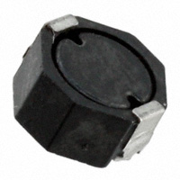
Low profile shielded power inductors
Applications
•
Desktop computers
•
Notebook and laptop regulators
•
LED and White LED drivers
•
Digital cameras, media devices
•
Battery power systems
Environmental Data
Product description
•
Octagonal shape utilizes board space
•
Shielded drum core
•
Inductance range from 1.1 uH to 100 uH
•
Current range from 0.44 A to 4.8 A
•
5.7 mm x 5.2 mm footprint surface mount
package in a 3.0 mm height
•
Ferrite core material
•
Halogen free, lead free, RoHS compliant
•
Storage temperature range (component):
-40 °C to +125 °C
•
Operating temperature range: -40 °C to +125 °C
(Ambient plus self temperature rise)
•
Solder reflow temperature: J-STD-020D
compliant
HALOGEN
Pb HF
FREE
�SD53
Low profile shielded power inductors
Technical Data 4149
Effective November 2015
Product Specifications
Part Number5
OCL1 (μH) ±20%
Part marking
Irms2
(A)
Isat3
(A)
DCR (Ω) typical
@ 20 °C
DCR (Ω) maximum @
20 °C
K-factor4
0.017
0.020
48
SD53-1R1-R
1.10
A
3.25
4.80
SD53-2R0-R
2.00
B
2.64
3.30
0.023
0.027
35
SD53-3R3-R
3.30
C
2.26
2.60
0.029
0.034
28
SD53-4R7-R
4.70
D
2.01
2.10
0.039
0.045
21
SD53-6R8-R
6.80
E
1.65
1.85
0.059
0.068
20
SD53-100-R
10.0
F
1.41
1.40
0.077
0.090
15
SD53-150-R
15.0
G
1.10
1.10
0.122
0.142
12
SD53-220-R
22.0
H
0.81
0.94
0.179
0.208
10
SD53-330-R
33.0
I
0.75
0.76
0.221
0.257
8
SD53-470-R
47.0
J
0.64
0.64
0.303
0.352
7
SD53-680-R
68.0
K
0.52
0.58
0.452
0.525
6
SD53-101-R
100
L
0.44
0.45
0.689
0.801
5
1. 1. Open Circuit Inductance (OCL) Test Parameters: 100 kHz, 0.1 Vrms, 0.0 Adc.
2. Irms: DC current for an approximate ∆T of 40 °C without core loss. Derating is necessary for AC currents. PCB layout,
trace thickness and width, air-flow, and proximity of other heat generating components will affect the temperature
rise. It is recommended that the temperature of the part not exceed 125 °C under worst case operating conditions
verified in the end application
3. lsat: Peak current for approximately 30% rolloff @ 25 °C.
4. K-factor: Used to determine B p-p for core loss (see graph). B p-p = K*L*∆I, B p-p(mT), K: (K factor from table),
L: (Inductance in uH), ∆I (Peak to peak ripple current in Amps).
5. Part Number Definition: SD53-xxx-R
SD53 = Product code and size; -xxx = Inductance value in uH; R = decimal point;
If no R is present then third character equals the number of zeros.
-R suffix = RoHS compliant.
53
Dimensions (mm)
Part Marking: Line 1: (1st digit= inductance value per Part Marking Designator); (2nd digit= Bi-weekly production date code); (3rd digit= Last
digit of the year produced), (4th digit= Internal manufacturing code). Line 2: 53=product size code)
Do not route traces or vias underneath the inductor
Packaging information (mm)
Parts packaged on 13” diameter reel, 2,600 parts per reel.
2
www.eaton.com/elx
�SD53
Low profile shielded power inductors
Technical Data 4149
Effective November 2015
Core loss vs. Bp-p
10
1
1MH z
Core Loss (W)
0.1
500kH z
300kH z
200kH z
100kH z
0.01
0.001
0.0001
0.00001
0.000001
1
10
Bp-p (mT)
100
1000
Temperature rise vs. total loss
Inductance characteristics
www.eaton.com/elx
3
�SD53
Low profile shielded power inductors
Technical Data 4149
Effective November 2015
Solder reflow profile
TP
TC -5°C
tP
Max. Ramp Up Rate = 3°C/s
Max. Ramp Down Rate = 6°C/s
Temperature
TL
Preheat
A
T smax
t
Table 1 - Standard SnPb Solder (Tc)
Package
Thickness
Volume
mm3
很抱歉,暂时无法提供与“SD53-4R7-R”相匹配的价格&库存,您可以联系我们找货
免费人工找货- 国内价格 香港价格
- 2600+8.763402600+1.09610
- 国内价格 香港价格
- 2600+10.826932600+1.35420
- 国内价格 香港价格
- 2600+9.728452600+1.21681
- 5200+9.176605200+1.14779
- 7800+9.171477800+1.14714
- 国内价格 香港价格
- 1+18.096121+2.26341
- 10+14.8411610+1.85629
- 100+12.20692100+1.52681
- 1000+11.225841000+1.40410
- 国内价格 香港价格
- 2600+6.700272600+0.83805
- 国内价格 香港价格
- 2600+9.584492600+1.19880
