承认书
APPROVAL SHEET
客户
CUSTOMER
华秋
客户料号
CUSTOMER P/N
规格描述
DESCRIPTION
产品编码
PART NUMBER
日期
DATE
8Ω/D11/F7.5/直脚/L20(8D-11)
MZ08011D1GA00
2023-04-24
呈昆承认栏
APPROVED BY CHENGKUN
批 准
APPROVED BY
姜白
审核
CHECK BY
制订
FORMULATE
BY
吴成爱
吴成爱
客户承认栏
APPROVED BY CUSTOMER
批 准
APPROVED BY
审核
CHECK BY
东莞市呈昆电子有限公司
DONGGUAN CITY CHENGKUN ELECTRONIC CO., LTD.
东莞市长安镇长青南路303号地王广场1102A
1102A Diwang square, No. 303, Changqing South Road, Chang'an Town, Dongguan City
PRC. TEL: +86-769-8533 5208
FAX: +86-769-8155 5989
Website: http://www.gdchengkun.com
�1、产品特点 Feature of Power Thermistor
1.1 应用范围 Appliaction
○转换电源,开关电源,UPS 电源 ○Switching power-supply,switch power,ups power
○镇流器及各类加热器
○Electronic energy saving lamps electronic ballast and all
kinds of electric heater
○各类显像管,显示器
○All kinds of RT,display
○电子节能灯,其他照明灯具
○Bulb and other lighting lamps
1.2 特点 Characteristic
○体积小,功率大,抑制浪涌电流能力强
○Small size,large power,strong capacity of
suppression of inrush current
○反应速度快
○材料常数(B 值)大,残余电阻小
○Fast resporse
○Big material constant(B value),small
residual resistance
○寿命长,可靠性高
○系列全,应用范围宽
○Long life and high reliability
○Complete series,wide applications
�2、技术参数 technical parameters
型号
Part No
R25
(Ω)
最大稳态电流
Max.steady
State current
(A)
残余电阻*
Residual
Resistance
(Ω)
5D‐5
5
1
0.35
8D‐5
8
0.7
0.77
10D‐5
10
0.7
0.77
20D‐5
20
0.5
0.997
33D‐5
33
0.5
1.88
5D‐7
5
2
0.28
8D‐7
8
1
0.77
10D‐7
10
1
0.77
12D‐7
12
1
0.82
16D‐7
16
0.7
1.00
20D‐7
20
0.6
1.11
22D‐7
22
0.6
1.11
33D‐7
33
0.5
1.49
3D‐9
3
4
0.12
5D‐9
5
3
0.21
6D‐9
6
2
0.32
8D‐9
8
2
0.40
10D‐9
10
2
0.46
12D‐9
12
1
0.66
15D‐9
15
1
0.80
耗散系数*
Dissipation
factor
(mw/℃)
热时间常数* 工作温度
Themal time Operating
Constant
Temperature
(s)
(℃)
约 6
约 20
‐40~+150
约 9
约 30
‐40~+150
约 11
约 35
‐40~+175
�型号
Part No
R25
(Ω)
最大稳态电流
Max.steady
State current
(A)
残余电阻*
Residual
Resistance
(Ω)
16D‐9
16
1
0.80
20D‐9
20
1
0.88
22D‐9
22
1
0.95
33D‐9
33
1
1.12
50D‐9
50
1
1.25
100D‐9
100
0.8
3.02
120D‐9
120
0.8
3.02
2.5D‐11
2.5
5
0.10
3D‐11
3
5
0.10
5D‐11
5
4
0.16
8D‐11
8
3
0.25
10D‐11
10
3
0.28
12D‐11
12
2
0.46
15D‐11
15
2
0.47
16D‐11
16
2
0.47
20D‐11
20
2
0.51
22D‐11
22
2
0.56
33D‐11
33
1.5
0.67
47D‐11
47
1.5
1.02
50D‐11
50
1.5
1.22
2.5D‐13
2.5
6
0.088
3D‐13
3
6
0.092
4.7D‐13
4.7
5
0.12
5D‐13
5
5
0.125
8D‐13
8
4
0.194
10D‐13
10
4
0.206
耗散系数*
Dissipation
factor
(mw/℃)
热时间常数* 工作温度
Themal time Operating
Constant
Temperature
(s)
(℃)
约 11
约 35
‐40~+175
约 14
约 50
‐40~+175
约 15
约 68
‐40~+200
�型号
Part No
R25
(Ω)
最大稳态电流
Max.steady
State current
(A)
残余电阻*
Residual
Resistance
(Ω)
16D‐13
16
3
0.335
18D‐13
18
3
0.372
20D‐13
20
3
0.372
30D‐13
30
2.5
0.517
47D‐13
47
2
0.81
1.5D‐15
1.5
8
0.071
2.5D‐15
2.5
8
0.071
3D‐15
3
7
0.075
5D‐15
5
6
0.112
7D‐15
7
5
0.173
8D‐15
8
5
0.178
10D‐15
10
5
0.18
15D‐15
15
4
0.268
16D‐15
16
4
0.268
18D‐15
18
4
0.288
20D‐15
20
4
0.288
30D‐15
30
3.5
0.438
47D‐15
47
3
0.68
50D‐15
50
3
0.72
1.3D‐20
1.3
9
0.037
1.5D‐20
1.5
9
0.037
2.5D‐20
2.5
8
0.055
3D‐20
3
8
0.055
5D‐20
5
7
0.087
8D‐20
8
6
0.142
10D‐20
10
6
0.162
16D‐20
16
5
0.212
20D‐20
20
5
0.212
耗散系数*
Dissipation
factor
(mw/℃)
热时间常数* 工作温度
Themal time Operating
Constant
Temperature
(s)
(℃)
约 15
约 68
‐40~+200
约 18
约 86
‐40~+200
约 24
约 113
‐40~+200
�3.1、一般参数(Common Parameters) :
引线图
产品尺寸
尺寸 Dim
(mm)
代号
Sym
Dmax
Tmax
型号 Part No
∅d
±0.05
F1
±1
F2
±1.5
直引线
Straight Lead
Wire
弯引线
Curved lead wire
L±1
L1±0.5
L2±2
NTC□D‐5
7
5
0.55
5
3
2.8‐20
2.8‐20
7 或 4
NTC□D‐7
9
5
0.55
5
3
2.8‐20
2.8‐20
7 或 4
NTC□D‐9
11
5.5
0.75/0.55
7.5/5
5/3
2.8‐20
2.8‐20
7 或 4
NTC□D‐11
13
5.5
0.75
7.5/5
5/3
2.8‐20
2.8‐20
7 或 4
NTC□D‐13
15.5
6
0.75
7.5
5
2.8‐20
2.8‐20
7 或 4
NTC□D‐15
17.5
6
0.75
10/7.5
5
2.8‐20
2.8‐20
7 或 4
NTC□D‐20
22.5
7
1.0
10/7.5
/
/
/
/
备注:□ 为额定零功率电阻值。
□Rated zero‐power resistance
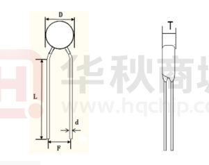
⑴ 引线形状 Lead the shape
⑵ 产品尺寸 Product size
型号
最大直径
Dmax
最大厚度
Tmax
引线直径
∅d±0.05mm
间距
引线长度
F±1mm
L1min
8D-11
13mm
6.0mm
0.75mm
7.5mm
20mm
�⑶ 材料 (Materials)
①、封装材料(Wrapper) :酚醛树脂(Modified phenolic resin)
②、引线(Down‐lead) :CP 线(CP Wire)
③、颜色(Coating color) :黑色(Black)
印字方式
NTC
8D‐11
NTC
负温度系数热敏电阻器 NTC thermistor
8
额定零功率电阻值 8 Ω
D
圆片型 Disk-Type
11
直径 10±1(mm)
3.2、主要技术参数(Parameters of Technology):
① 25℃时零功率电阻值(Ω)( Zero Power Resistance at 25℃)
:8±20%
② 热时间常数(S) (Thermal Time Constant)
:约 50
③ 热耗散系数(mW/℃)(Thermal Dissipation Constant )
:约 14
④ 工作温度(℃)(Operating Temperature)
:‐40 ~+175
⑤ 最大稳态电流(A)(Max Steady State Current)
:3
⑥ 最大允许使用容量值(240Vac) :
:470F
Maximum allowable capacity value (240Vac)
:470F
⑦ 绝缘电阻值 :>1000 MΩ,将热敏电阻的引出端连接起来作为一个电极,金属箔
作为另一个电极,在两电极间施加直流电压 100V±15V 测量两个电极间的绝缘电阻,
施加电压的时间为 1min,绝缘电阻不小于 1000 MΩ;
Insulation resistance: 1000 MΩ ohm, the terminal of the thermistor connected as an
electrode, metal foil as another electrode, 100V ± 15V DC voltage is applied between the
two electrodes measure the insulation resistance between the two electrodes, the voltage
applied to the time of 1min, the insulation resistance of not less than 1000 MΩ;
⑧ 耐电压 :将热敏电阻的引出端连接起来作为一个电极,金属箔作为另一个电极,
在两电极间施加一个频率为 40Hz-60Hz,取规定绝缘电压 1.4 倍的 AC 电压(AC500V)为
峰值电压,持续时间为 60s±5s,电压应近似于 100V∕s 的速率逐步施加,热敏电阻器
应无击穿或飞弧。
�High voltage terminal: thermistor connected as an electrode, metal foil as another
electrode in two electrode applied between a frequency of 40Hz-60Hz, AC voltage and
insulation voltage of 1.4 times the provisions (AC500V) for the duration of the peak voltage,
60s + 5S, the rate of voltage should be similar to the 100V / s thermistor applied gradually,
there should be no breakdown or arcing.
⑨ B 值(K)( B Value)
:2800±10%
用以下公式表示指数:Using the following formula
B =【( Ta × Tb )/( Tb – Ta )】 × In( Ra / Rb )
或者
B = 2.303 ×【( Ta × Tb )/( Tb – Ta )】×log( Ra / Rb )
公式中:
B--
常数(单位为 K)Constant (unit K)
Ra--
在温度 Ta(单位为 K)下测定的零功率电阻值(单位为Ω);
Rb--
在温度 Tb(单位为 K)下测定的零功率电阻值(单位为Ω)。
Ta=298.15K
Tb=358.15K
B 值是材料系数或指热敏指数,B 值的大小由材料特性决定,B 值允许±10%公差
范围,影响 B 值大小的因素属材料特性;B 值不同,残余电阻大小不同,持续工作时温
升也不同;B 值越大,残余电阻越小,工作时温升越小。
B value is the material coefficient or thermal index, B value is decided by the size of the
material properties, allowing the + 5% tolerance range of B value, B value influence the
size of the material properties; the B values are different, the residual resistance of
different sizes, continuous working temperature rise is also different; the bigger the B
value, the residual resistance is small when the temperature rise is small.
4、热敏电阻选用原则 Principle of thermal resistor is chosen
4.1 热敏电阻的最大工作电流>回路的工作电流
Thermistor maximum operating current> loop operating current
�4.2 热电阻的标称电阻值 R≥1.414*E/Im
Nominal resistance values of thermal resistance R≥1.414 * E / Im
E 为线路电压 E is the line voltage Im 为浪涌电流 Im a surge current 一般来讲
对于开关电源 转换电源 不间断电源 逆变电源等 Im=100 倍工作电流对于灯丝加
热器等的电路 Im=30 倍工作电流
In general, the switching power supply, switching power supplies, uninterruptible
power supplies, power inverter and other times operating current Im = 100For the
filament heater circuit like Im = 30 times the operating current.
4.3 B 值越大,残余电阻越小,工作时温升越小。
B The larger the value, the smaller the residual resistance, the smaller the
temperature rise during operation.
4.4 热时间常数和耗散系数两者为互为依赖的关系,并不是说某一个数值越大越好或越
小越好,而是两者的乘积越大说明热敏电阻的热容量就越大,那么抗浪涌电流的能力
就越强。
Thermal time constant and dissipation factor as both mutually dependent relationship, not
to say that one or the greater the value, the better the smaller the better, but the product
of the two greater the heat capacity of the thermistor greater, then resistance to surge
current, the stronger
4.5 热敏电阻用于电源电路时主要是用来抑制开机时的大浪涌电流,大的浪涌电流是电
容放电产生,所以电路中所要安装的滤波储能电容的选配也是很关键的一个条件,为
确保热敏电阻器能够安全的起到保护电路的作用,所以要求电源设计厂家也应该充分
考虑这一因素。
When the power supply circuit for the thermistor is mainly used to suppress large inrush
current at power‐on, a large inrush current is the capacitor discharge, the filter to be
installed in the tank circuit capacitance matching is a very critical condition to ensure that
�the thermistor circuit can play a role in security protection, so the power supply design
requirements for manufacturers should also take full account of this factor.
4.6 通过电路中的最大工作电压和最大启动电流等参数可以利用公式 R=U/I 计算出电阻
值范围。
Through the circuit maximum operating voltage and maximum starting current and other
parameters can use the formula R = U / I calculated the resistance value range.
4.7 以上这些选用原则可以锁定出 NTC 热敏电阻的对应型号,如果贵司有特殊设计需要
可与我司技术部洽谈。
These principles may choose to lock the NTC thermistor corresponding model, if your
company has special design needs with our technical department to discuss.
5、存储条件 Storage condition
5.1 存贮环境条件
温度 Temperature
湿度 Humidity
期限 Term
-10℃~+40℃
≤70%RH
≤1年 (先进先出 First-in/ First-out)
1.不要暴露在下列环境条件下,否则将导致性能衰退或
参数漂移
Do not exposing the components to the
following conditions, otherwise, it may result
in deterioration of characteristics
地点 Place
2.
腐 蚀 性 或 易 氧 化 气 体 Corrosive gas or
deoxidizing gas
3. 易燃易爆气体Flammable and explosive gases
4. 油、水和化学溶液Oil, water and chemical liquid
5. 太阳光下Under the sunlight
�5.2 请不要在下列条件下使用本元件,否则将可能导致性能衰退或产品损毁,甚至引起
火灾。
Do not apply the components under the following conditions, otherwise, it may result
in deterioration of characteristics,destruction of components orin the worst case,to
catching fire
5.2.1 超过最大的工作电流 Exceeding Imax
5.2.2 超过许可工作温度范围 Exceeding rated temperature range
5.2.3 散热不良,由于散热不良,本元件可能因部分过热而导致破坏
Inferior thermal dissipation,Due to badly inferior thermal dissipation, some part of
the components body will become overheated and then be damaged
6、产品性能 properties of products
6.1 机械性能 Mechanical Characteristics
机械性能 MECHANICAL CHARACTERISTICS
指标项目
Item
技术要求
Specification
可焊性 Solder-ability
浸润部分上锡均匀,上
锡面积≥95%
The terminals shall be
uniformly tinned, and its
area≥95%
将引出端沾助焊剂后,浸入到温度为240-245℃、深度为
15mm 的锡槽中锡面距NTC 本体下端6mm 处,持续2-3
秒。(参见IEC68-2-20 /GB2423.28 试验Ta)
Dipping the NTC terminals to a depth of 15mm in a soldering
bath of 240-245℃ and to the place of 6mm far from NTC
body for2-3s (See IEC68-2-20 /GB2423.28 Ta )
无可见损伤
No visible mechanical
damage.
ΔR/RN ≤20%
(ΔR =∣RN-RN'∣)
根据IEC68-2-20(GB2423 .28)试验Tb 进行试验。
采用焊槽法,将引出端沾助焊剂后,浸入到温度为265±
5℃、深度为15mm 的锡槽中,锡面距NTC 本体下端6mm
处,维持10±1 秒. 在25±2℃条件下恢复4-5h 后,复测
额定零功率电阻RN'.
Dipping the NTC terminals to a depth of 15mm in a soldering
bath of 265±5℃ and to the place for 6mm below from NTC
body for 10±1s.After recovering4-5h under 25±2℃. The
rated zero power resistance value RN' shall be measured.
(See IEC68-2-20 /GB2423.28 Tb)
无损坏
No break out
ΔR/RN ≤20%
(ΔR =∣RN-RN'∣)
根据IEC68-2-21(GB2423 .29)试验U 进行试验。
试验 Ua:拉力10N,持续10 S;
试验 Ub:弯曲90°,拉力5N,持续10 S;
扭转 180°,拉力5N,持续10 S。
在 25±2℃条件下恢复4~5 h 后,复测额定零功率电阻RN'
Fasten the body and apply a force gradually to each lead until
10N and then keep for 10sec, Hold body and apply a force to
each lead until 90°slowly at 5N in the direction of lead
axis and then keep for 10sec, and do this in the opposite
direction repeat for other terminal. After recovering 4~5h
under 25±2℃, the rated zero power resistance value RN' shall
be measured.
(See IEC68-2-21/GB2423.29 Ua / Ub)
耐焊接热Resistance To
Soldering Heat
引出端强度
Strength of lead terminal
测试条件/方法
Test Conditions & Methods
�6.2 电气性能 Electrical Characteristics
电气性能 ELECTRICAL CHARACTERISTICS
测试条件/方法 Test Conditions & Method
指标项目
Item
额定零功率电阻
Rated Zero-Power Resistance
RN (Ω)
热耗散系数δ(mW/℃)
Thermal Dissipation Constant
技术要求
Specification
8±20%
≈14
测试条件/方法
Test Conditions & Methods
环境温度 TA: 25℃±1℃
测试电压: 1.5VDC
在恒温TA 条件下,放置1~2 小时后测得阻值RN。
Ambient temp. Range:25℃±1℃(TA).
Testing voltage: 1.5VDC
After placing for 1~2 hours under TA, the
resistance value shall be measured
在特定的环境温度下,热耗散系数(δ)为热敏电阻电功率消耗
(ΔP)与本体温度变化量 (ΔT)的比值.
The thermal dissipation constant(δ) could be calculated by the
ratio of a change in power dissipation(ΔP) of the thermistor to a
change in temperature(ΔT) of the thermistor at a specified
ambient temperature
热时间常数(τ)为在零功率条件下,热敏电阻的温度下降到其
最初温度与最终温度之差为63.2% 时所需要的时间
热时间常数τ(s)
Thermal Time Constant
≈50
材料常数
Material Constant B
2800±10%
B=T1T2/( T2- T1) ×
Ln
(R1/R2)
R1 , R2 分别为 T1 , T2 温度下的零功率电阻
R1 , R2 is zero-power resistance at T1 , T2
T1 = 298.15 K(25℃) T2 = 323.15 K(50℃)
最大稳态电流(A)
Max.Steady State Current
无可见损伤
visible mechanical
damage.
ΔRN / RN ≤20%
(ΔR =∣RN-RN'∣)
环境温度:25℃±2℃Ambient temp. Range.
测试电流 3.0A Testing Current
The time(τ shall be measured within which the temperature
change of NTC thermistor is reached at 63.2% of the ambient
temperature change under zero power condition
�6.3 可靠性试验 Reliability Test
可靠性试验(周期性检测项目)Reliability Test
指标项目
Item
温度循环测试
Temp. Cycling Testing
电循环测试
Electrical Cycling Testing
持久性测试
LoadLife ( Endurance )
Testing
耐湿性测试
Humidity Testing
技术要求
Specification
测试条件/方法
Test Conditions & Methods
无可见损伤
No visible mechanical
damage.
ΔRN / RN ≤20%
(ΔR =∣RN-RN'∣)
在 Ta=-40±3℃和Tb=200±3℃的环境温度中
各存放30 分钟, 循环5 次.每次高低温循环都
有在25±2℃的环境中过渡5 分钟。样品进行
温度循环测试后,取出放置室温(25±2℃)
4~5 小时后测量零功率电阻RN'.
Ta:-40±3℃/ 30min→25±2℃/ 5min→ Tb:200
±3℃/ 30min→25±2℃/ 5min Cycles:
5times After recovering 4~5 h under 25±2℃,
the rated zero power resistance value RN' shall be
measured.
无可见损伤
No visible mechanical
damage.
ΔRN / RN ≤20%
(ΔR =∣RN-RN'∣)
环境温度:25℃±2℃.
循环次数: 1,000 次
通/断: 1 分钟 / 5 分钟
测试电流:3.0A
样品置于室温(25±2℃)4~5 小时后,测量其
零功率电阻RN'.
Ambient temp. Range:25℃±2℃.
Cycles: 1,000times On / Off: 1m / 5m
Test Current 3.0A
After recovering 4~5h under 25±2℃, the rated
zero power resistance value RN' shall be
measured.
无可见损伤
No visible mechanical
damage.
ΔRN / RN ≤20%
(ΔR =∣RN-RN'∣)
环境温度:25℃±2℃.样品通过最大工作电流
3.0A , 1,000±24 小时后,取出置于室温(25
±2℃)4~5 小时后,测量其零功率电阻RN'.
Ambient temp. Range:25℃±2℃; 3.0A/ 1,000
±24h After recovering 4~5 h under 25±2℃,
the ratedzero power resistance value RN' shall be
measured.
无可见损伤
No visible mechanical
damage.
ΔRN / RN ≤20%
(ΔR =∣RN-RN'∣)
在温度 40±2℃,相对湿度 93±3%的环境中
放置 1000±24 小时后,取出置于室温(25±
2℃)4~5 小时后, 测量其零功率电阻RN'.
Ambient temp. range : 40℃±2℃
R.H.:93±3% , Energized time:1000±24 h
After recovering 4~5 h under 25±2℃, the rated
zero power resistance value RN' shall be
measured
�7、电压-电流关系曲线 Graph of Voltage vs. Current
8、产品特性曲线 Graph of Characteristics
8.1 电阻-温度关系曲线 Graph of Resistance vs. Temperature
1000.00
Resistance (Ω)
100.00
10.00
1.00
0.10
0.01
-40 -30 -20 -10 0 10 20 30 40 50 60 70 80 90 100110120130140150160170180190200
Temperature (℃ )
�8.1.1 R‐T chart 阻温特性表
阻值 Resistance
温度
Temp℃
下限值
lower limiting
value
中心值
Central value
Ω
阻值 Resistance
上限值
upper-limit
温度
Temp℃
value
Ω
下限值
中心值
上限值
lower limiting
Central
upper-limit
value
value
value
-40.0
67.54
109.69
171.02
-19.0
27.65
40.66
57.41
-39.0
64.49
104.20
161.64
-18.0
26.59
38.94
54.75
-38.0
61.60
99.04
152.84
-17.0
25.59
37.31
52.23
-37.0
58.87
94.17
144.60
-16.0
24.63
35.76
49.84
-36.0
56.28
89.57
136.86
-15.0
23.71
34.28
47.58
-35.0
53.83
85.24
129.60
-14.0
22.83
32.88
45.44
-34.0
51.50
81.15
122.77
-13.0
22.00
31.54
43.41
-33.0
49.28
77.29
116.36
-12.0
21.20
30.27
41.49
-32.0
47.19
73.64
110.34
-11.0
20.43
29.05
39.66
-31.0
45.19
70.19
104.67
-10.0
19.70
27.90
37.93
-30.0
43.30
66.93
99.33
-9.0
19.00
26.80
36.29
-29.0
41.50
63.85
94.31
-8.0
18.32
25.75
34.72
-28.0
39.79
60.93
89.58
-7.0
17.68
24.74
33.24
-27.0
38.16
58.17
85.12
-6.0
17.07
23.79
31.83
-26.0
36.61
55.55
80.92
-5.0
16.48
22.88
30.49
-25.0
35.14
53.07
76.96
-4.0
15.91
22.01
29.22
-24.0
33.74
50.72
73.22
-3.0
15.37
21.17
28.01
-23.0
32.40
48.50
69.69
-2.0
14.85
20.38
26.85
-22.0
31.13
46.38
66.35
-1.0
14.35
19.62
25.76
-21.0
29.91
44.38
63.20
0.0
13.87
18.90
24.71
-20.0
28.75
42.47
60.23
1.0
13.41
18.20
23.72
�8.1.2
R-T
chart
阻温特性表
阻值 Resistance
下限值
温度 Temp℃
lower limiting
中心值
Central value
value
Ω
阻值 Resistance
上限值
upper-limit
value
温度
Temp℃
Ω
下限值
中心值
上限值
lower limiting
Central
upper-limit
value
value
value
2.0
12.97
17.54
22.77
23.0
6.78
8.52
10.29
3.0
12.55
16.91
21.86
24.0
6.58
8.26
9.94
4.0
12.14
16.30
21.00
25.0
6.40
8.00
9.60
5.0
11.75
15.72
20.18
26.0
6.18
7.75
9.33
6.0
11.38
15.16
19.39
27.0
5.97
7.51
9.07
7.0
11.02
14.63
18.64
28.0
5.77
7.29
8.82
8.0
10.67
14.12
17.93
29.0
5.58
7.06
8.58
9.0
10.34
13.63
17.25
30.0
5.40
6.85
8.35
10.0
10.01
13.16
16.59
31.0
5.22
6.65
8.13
11.0
9.71
12.71
15.97
32.0
5.05
6.45
7.91
12.0
9.41
12.28
15.37
33.0
4.89
6.26
7.70
13.0
9.12
11.86
14.81
34.0
4.73
6.08
7.49
14.0
8.85
11.46
14.26
35.0
4.58
5.90
7.30
15.0
8.58
11.08
13.74
36.0
4.43
5.73
7.11
16.0
8.33
10.72
13.24
37.0
4.29
5.56
6.92
17.0
8.08
10.36
12.76
38.0
4.16
5.40
6.74
18.0
7.84
10.03
12.31
39.0
4.03
5.25
6.57
19.0
7.61
9.70
11.87
40.0
3.90
5.10
6.40
20.0
7.39
9.39
11.45
41.0
3.78
4.96
6.24
21.0
7.18
9.09
11.05
42.0
3.67
4.82
6.09
22.0
6.97
8.80
10.66
43.0
3.55
4.69
5.93
�8.1.3
R-T
chart
阻温特性表
阻值 Resistance
下限值
温度 Temp℃
lower limiting
中心值
Central value
value
Ω
阻值 Resistance
上限值
upper-limit
value
温度
Temp℃
Ω
下限值
中心值
上限值
lower limiting
Central
upper-limit
value
value
value
44.0
3.45
4.56
5.79
65.0
1.89
2.63
3.53
45.0
3.34
4.43
5.64
66.0
1.84
2.57
3.46
46.0
3.24
4.31
5.50
67.0
1.79
2.51
3.38
47.0
3.15
4.20
5.37
68.0
1.74
2.45
3.31
48.0
3.05
4.08
5.24
69.0
1.70
2.39
3.24
49.0
2.96
3.97
5.11
70.0
1.65
2.33
3.17
50.0
2.88
3.87
4.99
71.0
1.61
2.28
3.10
51.0
2.79
3.77
4.87
72.0
1.57
2.23
3.04
52.0
2.71
3.67
4.76
73.0
1.53
2.18
2.97
53.0
2.64
3.57
4.65
74.0
1.49
2.13
2.91
54.0
2.56
3.48
4.54
75.0
1.45
2.08
2.85
55.0
2.49
3.39
4.43
76.0
1.42
2.03
2.79
56.0
2.42
3.30
4.33
77.0
1.38
1.98
2.74
57.0
2.35
3.22
4.23
78.0
1.35
1.94
2.68
58.0
2.29
3.14
4.13
79.0
1.31
1.90
2.63
59.0
2.22
3.06
4.04
80.0
1.28
1.85
2.57
60.0
2.16
2.98
3.95
81.0
1.25
1.81
2.52
61.0
2.10
2.91
3.86
82.0
1.22
1.77
2.47
62.0
2.05
2.84
3.78
83.0
1.19
1.73
2.42
63.0
1.99
2.77
3.69
84.0
1.16
1.70
2.38
64.0
1.94
2.70
3.61
85.0
1.13
1.66
2.33
�8.1.4 R-T
chart
阻温特性表
阻值 Resistance
下限值
温度 Temp℃
lower limiting
中心值
Central value
value
Ω
阻值 Resistance
上限值
Ω
下限值
中心值
上限值
upper-limit
温度
lower limiting
Central
upper-limit
value
Temp℃
value
value
value
86.0
1.11
1.62
2.28
108.0
0.67
1.03
1.52
87.0
1.08
1.59
2.24
109.0
0.66
1.02
1.50
88.0
1.06
1.55
2.20
110.0
0.65
1.00
1.47
89.0
1.03
1.52
2.16
111.0
0.63
0.98
1.45
90.0
1.01
1.49
2.11
112.0
0.62
0.96
1.42
91.0
0.98
1.46
2.07
113.0
0.61
0.94
1.40
92.0
0.96
1.43
2.04
114.0
0.60
0.92
1.38
93.0
0.94
1.40
2.00
115.0
0.58
0.91
1.35
94.0
0.92
1.37
1.96
116.0
0.57
0.89
1.33
95.0
0.90
1.34
1.92
117.0
0.56
0.87
1.31
96.0
0.88
1.31
1.89
118.0
0.55
0.86
1.29
97.0
0.86
1.29
1.85
119.0
0.54
0.84
1.27
98.0
0.84
1.26
1.82
120.0
0.53
0.83
1.25
99.0
0.82
1.24
1.79
121.0
0.52
0.81
1.23
100.0
0.80
1.21
1.76
122.0
0.51
0.80
1.21
101.0
0.78
1.19
1.72
123.0
0.50
0.78
1.19
102.0
0.77
1.16
1.69
124.0
0.49
0.77
1.17
103.0
0.75
1.14
1.66
125.0
0.48
0.76
1.15
104.0
0.74
1.12
1.63
126.0
0.47
0.74
1.13
105.0
0.72
1.10
1.61
127.0
0.46
0.73
1.11
106.0
0.70
1.08
1.58
128.0
0.45
0.72
1.10
107.0
0.69
1.06
1.55
129.0
0.44
0.71
1.08
�8.1.5
R-T
chart
阻温特性表
阻值 Resistance
下限值
温度 Temp℃
lower limiting
value
中心值
Central value
Ω
阻值 Resistance
上限值
upper-limit
value
温度
Temp℃
Ω
下限值
中心值
上限值
lower limiting
Central
upper-limit
value
value
value
130.0
0.43
0.69
1.06
153.0
0.29
0.48
0.76
131.0
0.43
0.68
1.05
154.0
0.28
0.47
0.75
132.0
0.42
0.67
1.03
155.0
0.28
0.46
0.74
133.0
0.41
0.66
1.01
156.0
0.27
0.46
0.73
134.0
0.40
0.65
1.00
157.0
0.27
0.45
0.72
135.0
0.40
0.64
0.98
158.0
0.26
0.44
0.71
136.0
0.39
0.63
0.97
159.0
0.26
0.43
0.70
137.0
0.38
0.62
0.95
160.0
0.26
0.43
0.69
138.0
0.37
0.61
0.94
161.0
0.25
0.42
0.68
139.0
0.37
0.60
0.93
162.0
0.25
0.42
0.67
140.0
0.36
0.59
0.91
163.0
0.24
0.41
0.66
141.0
0.35
0.58
0.90
164.0
0.24
0.40
0.65
142.0
0.35
0.57
0.89
165.0
0.24
0.40
0.64
143.0
0.34
0.56
0.87
166.0
0.23
0.39
0.64
144.0
0.34
0.55
0.86
167.0
0.23
0.39
0.63
145.0
0.33
0.54
0.85
168.0
0.22
0.38
0.62
146.0
0.32
0.53
0.84
169.0
0.22
0.38
0.61
147.0
0.32
0.52
0.82
170.0
0.22
0.37
0.60
148.0
0.31
0.52
0.81
171.0
0.21
0.37
0.60
149.0
0.31
0.51
0.80
172.0
0.21
0.36
0.59
150.0
0.30
0.50
0.79
173.0
0.21
0.35
0.58
151.0
0.30
0.49
0.78
174.0
0.20
0.35
0.57
152.0
0.29
0.48
0.77
175.0
0.20
0.35
0.57
�9 NTC热敏电阻注意事项 Matters Needing Attention For NTC Thermistors
请遵循以下事项,否则可能会造成 NTC 热敏电阻损坏,使用设备损伤或引起误动作等后果
PleasefollowtheruleslistedbelowwhenusingNTCthermistors.Otherwise,youmay
causedamagetotheNTCthermistorandrelevantequipmentorhurtyourself.
① 、请勿在使用温度范围以外使用,请勿施加超出使用温度范围上下限的急剧温度变化。
Do not use the thermistor under temperature beyond the operating temperature range.
Do not apply rapid temperature changes which exceed the upper and lower limits of the
operating temperature range.
②、请在额定功率条件下使用 NTC 热敏电阻。各规格最大额定功率为Φ5-0.7W Φ7—1.2W
Φ9—1.9W Φ11—2.3W Φ13—3W Φ15—3.5W Φ20—4W
Please use the NTC thermistor under the standard power. The maximum standard powers of
each specification are :Φ5-0.7W Φ7—1.2W Φ9—1.9W Φ11—2.3W Φ13—3W Φ15—3.5W
Φ20—4W
③、在高湿高温环境下使用护套型 NTC 热敏电阻时应采取仅使护套封闭部分暴露于环境(水中 湿
气)中,而护套开口部分不会直接接触到水及蒸汽的设计
When using the sheath type NTC thermistors in the high humidity and high temperature
environment, the sealing part of the sheath should be exposed to the environment (moisture
or water) while the opening part of the sheath is not directly exposed to the water or steam.
④、配线时应确保导线端部(含连接器)不会深入水.蒸汽.电解质液等否则会造成接触不良。
When wiring, the ends of the wire (including connectors) should not be posited deeply
inside water, steam. electrolyte solution, etc. Otherwise, it will result in poor contact.
⑤、请勿在腐蚀性气体的环境(Cl2 .NH3 .SOx.NOx)以及会接触到电解质液.盐水.酸.碱.有机溶
剂的场所中使用。
Please do not expose the thermistor to corrosive gas (NH3, SOx, NOx, Cl2) or any saline
solution, acid solution, alkaline solution and electrolyte solution.
⑥、请勿过度拉伸及弯曲导线,请勿施加过度的振动.冲击及压力
Do not over stretch or bend the wire. Please do not apply excessive vibration, pressure
and impact on the thermistor.
⑦、金属腐蚀可能会造成设备功能故障,故在选择材质时应确保金属护套型及螺钉紧固型 NTC
热敏电阻与安装的金属件之间不会产生接触的电位差。
To avoid equipment faults caused by metal corrosion, please choose the right material
to make sure there is no potential difference at the contact point between metal sheath type
or screw fastening type NTC thermistor and the metal components.
⑧、功率型 NTC 周围应避免安装发热和易燃元件,建议选用弯脚上部引线较高的产品,使 NTC
热敏电阻在线路板上高出其它元件,以免发热影响其它元件正常工作。
Do not install any flammable component or component generating heat surrounding the
power type NTC.
Our recommendation is to avoid the negative effect brought by the heat from the NTC,
please use products with higher lead wire on the bending feet to make the NTC thermistor
on the circuit board higher than the other components.
�