FR9205F
18V, 2A Synchronous Step-Down
85T
DC/DC Converter
Description
Features
The FR9205F is a synchronous step-down DC/DC
converter with fast constant on time (FCOT) mode
control. The device provides 4.5V to 18V input
voltage range and 2A continuous load current
capability. It is constant on time pulse width
modulation (PWM) controller that supports FCOT
mode control. Operation frequency depends on Input
and output voltage condition.
The
FR9205F
fault
protection
includes
cycle-by-cycle current limit, short circuit protection,
UVLO and thermal shutdown. The soft-start function
prevents inrush current at turn-on. The FR9205F use
fast constant on time control that provides fast
transient response, the noise immunity and all kinds
of very low ESR output capacitor for ensuring
performance stabilization.
The FR9205F is offered in SOT-23-6 package, which
provides good thermal conductance.
Low RDS(ON) Integrated Power MOSFET
(145mΩ/90mΩ)
Wide Input Voltage Range: 4.5V to 18V
Output Voltage Range: 0.765V to 8V
2A Output Current
FCOT Mode Enables Fast Transient Response
Pseudo 850kHz Frequency
Input Under Voltage Lockout
Internal 1.5ms Soft-Start
Cycle-by-Cycle Current Limit
Hiccup Short Circuit Protection
Over Temperature Protection with Auto Recovery
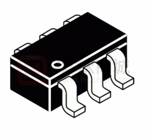
SOT-23-6 Package
Applications
STB (Set-Top-Box)
LCD Display, TV
Distributed Power System
Networking, XDSL Modem
Pin Assignments
Ordering Information
S6 Package (SOT-23-6)
FR9205F□
BST SHDN FB
6
1
Package Type
S6: SOT-23-6
4
5
(Marking)
2
3
GND LX VIN
SOT-23-6 Marking
Figure 1. Pin Assignments of FR9205F
FR9205F-Preliminary 0.2-FEB-2020
Part Number
Product Code
FR9205FS6
GE1
1
�FR9205F
85T
Typical Application Circuit
C3
0.1μF
R3
100kΩ
SHDN
L1
4.7μH
LX
VIN
VIN
BST
R4
0Ω
VOUT
3.3V
4.5V to 18V
FR9205F
C1
22μF/25V
R1
33.2kΩ 1%
C4
82pF
C2
22μF/6.3V
FB
C5
0.1μF/50V
GND
R2
10kΩ 1%
Figure 2. FR9205F Application Circuit
VIN=12V, the recommended BOM list is as below.
VOUT
C1
R1
R2
C4
L1
C2
1.05V
22μF MLCC
3.74kΩ
10kΩ
68pF~220pF
2.2μH
22μF MLCC
1.2V
22μF MLCC
5.76kΩ
10kΩ
68pF~220pF
2.2μH
22μF MLCC
1.8V
22μF MLCC
13.7kΩ
10kΩ
68pF~220pF
2.2μH
22μF MLCC
2.5V
22μF MLCC
22.6kΩ
10kΩ
68pF~220pF
3.3μH
22μF MLCC
3.3V
22μF MLCC
33.2kΩ
10kΩ
68pF~220pF
4.7μH
22μF MLCC
5V
22μF MLCC
54.9kΩ
10kΩ
68pF~220pF
4.7μH
22μF MLCC
Table 1. Recommended Component Values
FR9205F-Preliminary 0.2-FEB-2020
2
�FR9205F
85T
Functional Pin Description
Pin Name
Pin No.
GND
1
Ground pin.
LX
2
Power switching node. Connect an external inductor to this switching node.
VIN
3
Power supply input pin. Placed input capacitors as close as possible from VIN to GND to avoid noise
influence.
FB
4
Voltage feedback input pin. Connect FB and VOUT with a resistive voltage divider. This IC senses
feedback voltage via FB and regulates it at 0.765V.
5
Enable input pin. Pull high to turn on IC, and pull low to turn off IC. Connect VIN with a 100kΩ resistor for
self-startup.
6
High side gate drive boost pin. A capacitor rating between 0.1uF~1uF must be connected from this pin to
LX. It can boost the gate drive to fully turn on the internal high side NMOS.
BST
Pin Function
Block Diagram
VIN
UVLO
&
POR
SHDN
OTP
Internal
Regulator
VCC
VCC
1M
Off Time
Generator
BST
High-Side
MOSFET
FB
Internal
Soft Start
On Time
Generator
OTP
Vref
Logic
Control
Driver
Logic
LX
UVLO
LX
OCP
Low-Side
MOSFET
Cycle by Cycle
Current Limit
GND
Figure 3. Block Diagram of FR9205F
FR9205F-Preliminary 0.2-FEB-2020
3
�Absolute Maximum Ratings (Note 1)
FR9205F
85T
● Supply Voltage VIN ------------------------------------------------------------------------------------------- -0.3V to +20V
● Enable Voltage
H
------------------------------------------------------------------------------------- -0.3V to +20V
● LX Voltage VLX ------------------------------------------------------------------------------------------------ -0.3 to (VIN +0.3V)
● Dynamic LX Voltage in 15ns Duration------------------------------------------------------------------- -5V to VIN +5V
● BST Pin Voltage VBST --------------------------------------------------------------------------------------- -0.3V to VLX +6.5V
● All Other Pins Voltage -------------------------------------------------------------------------------------- -0.3V to +6V
● Maximum Junction Temperature (TJ) ------------------------------------------------------------------- +150°C
● Storage Temperature (TS) --------------------------------------------------------------------------------- -65°C to +150°C
● Lead Temperature (Soldering, 10sec.) ----------------------------------------------------------------- +260°C
● Package Thermal Resistance, (θJA)
(Note 2)
SOT-23-6 ------------------------------------------------------------------------------------------ 250°C/W
● Package Thermal Resistance, (θJC)
SOT-23-6 --------------------------------------------------------------------------------------- --- 110°C/W
Note 1: Stresses beyond this listed under “Absolute Maximum Ratings" may cause permanent damage to the device.
Note 2: θJA is measured at 25°C ambient with the component mounted on a high effective thermal conductivity 4-layer
board of JEDEC-51-7. The thermal resistance greatly varies with layout, copper thickness, number of layers and PCB size.
Recommended Operating Conditions
● Supply Voltage VIN ------------------------------------------------------------------------------------------ +4.5V to +18V
● Operation Temperature Range --------------------------------------------------------------------------- -40°C to +85°C
FR9205F-Preliminary 0.2-FEB-2020
4
�FR9205F
85T
Electrical Characteristics
(VIN=12V, TA=25°C, unless otherwise specified.)
Parameter
Symbol
Conditions
Min
=2V, VFB=1V
VIN Quiescent Current
IDDQ
H
VIN Shutdown Supply Current
ISD
H
Feedback Voltage
VFB
4.5V≦VIN≦17V
Feedback Input Current
IFB
VFB=1V
Typ
Max
0.3
=0V
0.753
Unit
mA
1
10
μA
0.765
0.776
V
0.01
0.1
μA
High-Side MOSFET RDS(ON)
RDS(ON)
145
mΩ
Low-Side MOSFET RDS(ON)
RDS(ON)
90
mΩ
ILIMIT
3
A
VIN=12V, VOUT=1.05V
130
ns
Valley Current Limit
(Note 3)
On Time
TON
Minimum Off Time
TOFF(MIN)
VFB=0.4V
200
ns
Input Supply Voltage UVLO Threshold
VUVLO(Vth)
VIN Rising
4
V
UVLO Threshold Hysteresis
VUVLO(HYS)
0.35
V
TSS
1.5
ms
Internal Soft-Start Period
(Note 3)
H
Input Low Voltage
H
Input High Voltage
H
Input Current
Thermal Shutdown Threshold
Thermal Shutdown Hysteresis
H
(L
H
(H
(Note 3)
1.5
V
V
2
μA
TSD
160
°C
THYS
30
°C
H
(Note 3)
0.5
H
=2V
Note 3: Not production tested.
FR9205F-Preliminary 0.2-FEB-2020
5
�FR9205F
85T
Typical Performance Curves
VOUT=3.3V
100
100
90
90
80
80
Efficiency (%)
Efficiency (%)
VOUT=1.05V
70
60
50
40
30
VIN=5V
VIN=12V
VIN=18V
20
10
0
0.01
0.1
1
70
60
50
40
30
VIN=5V
VIN=12V
VIN=18V
20
10
0
0.01
10
0.1
Load Current (A)
Figure 4. Efficiency vs. Load Current
V
=2V, VFB=1V
300
Quiescent Current (μA)
100
90
80
Efficiency (%)
10
Figure 5. Efficiency vs. Load Current
VOUT=5V
70
60
50
40
30
VIN=12V
20
VIN=18V
10
280
260
240
220
200
180
160
0
0.01
0.1
1
-40 -30 -20 -10 0
10
10 20 30 40 50 60 70 80 90
Ambient Temperature (℃)
Load Current (A)
Figure 6. Efficiency vs. Load Current
Figure 7. Quiescent current vs. Input Voltage
VIN=12V, VOUT=3.3V, IOUT=0 to 2A
VIN=12V, IOUT=0A
0.770
950
Feedback Voltage (V)
Switching frequency (kHz)
1
Load Current (A)
930
910
890
870
850
830
810
790
770
0.768
0.766
0.764
0.762
0.760
0.758
0.756
0.754
0.752
0.750
750
0
0.2
0.4
0.6
0.8
1
1.2
1.4
1.6
1.8
Load Current (A)
Figure 8. Switch Frequency vs. Load Current
FR9205F-Preliminary 0.2-FEB-2020
2
-40 -30 -20 -10 0
10 20 30 40 50 60 70 80 90
Ambient Temperature (℃)
Figure 9. Feedback voltage vs. Temperature
6
�FR9205F
85T
Typical Performance Curves (Continued)
VIN=12V, VOUT=3.3V, C1=22μF, C2=22μF, C4=82pF, L1=4.7μH, TA=+25°C, unless otherwise noted.
IOUT=0A
IOUT=2A
VLX 5V/div.
VLX 5V/div.
VOUT 20mV/div.
VOUT 20mV/div.
IL
IL
1A/div.
1A/div.
2μs/div.
2μs/div.
Figure 10. Steady State Waveform
Figure 11. Steady State Waveform
IOUT=0A
IOUT=2A
VIN
5V/div.
VIN
5V/div.
VLX 5V/div.
VLX
5V/div.
VOUT 2V/div.
VOUT 2V/div.
IL
1A/div.
IL
4ms/div.
1A/div.
4ms/div.
Figure 12. Startup Through Power Supply Waveform
IOUT=0A
Figure 13. Startup Through Power Supply Waveform
IOUT=2A
VIN
5V/div.
VIN
VLX
5V/div.
VLX 5V/div.
VOUT 2V/div.
VOUT 2V/div.
IL
1A/div.
40m/div.
Figure 14. Shutdown Through Power Supply Waveform
FR9205F-Preliminary 0.2-FEB-2020
IL
5V/div.
1A/div.
40ms/div.
Figure 15. Shutdown Through Power Supply Waveform
7
�FR9205F
85T
Typical Performance Curves (Continued)
VIN=12V, VOUT=3.3V, C1=22μF, C2=22μF, C4=82pF, L1=4.7μH, TA=+25°C, unless otherwise noted.
IOUT=0A
IOUT=2A
2V/div.
2V/div.
VLX
5V/div.
VOUT
2V/div.
IL
1A/div.
VLX
5V/div.
VOUT
2V/div.
IL
4ms/div.
Figure 16. Startup Through
1A/div.
4ms/div.
H
Waveform
IOUT=0A
Figure 17. Startup Through
H
Waveform
IOUT=2A
2V/div.
2V/div.
VLX
VLX
5V/div.
VOUT 2V/div.
VOUT 2V/div.
IL
Figure 18. Shutdown Through
IL
1A/div.
4ms/div.
5V/div.
1A/div.
80μs/div.
H
Waveform
Figure 19. Shutdown Through
H
Waveform
IOUT=0A to 2A
VOUT
IL
100mV/div.
1A/div.
200μs /div.
Figure 20. Load Transient Waveform
FR9205F-Preliminary 0.2-FEB-2020
8
�FR9205F
85T
Function Description
The FR9205F is a synchronous step-down DC/DC
converter with fast constant on time (FCOT) mode
control. It has integrated high-side (145mΩ, typ and
low-side (90mΩ, typ) power switches, and provides
2A continuous load current. It regulates input voltage
from 4.5V to 18V, and down to an output voltage as
low as 0.765V. Using FCOT control scheme provides
fast transient response, which can minimize the
component size without additional external
compensation network.
Over Current Protection
Enable
Short Circuit Protection
The FR9205F H
pin provides digital control to
turn on/turn off the regulator. When the voltage of
H
exceeds the threshold voltage, the regulator
starts the soft start function. If the H
pin
voltage is below than the shutdown threshold
voltage, the regulator will turn into the shutdown
mode and the shutdown current will be smaller than
1μA. For auto start-up operation, connect H
to
VIN through a 100kΩ resistor.
The FR9205F provides short circuit protection
function to prevent the device damage from short
condition. When the short condition occurs and the
feedback voltage drops lower than 0.33V, the
oscillator frequency will be reduced naturally and
hiccup mode will be triggered to prevent the inductor
current increasing beyond the current limit. Once the
short condition is removed, the frequency will return
to normal.
Soft Start
The FR9205F employs internal soft start function to
reduce input inrush current during start up. The
typical value of internal soft start time is 1.5ms.
Input Under Voltage Lockout
When the FR9205F is power on, the internal circuits
are held inactive until VIN voltage exceeds the input
UVLO threshold voltage. And the regulator will be
disabled when VIN is below the input UVLO
threshold voltage. The hysteretic of the UVLO
comparator is 350mV (typ).
FR9205F-Preliminary 0.2-FEB-2020
The FR9205F over current protection function is
implemented using cycle-by-cycle current limit
architecture. The inductor current is monitored by
Low-side MOSFET. When the load current
increases, the inductor current also increases.
When the valley inductor current reaches the current
limit threshold, the output voltage starts to drop.
When the over current condition is removed, the
output voltage returns to the regulated value.
Over Temperature Protection
The FR9205F incorporates an over temperature
protection circuit to protect itself from overheating.
When the junction temperature exceeds the thermal
shutdown threshold temperature, the regulator will
be shutdown. And the hysteretic of the over
temperature protection is 30°C (typ).
9
�FR9205F
85T
Application Information
Output Voltage Setting
The output voltage VOUT is set using a resistive
divider from the output to FB. The FB pin regulated
voltage is 0.765V. Thus the output voltage equation
is:
.
T
1
R1
R2
Output Capacitor Selection
Table 2 lists recommended values of R1 and R2 for
most used output voltage.
Table 2 Recommended Resistance Values
VOUT
R1
A low ESR capacitor is required to keep the noise
minimum. Ceramic capacitors are better, but
tantalum or low ESR electrolytic capacitors may also
suffice. When using tantalum or electrolytic
capacitors, a 0.1μF ceramic capacitor should be
placed as close to the IC as possible.
The output capacitor is used to keep the DC output
voltage and supply the load transient current.
When operating in constant current mode, the
output ripple is determined by four components:
R2
5V
54.9kΩ
10kΩ
3.3V
33.2kΩ
10kΩ
2.5V
22.6kΩ
10kΩ
1.8V
13.7kΩ
10kΩ
1.2V
5.76kΩ
10kΩ
1.05V
3.74kΩ
10kΩ
R PPL
t
R PPL
R PPL (
C
t
L
R PPL
t
R
t
t
The following figures show the form of the ripple
contributions.
VRIPPLE(ESR)(t)
Place resistors R1 and R2 close to FB pin to prevent
stray pickup.
Input Capacitor Selection
The use of the input capacitor is filtering the input
voltage ripple and the MOSFETS switching spike
voltage. Because the input current to the step-down
converter is discontinuous, the input capacitor is
required to supply the current to the converter to
keep the DC input voltage. The capacitor voltage
rating should be 1.25 to 1.5 times greater than the
maximum input voltage. The input capacitor ripple
current RMS value is calculated as:
C
(RM
1
T
T
Where D is the duty cycle of the power MOSFET.
This function reaches the maximum value at D=0.5
and the equivalent RMS current is equal to IOUT/2.
The
following
diagram
is
the
graphical
representation of above equation.
+
VRIPPLE(ESL) (t)
(t)
+
VRIPPLE(C) (t)
(t)
+
VNOISE (t)
(t)
=
VRIPPLE(t)
1.25
ICIN(RMS) (A)
1
0.75
0.5
2A
1.5A
1A
(t)
0.25
0
10 20 30 40 50 60 70 80 90
D (%)
FR9205F-Preliminary 0.2-FEB-2020
10
�FR9205F
85T
Application Information (Continued)
R PPL (
R
R PPL (
L
T
F
C
T
1
L
R
L
R PPL (C
That will lower ripple current and result in lower
output ripple voltage. The Δ L is inductor
peak-to-peak ripple current:
L
L
T
F
C
2
L C
1
T
F
C
T
1
L
T
T
Where FOSC is the switching frequency, L is the
inductance value, VIN is the input voltage, ESR is the
equivalent series resistance value of the output
capacitor, ESL is the equivalent series inductance
value of the output capacitor and the COUT is the
output capacitor.
Low ESR capacitors are preferred to use.
Ceramic, tantalum or low ESR electrolytic capacitors
can be used depending on the output ripple
requirement. When using the ceramic capacitors,
the ESL component is usually negligible.
It is important to use the proper method to eliminate
high frequency noise when measuring the output
ripple. The figure shows how to locate the probe
across the capacitor when measuring output ripple.
Removing the scope probe plastic jacket in order to
expose the ground at the tip of the probe. It gives a
very short connection from the probe ground to the
capacitor and eliminating noise.
A good compromise value between size and
efficiency is to set the peak-to-peak inductor ripple
current Δ L equal to 30% of the maximum load
current. But setting the peak-to-peak inductor ripple
current Δ L between 20%~50% of the maximum load
current is also acceptable. Then the inductance can
be calculated with the following equation:
L
T(MA
T
L
F
T
C
L
External Diode Selection
For 5V input applications, it is recommended to add
an external boost diode. This helps improving the
efficiency. The boost diode can be a low cost one
such as 1N4148.
D1
1N4148
VIN
5V
Probe Ground
.
VIN
BST
FR9205F
C3
LX
VOUT
GND
Ceramic Capacitor
Inductor Selection
The output inductor is used for storing energy and
filtering output ripple current. But the trade-off
condition often happens between maximum energy
storage and the physical size of the inductor. The
first consideration for selecting the output inductor is
to make sure that the inductance is large enough to
keep the converter in the continuous current mode.
FR9205F-Preliminary 0.2-FEB-2020
11
�FR9205F
85T
Outline Information
SOT-23-6 Package (Unit: mm)
SYMBOLS
UNIT
DIMENSION IN MILLIMETER
MIN
MAX
A
0.90
1.45
A1
0.00
0.15
A2
0.90
1.30
B
0.30
0.50
D
2.80
3.00
E
2.60
3.00
E1
1.50
1.70
e
0.90
1.00
e1
1.80
2.00
L
0.30
0.60
Note: Followed From JEDEC MO-178-C.
Carrier Dimensions
Life Support Policy
Fitipower’s products are not authorized for use as critical components in life support devices or other medical systems.
FR9205F-Preliminary 0.2-FEB-2020
12
�