SURFACE MOUNT CERMET TRIMMERS (SINGLE TURN)
RoHS compliant
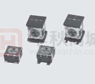
ST-32
INTERNAL STRUCTURE
2
1
7
6
5
3
4
9 8
Part name
Material
■ FEATURES
1
Wiper
Multi metal alloy
O�RoHS compliant
O�Rotor with a cross slot for ease of adjustment
O� Leaded terminals provide strong as adhesive strength
against P.C.B. bending
O�J-hook, Gull wing and leaded terminal configurations
O�Sealed (Washable: Refer to page 750.)
2
Cover
Stainless steel (SUS 304)
3
Housing
4
Terminal pin
Copper alloy, Sn-Cu-plated
5
Base element
Ceramic
6
“O” ring
7
Rotor
8
Electrode
Ag-Pd cermet
9
Resistive element
RuO2 cermet
Flammability
—
Epoxy
UL94V-0
—
Silicone rubber
UL94HB
Polyphenylenesulphide
UL94V-0
—
■ PART NUMBER DESIGNATION
S T - 3 2 E T A 1 0 0 Ω ( 1 2 )
Series name
Resistance code
Terminal pin
Resistance value
E:Sn-Cu (Lead-free)
Form of packaging
Product shape (Shape of terminal)
T:Taping (Reel)
Blank:Bulk in plastic bag
A, G:J-hook
B, H:Gull wing
※Please refer to the LIST OF PART NUMBERS when placing orders.
�ST-32
SURFACE MOUNT TRIMMERS
■ LIST OF PART NUMBERS
Adjustment
position
Shape of
terminal
〈Nominal resistance values〉
Form of packaging
Taping (reel)
Plastic bag
Top
adjustment
A (J-hook)
ST-32ETA
ST-32EA
B (Gull wing)
ST-32ETB
ST-32EB
Side
adjustment
G (J-hook)
ST-32ETG
ST-32EG
H (Gull wing)
ST-32ETH
ST-32EH
500 pcs./reel
100 pcs./pack
Pieces in package
■ ELECTRICAL CHARACTERISTICS
Nominal resistance range
A 10 Ω
A 20 Ω
50 Ω
100 Ω
200 Ω
300 Ω
500 Ω
1 kΩ
2 kΩ
3 kΩ
5 kΩ
10 kΩ
20 kΩ
30 kΩ
50 kΩ
100 kΩ
200 kΩ
500 kΩ
1 MΩ
2 MΩ
Fig.1
The products indicated by A mark are manufactured upon receipt of order basis.
※The part numbers on the left are all available with the respective combination of
(Fig. 1).
※Verify the above part numbers when placing orders.
※Taping specification is not sold separately and must be purchased in reel units.
■ MECHANICAL CHARACTERISTICS
10 Ω ~ 2 MΩ
Mechanical angle
250 ° (1 turn)
± 20 %
Operating torque
5 mN·m {51 gf·cm} maximum
Resistance tolerance
Power ratings
0.125 W (70 °C) 0 W (125 °C)
Stop strength
20 mN·m {204 gf·cm} minimum
Resistance law
Linear law (B)
Rotational life
100 cycles [ΔR/R ≦ ± (2 Ω + 3 %)]
Maximum input voltage
DC200 V or power rating, whichever is smaller
Thrust to rotor
5 N {0.51 kgf} minimum
Maximum wiper current
100 mA or power rating, whichever is smaller
Solderability
245 ± 3 °C, 2 ~ 3 s
Effective electrical angle
210 ° (1 turn)
Shear (Adhesion)
5 N {0.51 kgf} 10 s
End resistance
1 % or 2 Ω, whichever is greater
Substrate bending
Width 90 mm, bend 3 mm, 5 s, 1 time
C.R.V.
1 % or 3 Ω, whichever is greater
Pull-off strength
Operating temp. range
Temp. coefficient
Insulation resistance
10 Ω ~ 50 Ω : ± 250 10-6/°C maximum
100 Ω ~ 2 MΩ : ± 100 10-6/°C maximum
1000 MΩ minimum (DC500 V)
Dielectric strength
AC500 V, 60 s
Approx. 0.05 g (ST-32EA, EB)
Approx. 0.11 g (ST-32EG, EH)
Net weight
{ }:Reference only
■ ENVIRONMENTAL CHARACTERISTICS
Test item
Thermal shock
Humidity
Shock
Reflow profile for soldering heat evaluation〉
(C)
250
Peak : 250
+5
0
C
Temperature
150
180 C
Pre Heating Zone
50
Specifications
−65 ~ 125 °C (0.5 h), 5 cycles
[ΔR/R ≦ 2 %]
[S.S. ≦ 1 %]
−10 ~ 65 °C ,
10 cycles, 240 h
981 m/s2, 6 ms
6 directions for 3 times each
Vibration
Load life
70 °C, 0.125 W, 1000 h
[ΔR/R ≦ 2 %]
[ΔR/R ≦ 1 %]
[S.S. ≦ 1 %]
[ΔR/R ≦ 3 %]
[S.S. ≦ 1 %]
[ΔR/R ≦ 2 %]
[S.S. ≦ 2 %]
[ΔR/R ≦ 3 %]
[S.S. ≦ 2 %]
Low temp. operation
−55 °C, 2 h
High temp. exposure
125 °C, 250 h
Immersion seal
85 °C, 60 s
No leaks (No continuous bubbles)
Soldering heat
Flow : 260 ± 3 °C as the temperature in a pot of
molten solder, immersion from head of terminal
to backside of board, 5 ~ 6 s, two times
maximum.
Reflow : Peak temperature 255 °C
(Please refer to the profile below.)
Manual soldering:350 ± 10 °C, 3 ~ 4 s
[ΔR/R ≦ 1 %]
150 C
90 30 s
100
Test conditions
(Amplitude) 1.52 mm or
(Acceleration) 196 m/s2,
10 ~ 2000 Hz, 3 directions, 12 times each
Over 230 C
200
5 N {0.51 kgf} 10 s
−55 ~ 125 °C
30 10 s
Heating time
Soldering Zone
Reflow : two times maximum
ΔR/R:Change in total resistance
S.S. :Setting stability
�ST-32
SURFACE MOUNT TRIMMERS
■ MAXIMUM INPUT RATINGS
Nominal resistance
Maximum input
Resistance code
values (Ω)
voltage (V)
A
A
Maximum wiper
current (mA)
10
20
50
100
200
300
500
11
21
51
12
22
32
52
1.00
1.58
2.50
3.53
5.00
6.12
7.91
100
79.1
50.0
35.4
25.0
20.4
15.8
1k
2k
3k
5k
10 k
20 k
30 k
50 k
13
23
33
53
14
24
34
54
11.2
15.8
19.4
25.0
35.4
50.0
61.2
79.1
11.2
7.91
6.45
5.00
3.54
2.50
2.04
1.58
100 k
200 k
500 k
1M
2M
15
25
55
16
26
112
158
200
200
200
1.12
0.79
0.40
0.20
0.10
The products indicated by A mark are manufactured upon
receipt of order basis.
■ RECOMMENDED P.C.B. PAD OUTLINE DIMENSIONS
O�ST-32EA, EG
O�ST-32EB, EH
(Unit : mm)
1.6
0.9
2.2
1.5
1.6
1
0.9
4.6
0
1.2
0.8
1.9
1.2
1
6
0
1.2
3.2
For reflow soldering
1.2
0.8
1.2
3.2
Note) The zero point is the center of mounting.
�ST-32
SURFACE MOUNT TRIMMERS
■ OUTLINE DIMENSIONS
Unless otherwise specified, tolerance : ± 0.3 (Unit : mm)
1
3
O�ST-32EA
Top adjustment
CW rotation
2
※Note the terminal position.
Cross slot for a 0 bit driver, depth : 0.45
2
Production date code & Lead-free Identification mark
1 digit (Location reversed every 2 years)
1.5
0.5
1
2
3.5
1.9
3.4
0.6
0.05
3.4
3
2
1
2 – 0.7
t = 0.12
2.1
Resistance code 2 digits
O�ST-32EB
Top adjustment
Cross slot for a 0 bit driver, depth : 0.45
2
1.9
1
4.4
Production date code & Lead-free Identification mark
1 digit (Location reversed every 2 years)
1.5
0.5
3.4
2
0.05
3
3.4
1
Resistance code 2 digits
2
t = 0.12
2.1
2 – 0.7
�ST-32
SURFACE MOUNT TRIMMERS
■ OUTLINE DIMENSIONS
Unless otherwise specified, tolerance : ± 0.3 (Unit : mm)
1
3
O�ST-32EG
Side adjustment
CW rotation
2
※Note the terminal position.
Cross slot for a 0 bit driver, depth : 0.45
Production date code & Lead-free Identification mark
1 digit (Location reversed every 2 years)
Adjustment
3.6
1.5
0.5
3
3.5
1.7
1.1
2.6
1.9
4.7
1
0.2
1
2.4
2 – 0.6
1
t = 0.12
2
Resistance code 2 digits
O�ST-32EH
Side adjustment
Cross slot for a 0 bit driver, depth : 0.45
3.6
1.5
Production date code & Lead-free Identification mark
1 digit (Location reversed every 2 years)
Adjustment
3
3.5
0.5
2.4
1
2 – 0.6
1.7
1.3
2.6
1.9
4.7
1.4
0.2
t = 0.12
1
2
Resistance code 2 digits
�ST-32
SURFACE MOUNT TRIMMERS
■ PACKAGING SPECIFICATIONS
O�Taping version is packaged in 500 pcs. per reel.
Orders will be accepted for units of 500 pcs., i.e., 500,
1000, 1500 pcs., etc.
O� ST-32ETA, ETB versions are boxed with 4 reels (2000
pcs.). ST-32ETG, ETH versions are boxed with one reel
(500 pcs.).
Maximum number of consecutive missing pieces = 2
Leader length and reel dimension are shown in the
diagrams below.
O�EMBOSSED TAPE DIMENSIONS
O�REEL DIMENSIONS
(Conforms to JIS C 0806-3)
(In accordance with EIAJ ET-7200A)
(Unit: mm)
Empty
Filled
Empty
13 +10 (ETA/ETB)
13.4±1 (ETG/ETH)
Head
φ 21±0.8
40 mm min.
φ 60 +10 (ETA/ETB)
φ 50 min.(ETG/ETH)
End
2±0.5
20 pitches min.
Direction of feed
400 mm min.
φ 13±0.2
15.4±1 (ETA/ETB)
17.4±1 (ETG/ETH)
0
(ST-32ETA/ETB)
φ 180 –1.5
φ 254±2 (ST-32ETG/ETH)
O�ST-32ETA, ETB
O�ST-32ETG, ETH
80.1
80.1
40.1
.5
0.40.1
(ST-32EH)
Installation example
(ST-32EH)
5.50.1
12
5.50.05
.1
+0 0
2
12
20.1
φ1
.1
+0 0
.5
φ1
2
0.30.1
1.750.1
20.05
1.750.1
40.1
(ST-32EA)
Installation example
(ST-32EA)
2.5
3
1
3
1
Direction of feed
Direction of feed
O�Unit of bulk in a plastic bag is 100 pcs. per pack.
O� Boxing of bulk in a plastic bag is performed with 500
pcs. per box.
5.5 max.
�