CSNP32GCR01-BOW
Version:V1.0
Jun20, 2022
�CSNP32GCR01-BOW
Revision History
Version
Date
Description
V1.0
20/06/2022
Origin Draft
�CSNP32GCR01-BOW
Contents
REVISION HISTORY ................................................................................................................................................................................... I
1. INTRODUCTION ................................................................................................................................................................................... 1
1.1 OVERVIEW ............................................................................................................................................................................................................... 1
1.2 FEATURES ................................................................................................................................................................................................................ 1
1.3 BLOCK DIAGRAM .................................................................................................................................................................................................... 1
2. PRODUCT SPECIFICATIONS............................................................................................................................................................... 2
2.1 PIN ASSIGNMENTS (TOP VIEW) ............................................................................................................................................................................. 2
2.2 PACKAGE DIMENSIONS .......................................................................................................................................................................................... 2
3. PERFORMANCE .................................................................................................................................................................................... 4
4. DC CHARACTERISTICS ........................................................................................................................................................................ 5
5. AC CHARACTERISTICS ........................................................................................................................................................................ 6
5.1 BUS TIMING (DEFAULT MODE).............................................................................................................................................................................. 6
5.2 BUS TIMING (HIGH-SPEED MODE) ....................................................................................................................................................................... 6
6. REFERENCE DESIGN............................................................................................................................................................................. 8
�CSNP32GCR01-BOW
1. Introduction
1.1 Overview
CSNP32GCR01-BOW is an 32Gb density of embedded storage based on NAND Flash and SD controller. This product has
many advantages comparing to raw NAND, it has embedded bad block management, and stronger embedded ECC.
CSNP32GCR01-BOW is LGA-8 package. The size is 8mm x 6.2mm x0.75mm.
1.2 Features
l
Interface: Standard SD Specification Version 2.0 with 1-I/O and 4-I/O.
l
Power supply: Vcc = 2.7V - 3.6V
l
Default mode: Variable clock rate 0 - 25 MHz, up to 12.5 MB/sec interface speed (using 4 parallel data lines)
l
High-Speed mode: Variable clock rate 0 - 50 MHz, up to 25 MB/sec interface speed (using 4 parallel data lines)
l
Operating Temperature: 0°C to +70°C
l
Storage Temperature: -25°C to +85°C
l
Standby Current:< 200uA
1.3 Block Diagram
1
�CSNP32GCR01-BOW
2. Product Specifications
2.1 Pin Assignments (Top View)
PIN#
SD MODE
TYPE1
DESCRIPTION
NAME
1
SDD2
I/O/PP
2
3
NAME
Data Line [Bit2]
SPI MODE
TYPE
DESCRIPTION
RSV
Reserved
3
2
CD/SDD3
I/O/PP
SDNAND Detect/
Data Line [Bit3]
CS
I
Chip Select (Neg True)
3
SCLK
I
Clock
SCLK
I
Clock
4
VSS
S
Supply Voltage Ground
VSS
S
Supply Voltage Ground
5
CMD
PP
Command/Response
DI
I
Data In
6
SDD0
I/O/PP
Data Line [Bit0]
DO
O/PP
Data Out
7
SDD1
I/O/PP
Data Line [Bit1]
RSV
8
VCC
S
Supply Voltage
VCC
Reserved
S
Supply Voltage
1) S: power supply; I: input; O: output using push-pull drivers; PP: I/O using push-pull drivers;
2) The extended SDD lines (SDD1-SDD3) are input on power up. They start to operate as SDD lines after
SET_BUS_WIDTH command. The Host shall keep its own SDD1-SDD3 lines in input mode, as well,
while they are not used. It is defined so, in order to keep compatibility to SDNAND.
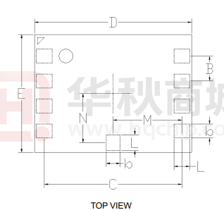
2.2 Package Dimensions
TOP VIEW
SIDE VIEW
2
�CSNP32GCR01-BOW
Common Dimensions
Symbol
b
L
B
C
D
E
H
M
N
Min
0.65
0.75
6.90
7.90
6.10
0.70
-
Nom
0.70
0.80
1.27(Typ)
7.00
8.00
6.20
0.80
3.5(Typ)
2.6(Typ)
Max
0.75
0.85
7.10
8.10
6.30
0.90
-
SDNAND Package Dimensions (unit: mm)
3
Note
�CSNP32GCR01-BOW
3. Performance
Parameter
Temperature
Range
Work Model
-0°~ 70℃
Storage Model
- 25°~ 85℃
Work Model
8% to 95%, Non-condensing
Storage Model
8% to 95%, Non-condensing
Humidity
4
�CSNP32GCR01-BOW
4. DC Characteristics
Symbol
PARAMETER
VIL
Input low voltage
VIH
Input high voltage
VOL
Output low voltage
VOH
Output high voltage
IIN
Input leakage current
IOUT
CONDITIONS
MIN
IOP
Operation current
UNITS
VSS-0.3
0.25VCC
V
0.625VCC
VCC+0.3
V
0.125VCC
V
@VCC_min
IOH=100μA
0.75VCC
@VCC_min
VIN=VCC or 0
current
Standby current
MAX
IOL=100μA
Tri-state output leakage
ISTBY
TYP
3.3V@clock
stop
3.3v@50MHz
(Write)
3.3v@50MHz
(Read)
5
V
-10
+/-1
10
μA
-10
+/-1
10
μA
150
200
μA
15
25
mA
15
25
mA
�CSNP32GCR01-BOW
5. AC Characteristics
5.1 Bus Timing (Default Mode)
SYMBOL
PARAMETER
MIN
MAX
UNIT
FSD
SD clock frequency
0
25
MHz
TWL
Clock low time
10
ns
TWH
Clock high time
10
ns
TTLH
Clock rise time
10
ns
TTHL
Clock fall time
10
ns
TISU
Input setup time
5
ns
TIH
Input hold time
5
ns
TODLY
Output delay time
0
14
5.2 Bus Timing (High-speed Mode)
6
ns
NOTE
�CSNP32GCR01-BOW
SYMBOL
PARAMETER
MIN
MAX
UNIT
FSD
SD clock frequency
0
50
MHz
TWL
Clock low time
10
ns
TWH
Clock high time
10
ns
TTLH
Clock rise time
10
ns
TTHL
Clock fall time
10
ns
TISU
Input setup time
5
ns
TIH
Input hold time
5
ns
TODLY
Output delay time
0
TOH
Output hold time
2.5
14
ns
ns
7
NOTE
�CSNP32GCR01-BOW
6. Reference Design
Note:
RDAT and RCMD (10K~100 kΩ) are pull-up resistors protecting the CMD and the DAT lines against bus floating when SDNAND is in a
high-impedance mode.
The host shall pull-up all DAT0-3 lines by RDAT, even if the host uses the SDNAND as 1-bit mode only in SD mode. It is
recommended to have 2.2uF capacitance on VCC.
RCLK reference 0~120 Ω.
8
�
很抱歉,暂时无法提供与“CSNP32GCR01-BOW”相匹配的价格&库存,您可以联系我们找货
免费人工找货- 国内价格
- 1+38.64000
- 10+36.34000
- 30+35.88000
- 100+34.50000
- 国内价格
- 1+82.40400
- 10+78.22440
- 30+70.96680
- 100+64.63800
