Application Note: SY8823
Ultra Low Quiescent Current, 2.0MHz, 3.5A
Synchronous Step Down Regulator
•
•
•
Ordering Information
Tempera ture Code
Packa ge Code
Optiona l Spec Code
•
•
•
•
fid
Set Top Box
Net PC
Mini-Notebook PC
Access Point Router
on
Co
rp
.C
Typical Applications
io
nc
l-P
Note
3.5A
tia
Package Type
QFN2x1.5-8
Applications
en
Ordering Number
SY8823QUC
fo
rZ
re
SY8823 □(□□)□
Input voltage range: 2.5V to 5.5V
2.0 MHz switching frequency
3.5A maximum output current
Peak current mode control for the fast transient speed
100% drop out function
Typical 18uA quiescent current
Low RDS(ON) for internal switches (PFET/NFET):
55mΩ/35mΩ
Hic-cup mode protection for hard short condition
RoHS Compliant and Halogen Free
Compact package: QFN2x1.5-8
d
SY8823 operates over a wide input voltage range from
2.5V to 5.5V and integrates main switch and synchronous
switch with very low RDS (ON) to minimize the conduction
loss.
•
•
•
•
•
•
•
re
SY8823 is a high efficiency ultra low quiescent current,
2.0MHz synchronous step-down DC-DC regulator IC
capable of delivering up to 3.5A output current.
om
Features
pa
General Description
Efficiency vs. Load Current
100
95
90
rg
y
85
80
VIN=3.3V,VOUT=1.8V
VIN=4.2V,VOUT=1.8V
VIN=5.0V,VOUT=1.8V
le
75
Si
70
1
10
100
1000
10000
Load Current (mA)
Figure 1. Schematic Diagram
AN_SY8823 Rev.0.9C
Figure 2. Efficiency Figure
Silergy Corp. Confidential-Prepared for Customer Use Only
1
�SY8823
Pin Number
PVIN
1
PGND
LX
2
3
PG
4
FB
5
SGND
6
SVIN
7
EN
8
Pin Description
Supply voltage for power circuit. Decouple this pin to ground with at least 22uF
ceramic cap.
Power ground pin.
Inductor pin. Connect this pin to the switching node of inductor
Power good indicator (Open drain output). Low if the output < 90% of regulation
voltage; High otherwise. Connect a pull-up resistor to the input.
Output feedback pin. Connect this pin to the center point of the output resistor
divider (as shown in Figure 1) to program the output voltage:
VOUT=0.6V*(1+RH/RL).
Signal ground pin.
Supply voltage for control circuit. Decouple this pin to ground with at least 1uF
ceramic cap.
Enable input pin. Integrated 4MΩ pull down resistor.
id
en
tia
l-P
re
pa
re
d
Pin Name
fo
rZ
Part Number
Package type
Top Mark①
SY8823QUC
QFN2x1.5-8
VPxyz
Note① : x=year code, y=week code, z= lot number code.
io
nc
om
Pinout (top view)
Absolute Maximum Ratings
rg
y
Co
rp
.C
on
f
(Note 1)
All pins --------------------------------------------------------------------------------------------------------------------------- 6V
Power Dissipation, PD @ TA = 25°C QFN2x1.5-8---------------------------------------------------------------------------1W
Package Thermal Resistance (Note 2)
θ JA ------------------------------------------------------------------------------------------------------------- 100°C/W
θ JC --------------------------------------------------------------------------------------------------------------- 15°C/W
Junction Temperature Range ---------------------------------------------------------------------------------------------- 150°C
Lead Temperature (Soldering, 10 sec.) ---------------------------------------------------------------------------------- 260°C
Storage Temperature Range ------------------------------------------------------------------------------------ -65°C to 150°C
Dynamic LX voltage in 10ns duration --------------------------------------------------------------------- -4V to +7V
le
Recommended Operating Conditions (Note 3)
Si
Supply Input Voltage ----------------------------------------------------------------------------------------------- 2.5V to 5.5V
Junction Temperature Range ----------------------------------------------------------------------------------- -40°C to 125°C
Ambient Temperature Range ------------------------------------------------------------------------------------ -40°C to 85°C
AN_SY8823 Rev. 0.9C
Silergy Corp. Confidential- Prepared for Customer Use Only
2
�SY8823
Electrical Characteristics
(VIN = 5V, VOUT = 2.5V, L = 0.47uH, COUT = 22uF, TA = 25°C, unless otherwise specified)
Test Conditions
Peak Current Limit
ILIM
4.5
EN rising threshold
EN falling threshold
Input UVLO threshold
UVLO hysteresis
Oscillator Frequency
PGOOD Under-voltage Threshold
Short Circuit Protection Threshold
Min ON Time
Soft Start time
Output Discharge Switch On
Resistance
Thermal Shutdown Temperature
Thermal Shutdown Hysteresis
VENH
VENL
VUVLO
VHYS
FOSC
VFB,LV
VSCP
1.5
IOUT=0, VFB=VREF ⋅ 105%
EN=0
18
0.1
0.6
55
35
Max
5.5
1
0.609
80
55
7.5
d
pa
re
IOUT=500mA
re
l-P
Unit
V
µA
µA
V
mΩ
mΩ
A
0.15
2
0.55
0.26
80
1
V
V
V
V
MHz
V
V
ns
ms
50
Ω
150
15
°C
°C
0.4
2.5
id
en
tia
TSD
THYS
Typ
fo
rZ
0.591
30
15
TSS
RDSC
Min
2.5
om
Symbol
VIN
IQ
ISHDN
VREF
RDS(ON),P
RDS(ON),N
io
nc
Parameter
Input Voltage Range
Quiescent Current
Shutdown Current
Feedback Reference Voltage
PFET RON
NFET RON
on
f
Note 1: Stresses beyond the “Absolute Maximum Ratings” may cause permanent damage to the device. These are
stress ratings only. Functional operation of the device at these or any other conditions beyond those indicated in the
operational sections of the specification is not implied. Exposure to absolute maximum rating conditions for
extended periods may affect device reliability.
.C
Note 2: θ JA is measured in the natural convection at TA = 25°C on a low effective single layer thermal conductivity
test board of JEDEC 51-3 thermal measurement standard.
Si
le
rg
y
Co
rp
Note 3: The device is not guaranteed to function outside its operating conditions.
AN_SY8823 Rev. 0.9C
Silergy Corp. Confidential- Prepared for Customer Use Only
3
�SY8823
+
l-P
re
pa
re
d
fo
rZ
io
nc
om
Block Diagram
Si
le
rg
y
Co
rp
.C
on
f
id
en
tia
-
AN_SY8823 Rev. 0.9C
Silergy Corp. Confidential- Prepared for Customer Use Only
4
�SY8823
Si
le
rg
y
Co
rp
.C
on
f
id
en
tia
l-P
re
pa
re
d
fo
rZ
io
nc
om
Typical Performance Characteristics
AN_SY8823 Rev. 0.9C
Silergy Corp. Confidential- Prepared for Customer Use Only
5
�SY8823
Output Ripple
(VIN=5.0V, VOUT=1.8V, IO=3.5A)
20mV/div
VLX
2V/div
IL
2A/div
fo
rZ
io
nc
om
∆VOUT
d
Time (400ns/div)
Shutdown from Enable
(VIN=5.0V, VOUT=1.8V, IO=3.5A)
VLX
5V/div
IL
2A/div
pa
re
2V/div
l-P
VOUT
id
en
tia
5V/div
on
f
EN
re
Startup from Enable
(VIN=5.0V, VOUT=1.8V, IO=3.5A)
5V/div
VOUT
2V/div
VLX
5V/div
IL
2A/div
Time (200µs/div)
Si
le
rg
y
Co
rp
.C
Time (800µs/div)
EN
AN_SY8823 Rev. 0.9C
Silergy Corp. Confidential- Prepared for Customer Use Only
6
�Si
le
rg
y
Co
rp
.C
on
f
id
en
tia
l-P
re
pa
re
d
fo
rZ
io
nc
om
SY8823
AN_SY8823 Rev. 0.9C
Silergy Corp. Confidential- Prepared for Customer Use Only
7
�SY8823
Applications Information
.C
on
f
Because of the high integration in SY8823, the
application circuit based on this regulator IC is rather
simple. Only input capacitor CIN, output capacitor COUT,
inductor L and feedback resistors (R1 and R2) need to
be selected for the targeted applications.
rg
y
Co
rp
Feedback resistor divider R1 and R2
Choose R1 and R2 to program the proper output voltage.
To minimize the power consumption under light load,
it is desirable to choose large resistance values for both
R1 and R2. A value between 10k and 1M is
recommended for both resistors. If R1=100k is chosen,
then R2 can be calculated to be:
0.6 R1
(Ω)
VOUT - 0.6
Si
le
R2 =
VOUT
R1
FB
GND
R2
AN_SY8823 Rev. 0.9C
om
D (1 -D ) (A)
io
nc
This formula has a maximum at VIN=2×VOUT condition,
where ICIN_RMS=IOUT/2.
re
d
fo
rZ
With the maximum load current at 3.5A, a typical X5R
or better grade ceramic capacitor with 6.3V rating and
greater than 22uF capacitance can handle this ripple
current well. To minimize the potential noise problem,
place this ceramic capacitor really close to the PVIN
and GND pins. Care should be taken to minimize the
loop area formed by CIN, PVIN and GND pins.
pa
A 1µF ceramic capacitor needs to be added across
SVIN and GND.
Output capacitor COUT
Both steady state ripple and transient requirements
must be taken into account when selecting this
capacitor. For the best performance, it is recommended
to use X5R or better grade ceramic capacitor with 6.3V
rating and more than two pcs 22µF capacitors.
id
en
tia
SY8823 senses the output voltage conditions for the
fault protection. If the DC output voltage is about 3%
over the regulation level, both switches turn off and
remain in the off state. If the DC output voltage is
below 42% of the regulation level, the IC will enter
hic-up short protection mode. When the output voltage
is below 42% of the regulation, the frequency is folded
back to 25% of the normal frequency and the current
limit is decreased to 55% of the normal current limit to
prevent the inductor current runaway and to reduce the
power dissipation within the IC under true short circuit
conditions.
I C IN _R M S = I O U T ×
re
SY8823 is an ultra low quiescent current synchronous
buck regulator IC that integrates the PWM control, top
and bottom switches on the same die to minimize the
switching losses and conduction losses. With low
RDS(ON) power switches and proprietary PWM control,
this regulator IC achieves a higher efficiency with high
switching frequency to minimize the external inductor
and capacitor size, and thus achieving the minimum
solution footprint.
Input capacitor CIN
This ripple current through input capacitor is calculated
as:
l-P
Operation
Output inductor L:
There are several considerations in choosing this
inductor.
1) Choose the inductance to provide the desired
ripple current. It is suggested to choose the ripple
current to be about 40% of the maximum average
input current. The inductance is calculated as:
L=
VOUT (1 − VOUT /VIN_MAX )
FSW × IOUT_MAX × 40%
(H)
Where FSW is the switching frequency and
the maximum load current.
IOUT_MAX is
SY8823 is less sensitive to the ripple current variations.
Consequently, the final choice of inductance can be
slightly off the calculation value without significantly
impacting the performance.
2) The saturation current rating of an inductor must
be selected to guarantee an adequate margin to the
peak inductor current under full load conditions.
Silergy Corp. Confidential- Prepared for Customer Use Only
8
�SY8823
om
io
nc
fo
rZ
4) The components RL, RH and the trace connecting to
the FB pin must NOT be adjacent to the LX node on
the PCB layout to minimize the noise coupling to FB
pin.
Si
le
rg
y
Co
rp
.C
on
f
id
en
tia
Load Transient Considerations:
SY8823 integrates the compensation components to
achieve good stability and fast transient responses.
Adding a 10pF~22pF ceramic capacitor in parallel with
R1 may further speed up the load transient responses.
3) The PCB copper area associated with LX pin must
be minimized to improve the noise immunity.
d
Power Good Indication
PG is an open-drain output pin. Connect an above 100k
pull-up resistor to VIN. PG pin will output high after the
output voltage exceeds 90% of normal output voltage.
2) The decoupling capacitor of PVIN and SVIN must
be placed as close as possible to the pins. The loop area
formed by the capacitors and GND must be minimized.
re
Enable Operation
Pulling the EN pin low (1.5V) will turn on the IC again.
1) It is desirable to maximize the PCB copper area
connecting to GND pin to achieve the best thermal and
noise performance. Reasonable vias are suggested to be
placed underneath the ground pad to enhance the
soldering quality and thermal performance
pa
3) The DCR of the inductor and the core loss at the
switching frequency must be low enough to
achieve the desired efficiency requirement. It is
desirable to choose an inductor with DCR IOUT, MAX +
AN_SY8823 Rev. 0.9C
Silergy Corp. Confidential- Prepared for Customer Use Only
9
�SY8823
re
pa
re
d
fo
rZ
io
nc
om
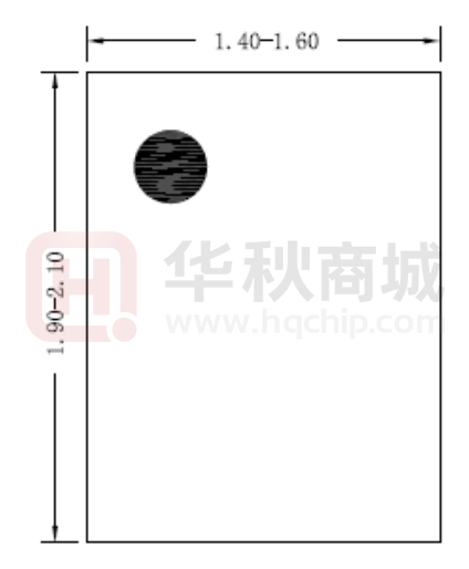
QFN2x1.5-8 Package Outline Drawing
Bottom View
Si
le
rg
y
Co
rp
.C
on
f
id
en
tia
l-P
Top View
Side View
Notes:
Recommended PCB layout
(Reference only)
All dimension in millimeter and exclude mold flash & metal burr
AN_SY8823Rev. 0.9C
Silergy Corp. Confidential- Prepared for Customer Use Only
10
�SY8823
Taping & Reel Specification
re
pa
re
d
fo
rZ
io
nc
om
1. QFN2x1.5 taping orientation
l-P
Feeding direction
.C
on
f
id
en
tia
2. Carrier Tape & Reel specification for packages
Si
le
rg
y
Co
rp
Reel
Size
Package types
Tape
width
(mm)
Pocket
pitch(mm)
Reel size
(Inch)
Trailer
length(mm)
Leader length
(mm)
Qty per
reel
QFN2x1.5
8
4
7
400
160
3000
3. Others: NA
AN_SY8823Rev. 0.9C
Silergy Corp. Confidential- Prepared for Customer Use Only
11
�
很抱歉,暂时无法提供与“SY8823QUC”相匹配的价格&库存,您可以联系我们找货
免费人工找货