Specifications for Wire Wound Chip Common Mode Choke Coil
1. Features
● High common mode impedance at high frequency effects excellent noise suppression performance.
● FDCW2012series realizes small size and low profile 2.0*1.2*1.2 mm.
● 100% Lead(Pb)& Halogen-Free and RoHS compliant.
2. Applications
● Power switch and servers.
● USB communication.
● Telecommunication applications.
● Panel link for LCD panels.
●Countering common mode noise affecting signals in high-speed lines.
3. Product Identification
FDCW
①
2012
②
-2
③
-900
④
T
⑤
F
⑥
① FDCW ---------- Series name
② 2012 ---------- Dimension
③
2
---------- 2 lines
④ 900
---------- Common Mode Impedance(Ω)
⑤
T
----------
Packing(Tape & Reel)
⑥
F
---------- HSF Products(Hazardous Substance Free Products)
4. Dimensions
Recommend Land Patter
Unit:mm
A
B
C
D
E
2.00±0.20
1.20±0.20
1.20±0.20
0.5TYP
0.5TYP
第 1 页 共 9 页
�Specifications for Wire Wound Chip Common Mode Choke Coil
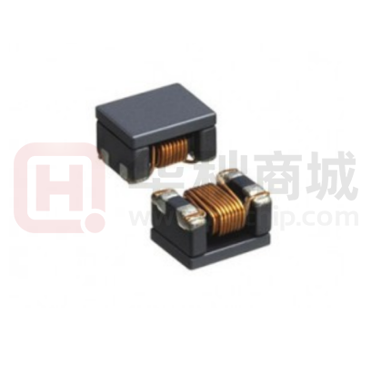
5. Structure and Components
①
②
No
Part Name
Material Name
①
②
③
④
Lid
Ni-Zn Ferrite
Epoxy
Epoxy resin
Wire
Enameled copper wire
Core
Ni-Zn Ferrite
④
Electrode
structure
Ag+Ni+Sn plating
⑤
⑤
6. Schematic Diagram
7. MEASURING CIRCUITS 2LINE
1)Common mode:
2)Differential mode:
第 2 页 共 9 页
③
�Specifications for Wire Wound Chip Common Mode Choke Coil
8.Electrical Characteristics
Z (共模阻抗)
@100MHZ
Part No.
Ω
±25%
Rated Voltage
Rated Current
DCR
IR
mΩ
MΩ
V
mA
MAX
MIN
/
MAX
(Vdc)
FDCW2012-2-300TF
30
200
10
50
450
FDCW2012-2-500TF
50
250
10
50
550
FDCW2012-2-750TF
75
250
10
50
400
FDCW2012-2-900TF
90
300
10
50
400
FDCW2012-2-121TF
120
300
10
50
400
FDCW2012-2-161TF
160
350
10
50
350
FDCW2012-2-181TF
180
350
10
50
350
FDCW2012-2-201TF
200
350
10
50
300
FDCW2012-2-221TF
220
350
10
50
300
FDCW2012-2-251TF
250
400
10
50
300
FDCW2012-2-261TF
260
400
10
50
300
FDCW2012-2-301TF
300
400
10
50
290
FDCW2012-2-361TF
360
400
10
50
300
FDCW2012-2-371TF
370
450
10
50
280
FDCW2012-2-481TF
480
550
10
50
200
FDCW2012-2-501TF
500
550
10
50
200
FDCW2012-2-601TF
600
550
10
50
300
FDCW2012-2-671TF
670
600
10
50
180
FDCW2012-2-681TF
680
700
10
50
180
FDCW2012-2-751TF
750
800
10
50
150
FDCW2012-2-801TF
800
1000
10
50
300
FDCW2012-2-901TF
900
1000
10
50
100
FDCW2012-2-102TF
1000
1000
10
50
100
Notes
1. All test data is referenced to 25 °C ambient.
2. Operating temperature range - 40 °C to + 85 °C.
3. Irms (A):DC current (A) that will cause an approximate ΔT of 40 °C(reference ambient temperature is 25 °C).
4. The part temperature (ambient + temp rise) should not exceed 125 °C under worst case operating conditions.
Circuit design, component placement, PWB trace size and thickness, airflow and other cooling provisions.
all affect the part temperature. Part temperature should be verified in the end application.
第 3 页 共 9 页
�Specifications for Wire Wound Chip Common Mode Choke Coil
9.Typical impedance vs. frequency
FDC W2012
Common mode
Differential mode
FDC W2012
Common mode
Common mode
Differential mode
第 4 页 共 9 页
�Specifications for Wire Wound Chip Common Mode Choke Coil
10.Reliability Test
Items
Operating life
Requirements
Test Methods and Remarks
1. No visible mechanical damage
1. Reflow 2 times
2. Impedance change: Within±
2. temperature: 155± 2 ℃
20%
3. Insulation resistance:10MΩ min
Resistance to
1. No visible mechanical damage
1.
Soldering Heat
2. Impedance change: Within±20%
secs ,Cycles :2 times..Re-flowing Profile: Please refer to Fig-1
Solder on PCB to Reflow test Peak Temp. 260±5℃ 5~10
2.
Test board thickness: 1.5mm
3.
Test board material: glass epoxy resin
4.
The specimen shall be stored at standard atmospheric conditions
for 1 hour, after which the measurement shall be made.product showed
no damage under microscope.
Fig-1
High
Temperature
1. No visible mechanical damage
1. Temperature: 125±2℃
2. Impedance change: Within±
2. Duration: 1000 hours
20%
The specimen shall be stored at standard atmospheric
3. Insulation resistance:10MΩ min
conditions for 1 hour, after which the measurement shall
be made.
Steady
damp-heat
1. No visible mechanical damage
1. Temperature:85℃
2. Impedance change: Within±
2. Humidity: 85% RH
20%
3. Duration:1000 hours
3. Insulation resistance:10MΩ min
4. The specimen shall be stored at standard
atmospheric conditions for 1 hour, after which the
measurement shall be made.
Mechanical
Vibration
1. No visible mechanical damage
1. Frequency: 10HZ~55HZ~10HZ/Min Cycles
2. Impedance change: Within±
2. Amplitude: 1.5 mm
20%
3. Directions: X,Y,Z
4. Time: 2 hours in each directions (total of 6 hours)
第 5 页 共 9 页
�Specifications for Wire Wound Chip Common Mode Choke Coil
Items
Thermal Shock
Requirements
Test Methods and Remarks
1. No visible mechanical damage
1. Temperature and time: -40℃ for 30±3 min→125℃ for
2. Impedance change: Within±
30±3min, please refer to Fig-2
20%
2. Transforming interval: Max. 3 Min
3. Insulation resistance:10MΩ min
3. Tested cycle: 1000 cycles
4. The specimen shall be stored at standard atmospheric
conditions for 1 hour, after which the measurement shall
be made.
Fig-2
Salt Spray
1. No visible mechanical damage
1. Salt concentration: (5 ± 1)% (mass percent)
2. Impedance change: Within±
2. pH value:6.5 - 7.2
20%
3. temperature: 35 ± 2 ℃
4. humidity: 85%
5. time: 24 hours
6. in normal temperature and humidity for 1 ~ 2 hours,
testing inductance, the inductance value change can not
be more than before test ± 10%.
Terminal
strength
No visible mechanical damage
1. The electrode of the inductor is soldered to the PCB,
to Fig-3 Then apply a force in the
direction of the arrow.
2. 5N force.
3. Keep time: 10(±1)s
The first three tests were OK, and the force was applied
until the peak value of the product peeling. The test
speed was set in the range of
Fig-3
第 6 页 共 9 页
3 ~ 8mm/min.
�Specifications for Wire Wound Chip Common Mode Choke Coil
11 . Packaging Information
1) Tape Packaging Dimensions
(Unit:mm)
Type
FDCW
2012
W
P1
A0
B0
K0
t
E
F
P2
D0
D1
P0
8.00
4.00
1.50
2.30
1.45
0.20
1.75
3.50
2.00
1.55
0.80
4.00
±0.10
±0.10
±0.10
±0.10
±0.10
±0.05
±0.10
±0.10
±0.10
±0.05
±0.05
±0.10
2)Leader and blank portion
3)Taping Drawings
第 7 页 共 9 页
�Specifications for Wire Wound Chip Common Mode Choke Coil
4)Reel Dimensions(Unit:mm)
5)Packaging Quantity
Type
FDCW2012
Standard Quantity
Reel
Inner box
2000 pcs / reel
5Reel / box (10000 pcs)
6)Peel force of top cover tape
The peel speed shall be about 300mm/minute.
The peel force of top cover tape shall be between 10 to 100gf.
第 8 页 共 9 页
Carton box
10 Middle boxes,
(100000 pcs)
�Specifications for Wire Wound Chip Common Mode Choke Coil
7)Reel Label
●
Label on the reel
• Customer's part Number
• Lot Number
• Quantity
• date code
●
Shipping Label
• Customer's part Number
• Manufacturer's part Number
• Quantity
• date code
8)Inner Box
Packaging Type
A (mm)
B (mm)
C (mm)
Inner box
188
195
67
Packaging Type
L (mm)
W (mm)
H (mm)
Carton
390
350
215
9)Carton
Label
第 9 页 共 9 页
�
很抱歉,暂时无法提供与“FDCW2012-2-201TF”相匹配的价格&库存,您可以联系我们找货
免费人工找货