UMW
R
1N4001(A1)-1N4007(A7)
Surface Mount General Purpose Silicon Rectifiers
Reverse Voltage - 50 to 1000 V
Forward Current - 1 A
PINNING
PIN
DESCRIPTION
1
Cathode
2
Anode
A7
1
2
Top View
Marking Code: A1-A7
Simplified outline SOD-123FL and symbol
Maximum Ratings and Electrical characteristics
Ratings at 25 °C ambient temperature unless otherwise specified.
Single phase half-wave 60 Hz, resistive or inductive load, for capacitive load current derate by 20 %.
Symbols
Parameter
1N4001 1N4002
1N4003
1N4004
1N4005
1N4006
1N4007
Units
Maximum Repetitive Peak Reverse Voltage
V RRM
50
100
200
400
600
800
1000
V
Maximum RMS voltage
V RMS
35
70
140
280
420
560
700
V
Maximum DC Blocking Voltage
V DC
50
100
200
400
600
800
1000
V
Maximum Average Forward Rectified Current
at Ta = 65 °C
I F(AV)
1
A
Peak Forward Surge Current 8.3 ms Single Half
I FSM
Sine Wave Superimposed on Rated Load
JEDEC
Method
(
)
25
A
Maximum Instantaneous Forward Volta
g e at
1A
VF
1.1
V
IR
5
100
μA
Cj
4
pF
RθJA
180
°C/W
T j , T stg
-55 ~ +150
°C
Maximum DC Reverse Current
at Rated DC Blocking Voltage
Typical Junction Capacitance
Typical Thermal Resistance
Ta = 25 °C
Ta =125 °C
1)
2)
Operating and Storage Temperature Range
1)Measured at 1 MHz and applied reverse voltage of 4 V D.C
2)Thermal resistance from junction to ambient at 0.375" (9.5 mm) lead length, P.C.B. mounted
www.umw-ic.com
1
友台半导体有限公司
�UMW
R
1N4001(A1)-1N4007(A7)
Fig.2 Typical Instaneous Reverse
Characteristics
Fig.1 Forward Current Derating Curve
Instaneous Reverse Current ( μ A)
Average Forward Current (A)
1.2
1.0
0.8
0.6
0.4
0.2
Single phase half-wave 60 Hz
resistive or inductive load
0.0
25
50
75
100
125
150
175
100
T J =150°C
T J =125°C
10
T J =100°C
1.0
T J =75°C
T J =50°C
0.1
T J =25°C
0.01
Fig.3 Typical Forward Characteristic
800
Fig.4 Typical Junction Capacitance
12
Junction Capacitance ( pF)
1.0
2 5°
C
TJ =
°C
00
TJ
=1
=1
50
°C
0.5
TJ
Instaneous Forward Current (A)
600
Instaneous Reverse Voltage (V)
Ambient Temperature (°C)
0.2
0.1
0.6
400
200
0
0.7
0.8
0.9
1.0
8
6
4
2
0
0
1.1
Instaneous Forward Voltage (V)
www.umw-ic.com
10
5
10
15
20
25
30
35
40
Reverse Voltage (V)
2
友台半导体有限公司
�UMW
R
1N4001(A1)-1N4007(A7)
PACKAGE OUTLINE
Plastic surface mounted package; 2 leads
C
A
∠ALL ROUND
HE
VM
D
A
E
A
UNIT
mm
mil
A
C
D
E
HE
max
1.25
0.16
2.9
1.9
3.9
min
0.95
0.14
2.6
1.6
3.5
max
49.2
6.3
114
74.8
154
min
37.4
5.5
102
63.0
138
5°
7.9
Marking
Type number
1.4
(55)
1.9
(75)
1.9
(75)
Unit: mm
(mil)
www.umw-ic.com
∠
0.2
The recommended mounting pad size
1.4
(55)
V
3
Marking code
1N4001
A1
1N4002
A2
1N4003
A3
1N4004
A4
1N4005
A5
1N4006
A6
1N4007
A7
友台半导体有限公司
�UMW
R
1N4001(A1)-1N4007(A7)
• Recommended condition of flow soldering
Preliminary Heating
300
Soldering
Cooling (in air)
Temperature of Soldering (°C)
265°C
250
245°C
200
150
120°C
100
100°C
50
0
2 to 5 min
more than 1 min
less than 10s
• Recommended condition of reflow soldering
Temperature of Soldering (°C)
300
Peak Temperature
245 to 260°C, 10s max.
250
Reflow Heating Rate
1 to 5°C / s
200
150
100
50
Pre Heating Rate
1 to 5°C / s
Preliminary Heating
130 to 170°C,
50 to 120s
Soldering
230°C
20 to 30s
Cooling
more than 60s
0
2 times max.
Recommended peak temperature is over 245 °C. If peak temperature is below 245 °C, you may adjust
the following parameters; time length of peak temperature (longer), time length of soldering (longer),
thickness of solder paste (thicker)
• Condition of hand soldering
Temperature: 370°C
Time: 3s max.
Times: one time
• Remark:
Lead free solder paste (96.5Sn/3.0Ag/0.5Cu)
www.umw-ic.com
4
友台半导体有限公司
�
很抱歉,暂时无法提供与“1N4007(A7)”相匹配的价格&库存,您可以联系我们找货
免费人工找货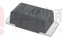


 工商网监
湘ICP备2023018690号
工商网监
湘ICP备2023018690号