LSM0805 Series
0805 SMD LED Package
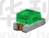
2.0 x1.25x 1.1 mm SMD Chip LED
LSM0805452V Green SMD LED. Low Profile Surface Mount LED with
High intensity light output and low power consumption
Application
• Wearable and Portable Devices
• Automotive Features
• Navigations Systems
• Home and Smart Appliance
• Backlit Keypads
• Medical Devices
• Health Care Application
• Industrial Control Systems
• Status Indicator
Key Features
• 2.0 x 1.25 mm (0805 package/2012 metric) Chip SMD LED
• 1.1 mm [0.043 in] in thickness
• Low power consumption
• Rectangle flat top LED
• Wide viewing angle (120°)
• Optimized light coupling by inter reflector
• GaInP technology
• Top emitting package
• Small 0805 LED package, flexible application with small space required.
• Available in a range of colors: red, white, green, blue and yellow making it ideal for status indication
• Cost-efficient solution for low-power and compact electronic equipment designs
• Compatible with automatic placement equipment and available in automation-friendly tape and reel
• Ideal for special configurations for automated PC board assembly and space-sensitive applications
• Pb-free
• Moisture sensitivity level: 3
• Package 3,000 pieces per reel
• Compliant with RoHS and REACH
vcclite.com | 1.800.522.5546
LSM0805452V | 05/19 | Page 1 of 8
�Ordering Data
Product Dimensions
1.25
[.049]
R0.20
[.008]
1.40
[.055]
Polarity
2.0
[.079]
1.20
[.047]
1.1
[.043]
0.50
[.02]
Recommended Soldering Pattern
1.1
[.043]
1.0
[.039]
1.35
[.053]
0.40
[.016]
0.40
[.016]
2.0
[.079]
Notes:
1. All dimensions are in mm [in]
2. Tolerance is ±0.1 mm [.004 in] unless otherwise noted
3. The specifications, characteristics and technical data described in the datasheet are subject to change without prior notice.
vcclite.com | 1.800.522.5546
LSM0805452V | 05/19 | Page 2 of 8
�Product Specifications
Absolute Maximum Ratings (ta=25˚C)
Notes:
1. Tolerance of Luminous Intensity ±3%
2. Tolerance of Dominant Wavelength ±1nm
3. Tolerance of Forward Voltage ±0.03V
vcclite.com | 1.800.522.5546
LSM0805452V | 05/19 | Page 3 of 8
�Product Specifications
Typical Electrical-Optical Characteristics Curves
vcclite.com | 1.800.522.5546
LSM0805452V | 05/19 | Page 4 of 8
�Reliability Data
The reliability of products shall be satisfied with items listed below. Confidence level: 90%
LTPD: 10%
vcclite.com | 1.800.522.5546
LSM0805452V | 05/19 | Page 5 of 8
�Recommended Reflow Soldering Profile
Reflow Soldering
Use the conditions shown in the figure below for PB-Free Reflow Soldering.
• Reflow soldering should not be done more than two times.
• Stress on the LEDs should be avoided during heating in soldering process.
• After soldering, do not handle the product before its temperature drops down to room temperature.
vcclite.com | 1.800.522.5546
LSM0805452V | 05/19 | Page 6 of 8
�Precautions
• Storage
Moisture proof and anti-electrostatic package with moisture absorbent material are used, to keep moisture to
a minimum.
Before opening the package, the product should be kept at 30°C or less and humidity less than 60%Rh, and be used
within a year.
After opening the package, the product should be stored at 30°C or less and humidity less than 10%RH, and be
soldered within 24 hours. It is recommended that the product be operated at the workshop condition of 30°C or less
and humidity less than 60%RH.
If the moisture absorbent material has faded away or the LEDs have exceeded the storage time. Baking should be
performed based on the following condition: (60+5C) for 12 hours
• Static Electricity
Static electricity or surge voltage damages the LEDs. Damaged LEDs will show some unusual characteristics such as
the forward voltage becomes lower, or the LEDs do not light at the low current, even not light.
All devices, equipment, and machinery must be properly grounded. At the same time, it is recommended that
wristbands or anti-electrostatic gloves, anti-electrostatic containers be used when dealing with the LEDs.
Circuit Design Notes
• Design Consideration
In designing a circuit, the current through each LED must not exceed the absolute maximum rating specified for each
LED. In the meanwhile, resistors for protection should be applied, otherwise slight voltage shift will cause big current
change, burn out may happen.
It is recommended to use Circuit A which regulates the current flowing through each LED rather than Circuit B in
forward Voltage (Vf) of the LEDs. In the worst case, some LED may be subjected to stresses in excess of the Absolute
Maximum Rating
• Thermal Design
Is paramount importance because heat generation may result in the Characteristics decline, such as brightness
decreased, Color changed and so on. Please consider the heat generation of the LEDs when making the
system design.
vcclite.com | 1.800.522.5546
LSM0805452V | 05/19 | Page 7 of 8
�Tape and Reel Specifications
Notes:
1. All dimensions are in mm [in]
2. Tolerance is ±0.1 mm [.004 in] unless otherwise noted
3. The specifications, characteristics and technical data described in the datasheet are subject to change without prior notice.
Compliances and Approvals
vcclite.com | 1.800.522.5546
LSM0805452V | 05/19 | Page 8 of 8
�
很抱歉,暂时无法提供与“LSM0805452V”相匹配的价格&库存,您可以联系我们找货
免费人工找货- 国内价格 香港价格
- 1+2.478171+0.32054
- 10+1.6781110+0.21706
- 100+1.17927100+0.15254
- 500+0.95100500+0.12301
- 1000+0.875301000+0.11322
- 国内价格 香港价格
- 3000+0.777573000+0.10058
- 6000+0.727636000+0.09412
- 9000+0.701999000+0.09080
- 15000+0.6730015000+0.08705
- 21000+0.6557521000+0.08482
- 30000+0.6389030000+0.08264