RS809
Supply Voltage Supervisor with Reset Circuits
1 FEATURES
3 DESCRIPTIONS
•
•
Operating Voltage Range: 1.0V to 5.5V
Low Power Consumption: 40µA (Max)
•
Precision Supply-Voltage Monitor:
2.63V, 2.93V, 3.08V, 4.00V, 4.65V
•
Guaranteed 𝐑𝐄𝐒𝐄𝐓 Valid at VCC= 1.0V
•
200ms Reset Pulse Width
•
•
Voltage Monitor for Power-Fail or LowBattery Warning
Operating Temperature Range:
-40°C to +125°C
̅̅̅̅̅̅̅̅̅ Output
Push-pull, 𝐑𝐄𝐒𝐄𝐓
•
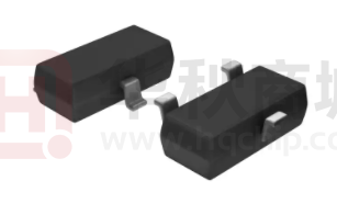
Available in Green Package: SOT23
•
The RS809 microprocessor (µP) supervisory circuits
reduce the complexity and number of components
required to monitor power-supply and battery function
in µP systems. This device significantly improves
system reliability and accuracy compared to separate
ICs or discrete components.
These circuits perform a single function: they assert a
reset signal whenever the VCC supply voltage declines
below a preset threshold, keeping it asserted for at least
200ms after VCC has risen above the reset threshold.
Reset thresholds suitable for operation with a variety of
supply voltages are available.
The RS809 have push-pull outputs. The RS809 have
an active-low RESET output. The reset comparator is
designed to ignore fast transients on VCC, and the
outputs are guaranteed to be in the correct logic state
for VCC down to 1.0V.
2 APPLICATIONS
•
•
Computers
SOC , DSP or Micro controllers
•
Embedded Systems
•
Industrial Equipment
•
Intelligent Instruments
•
•
Critical µP Power Monitoring
Wireless Communications Systems
Low supply current makes the RS809 ideal for use in
portable equipment. The RS809 is available in Green
SOT23 package. It operates over an ambient
temperature range of -40°C to +125°C.
Device Information (1)
(1)
PART NUMBER
PACKAGE
BODY SIZE (NOM)
RS809
SOT23(3)
1.30mm×2.92mm
For all available packages, see the orderable addendum at the
end of the data sheet.
4 TYPICAL APPLICATION
RS3005
IN
OUT
Vcc
Vcc
FPGA,ASIC,DSP
RS809 RESET
GND
REV A.4
RESET
GND
1 / 14
www.run-ic.com
�RS809
Table of Contents
1 FEATURES ...................................................................................................................................................... 1
2 APPLICATIONS ............................................................................................................................................... 1
3 DESCRIPTIONS ............................................................................................................................................... 1
4 TYPICAL APPLICATION ................................................................................................................................. 1
5 Revision History ............................................................................................................................................. 3
6 PACKAGE/ORDERING INFORMATION (1) ..................................................................................................... 4
7 PIN CONFIGURATIONS .................................................................................................................................. 5
8 SPECIFICATIONS ........................................................................................................................................... 6
8.1 Absolute Maximum Ratings (1) ................................................................................................................... 6
8.2 ESD Ratings............................................................................................................................................... 6
8.3 Thermal Information: .................................................................................................................................. 6
8.4 ELECTRICAL CHARACTERISTICS .......................................................................................................... 7
8.5 TYPICAL OPERATING CHARACTERISTICS........................................................................................... 8
9 Function Block Diagram .............................................................................................................................. 10
10 Detailed Description ................................................................................................................................... 10
11 Application and Implementation ............................................................................................................... 11
11.1 Ensuring a Valid RESET Output Down to VCC=0V ................................................................................ 11
11.2 Reset Timing .......................................................................................................................................... 11
12 PACKAGE OUTLINE DIMENSIONS ........................................................................................................... 12
13 TAPE AND REEL INFORMATION .............................................................................................................. 13
2 / 14
www.run-ic.com
�RS809
5 Revision History
Note: Page numbers for previous revisions may different from page numbers in the current version.
Version
Change Date
A.1
2021/08/09
A.2
2022/05/09
A.3
2022/05/10
A.4
2022/11/25
Change Item
Initial version completed
1. Update PACKAGE MARKING on Page 5@RevA.1
2. Update Operating Temperature Range :-40°C to +125°C
Update TYPICAL OPERATING CHARACTERISTICS
1. Update TYPICAL OPERATING CHARACTERISTICS
2. Update PACKAGE/ORDERING INFORMATION
3 / 14
www.run-ic.com
�RS809
6 PACKAGE/ORDERING INFORMATION (1)
PRODUCT
RS809
ORDERING
NUMBER
TEMPERATURE
RANGE
PACKAGE
LEAD
PACKAGE
MARKING (2/3)
PACKAGE OPTION
RS809-1.63YSF3
-40°C ~+125°C
SOT23
809A
Tape and Reel,3000
RS809-2.63YSF3
-40°C ~+125°C
SOT23
809B
Tape and Reel,3000
RS809-2.93YSF3
-40°C ~+125°C
SOT23
809C
Tape and Reel,3000
RS809-3.08YSF3
-40°C ~+125°C
SOT23
809D
Tape and Reel,3000
RS809-4.00YSF3
-40°C ~+125°C
SOT23
809E
Tape and Reel,3000
RS809-4.40YSF3
-40°C ~+125°C
SOT23
809F
Tape and Reel,3000
RS809-4.65YSF3
-40°C ~+125°C
SOT23
809G
Tape and Reel,3000
NOTE:
(1) This information is the most current data available for the designated devices. This data is subject to change without notice and revision
of this document. For browser-based versions of this data sheet, refer to the right-hand navigation.
(2) There may be additional marking, which relates to the lot trace code information (data code and vendor code), the logo or the
environmental category on the device.
(3) A, B, C, D, E, F, G represents different Reset Thresholds.
4 / 14
www.run-ic.com
�RS809
7 PIN CONFIGURATIONS
(TOP VIEW)
GND
1
RS809
RESET
3
VCC
2
SOT23
PIN DESCRIPTION
PIN
NAME
FUNCTION
1
GND
2
̅̅̅̅̅̅̅̅̅
RESET
3
VCC
Ground, reference for all signals.
Active-Low Reset Output remains low while VCC is below the reset threshold, and for at least
200ms after VCC rises above the reset threshold.
Power Supply Voltage that is monitored.
SOT23
5 / 14
www.run-ic.com
�RS809
8 SPECIFICATIONS
8.1 Absolute Maximum Ratings (1)
over operating free-air temperature range (unless otherwise noted) (1)(2)
VCC
VI
(1)
(2)
(3)
(4)
Supply voltage range
Input voltage range
(2)
(2)
MIN
MAX
UNIT
-0.5
6.0
V
-0.5
6.0
V
-0.5
6.0
V
-0.5
VCC+0.5
V
-20
mA
Vo
Voltage range applied to any output in the high-impedance or power-off state
Vo
Voltage range applied to any output in the high or low state (2)(3)
IIK
Input clamp current
VI
很抱歉,暂时无法提供与“RS809-2.93YSF3”相匹配的价格&库存,您可以联系我们找货
免费人工找货- 国内价格
- 10+0.71820
- 100+0.53676
- 300+0.44604
- 3000+0.37800
- 国内价格
- 1+0.42240
- 200+0.27170
- 1500+0.23760
- 3000+0.21010
- 国内价格 香港价格
- 3000+0.464393000+0.05809
- 6000+0.448476000+0.05610
- 9000+0.440499000+0.05510
- 15000+0.4316315000+0.05399
- 21000+0.4264721000+0.05335
- 30000+0.4215030000+0.05272
- 75000+0.4108075000+0.05139
- 150000+0.40435150000+0.05058
- 国内价格 香港价格
- 1+1.229931+0.15384
- 10+0.8238410+0.10305
- 25+0.7188825+0.08992
- 100+0.60850100+0.07611
- 250+0.55521250+0.06945
- 500+0.52327500+0.06545
- 1000+0.496971000+0.06216
