BRIGHT LED ELECTRONICS CORP.
SINCE 1 9 81
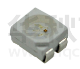
BL-HJDGKKC32M-A
● Features:
1. Emitted Color: Red, Green and Yellow.
●Package Dimensions:
2. Lens Appearance: Water Clear.
3.20
3. 3.5x2.8x1.9mm standard package.
0.80
PIN 1 Mark
1
4
2
3
2.20
2.80
4. Suitable for all SMT assembly methods.
0.70
5. Compatible with infrared and vapor
phase reflow solder process.
6. Compatible with automatic placement
equipment.
3.50
0.15
7. This product doesn’t contain restriction
4
1.90
Substance, comply ROHS standard.
0.90
1.80
1.70
1.80
1
2
3
R
G
K
Polarity
0.70
● Applications:
0.90
0.80
1. Automotive lighting.
0.70
2. Backlighting: LCDs, Key padadvertising.
3. Status indicators: Consumer & industrial
electronics.
4. General use.
NOTES:
1.All dimensions are in millimeters (inches).
2.Tolerance is ±0.10mm (0.004”) unless otherwise specified.
3. Specifications are subject to change without notice.
●
Absolute Maximum Ratings(Ta=25℃)
Parameter
Power Dissipation
Symbol
PD
Color
Rating
Red
75
Green
120
Yellow
75
Unit
mW
Forward Current
IF
30
mA
Peak Forward Current*1
IFP
100
mA
Reverse Voltage
VR
5
V
Operating Temperature
Topr
-40℃~85℃
-
Storage Temperature
Tstg
-40℃~100℃
-
Soldering Temperature
Tsol
See Page 7
-
*1Condition for IFP is pulse of 1/10 duty and 3 msec width.
Ver.1.0 Page: 1 of 9
�BRIGHT LED ELECTRONICS CORP.
SINCE 1 9 81
BL-HJDGKKC32M-A
● Electrical and optical characteristics(Ta=25℃)
Parameter
Symbol
Condition
Forward Voltage
VF
IF=20mA
Luminous Intensity
Iv
IF=20mA
Peak Wavelength
λp
IF=20mA
Dominant Wavelength
λd
IF=20mA
Spectral Line Half-width
Δλ
IF=20mA
Reverse Current
Viewing Angle
IR
2θ1/2
VR=5V
IF=20mA
Color
Min.
Typ.
Max.
Red
Green
Yellow
Red
Green
Yellow
Red
Green
Yellow
Red
Green
Yellow
Red
Green
Yellow
619
520
586
-
2.0
3.2
2.0
220
1800
300
630
525
590
20
30
30
120
2.5
3.6
2.5
630
530
594
10
-
Unit
V
mcd
nm
nm
nm
µA
degree
● Typical Electro-Optical Characteristics Curves
Fig.1 RELATIVE INTENSITY VS. WAVELENGTH
(G)
(Y)
(R)
Fig.2 FORWARD CURRENT
VS. AMBIENT TEMPERATURE
1.0
FORWARD CURRENT (mA)
50
0.5
40
30
20
10
0
20
0
400
500
600
40
80
60
100
AMBIENT TEM PERATURE Ta( ⊥ )
700
W AVELENGTH 竹 (nm)
Fig.4 RELATIVE LUMINOUS INTENSITY
VS. AMBIENT TEMPERATURE
Fig.3 FORWARD CURRENT VS.
FORWARD VOLTAGE
50
3.0
(G)
30
20
10
0
1
2
3
4
(NORMALIZED AT 20mA)
2.5
40
RELATIVE LUMINOUS INTENSITY
FORWARD CURRENT (mA)
(R)
(Y)
2.0
1.5
(Y)
0.5
0
-25
5
0
25
50
75
100
A
AMBIENT
TEM PERATURE Ta( ⊥ )
Fig.6 RADIATION DIAGRAM
Fig.5 RELATIVE LUMINOUS INTENSITY
VS. FORWARD CURRENT
2.0
(R)
(G)
1.0
FORWARD VOLTAGE (V)
0
10
20
(R)
30
(Y)
(G)
RELATIVE RADIANT INTENSITY
RELATIVE LUMINOUS INTENSITY(@20mA)
RELATIVE RADIANT INTENSITY
60
1.5
1.0
0.5
40
1.0
0.9
50
0.8
60
70
0.7
80
90
0
10
20
30
40
50
0.5
0.3
0.1
0.2
0.4
0.6
FORW ARD CURRENT (mA)
Ver.1.0 Page: 2 of 9
�BRIGHT LED ELECTRONICS CORP.
SINCE 1 9 81
BL-HJDGKKC32M-A
● Tapping and packaging specifications(Units: mm)
4
1
2
3
R
G
Y
0.3㊣0.05
●Package Method:(unit:mm)
12 bag/box
2000 pcs/reel
200
Bar Code Label
245
220
220
Aluminum Foil Bag
185
645
6 box/carton
210
470
Ver.1.0 Page: 3 of 9
�BRIGHT LED ELECTRONICS CORP.
SINCE 1 9 81
BL-HJDGKKC32M-A
● Bin Limits (At 20mA)
I n t e n s i t y B i n L i m i ts (At 20 mA) (JD)
COLOR
RED
ITEM
Iv (mcd)
λd (nm)
Spec
140-475
619-630
BIN
MIN
MAX
R
140
210
S
210
317
T
317
475
MIN
MAX
619
630
I n t e n s i t y B i n L i m i ts (At 20 mA) (GK)
COLOR
ITEM
Spec
BIN
Green
Iv (mcd)
715-2400
MIN
MAX
V5
715
W5
X5
X6
525
525
530
520
525
525
530
520
525
525
530
1600
W6
1600
520
1070
V6
1070
λd (nm)
520-530
MIN
MAX
2400
Ver.1.0 Page: 4 of 9
�BRIGHT LED ELECTRONICS CORP.
SINCE 1 9 81
BL-HJDGKKC32M-A
I n t e n s i t y B i n L i m i ts (At 20 mA) (KC)
COLOR
YELLOW
ITEM
Iv (mcd)
λd (nm)
Spec
140-475
586-594
BIN
MIN
MAX
MIN
MAX
586
588
588
590
R5
590
592
R6
592
594
S3
586
588
588
590
S5
590
592
S6
592
594
T3
586
588
588
590
T5
590
592
T6
592
594
R3
R4
140
210
S4
210
317
T4
317
●
BIN: x
x
475
x
YELLOW B I N C O D E
GREEN B I N C O D E
RED B I N C O D E
Notes:
1 . I v : To l e r a n c e f o r e a c h B i n l i m i t i s ± 1 5 %
2 . λ d : To l e r a n c e f o r e a c h B i n l i m i t i s ± 1 n m
3 . B i n c a t e g o r i e s a r e e s ta b l i s h e d f o r c l a s s i f i c a t i o n o f p r o d u c ts .
P r o d u c ts m a y n o t b e a v a i l a b l e i n a l l b i n c a t e g o r i e s .
Ver.1.0 Page: 5 of 9
�BRIGHT LED ELECTRONICS CORP.
SINCE 1 9 81
BL-HJDGKKC32M-A
● Reliability Test
Classification
Test Item
Reference Standard
Operation Life MIL-STD-750:1026
MIL-STD-883:1005
JIS-C-7021
:B-1
High
Temperature MIL-STD-202:103B
High Humidity JIS-C-7021
:B-11
Endurance
Storage
Test
High
MIL-STD-883:1008
Temperature
JIS-C-7021
:B-10
Storage
Low
Temperature JIS-C-7021
:B-12
Storage
Temperature MIL-STD-202:107D
Cycling
MIL-STD-750:1051
MIL-STD-883:1010
JIS-C-7021
:A-4
Thermal Shock MIL-STD-202:107D
Environmental
MIL-STD-750:1051
Test
MIL-STD-883:1011
Solder
MIL-STD-202:201A
Resistance
MIL-STD-750:2031
JIS-C-7021
:A-1
Test Conditions
IF=20mA
Ta=Under room temperature
Test time=1,000hrs
Ta=+65℃±5℃
RH=90%-95%
Test time=240hrs
Result
0/20
0/20
High Ta=+85℃±5℃
Test time=1,000hrs
0/20
Low Ta=-35℃±5℃
Test time=1,000hrs
0/20
-35℃ ~ +25℃ ~ +85℃ ~ +25℃
60min 20min
60min
20min
Test Time=5cycle
-35℃±5℃ ~+85℃±5℃
20min
20min
Test Time=10cycle
Preheating:
140℃-160℃,within 2 minutes.
Operation heating:
260℃(Max.), within 10seconds. (Max.)
0/20
0/20
0/20
● Judgment criteria of failure for the reliability
Measuring items
Forward voltage
Reverse current
Luminous intensity
Note:
Symbol
VF (V)
IR (uA)
Iv ( mcd )
Measuring conditions
IF=20mA
VR=5V
IF=20mA
1. U means the upper limit of specified characteristics.
Judgment criteria for failure
Over U1x1.2
Over U1x2
Below S1X0.5
S means initial value.
2. After each test, remove test pieces, wait for 2 hours and test pieces have returned to ambient
temperature, then take next measurement.
Ver.1.0 Page: 6 of 9
�BRIGHT LED ELECTRONICS CORP.
SINCE 1 9 81
BL-HJDGKKC32M-A
●IR-Reflow
RAMP-UP
3°c/s max
Max260°C MAX10S
255°C
245°C
TEMPERATURE(°c)
240°C
217°C
200°C
30 sec Max
150°C
RAMP-UP
3°c/s max
RAMP-DOWN
6°c/s max
60-120S
60-120S
TIME(sec)
1、Avoid any external stress applied to the resin while the LEDs are at high temperature,
especially during soldering.
2、Avoid rapid cooling or any excess vibration during temperature ramp-down process
3、Although the soldering condition is recommended above,
soldering at the lowest possible temperature is feasible for the LEDs
●IRON Soldering
350℃ Within 3 sec, one time only.
Ver.1.0 Page: 7 of 9
�BRIGHT LED ELECTRONICS CORP.
SINCE 1 9 81
BL-HJDGKKC32M-A
Handling Precautions
Compare to epoxy encapsulant that is hard and brittle, silicone is softer and flexible.
Although its characteristic significantly reduces thermal stress, it is more susceptible to damage by
external mechanical force.
As a result, special handling precautions need to be observed during assembly using silicone
encapsulated LED products. Failure to comply might lead to damage and premature failure of
the LED.
1. Handle the component along the side surfaces by using forceps or appropriate tools.(pic.1)
2. Do not directly touch or handle the silicone lens surface. It may damage the internal
circuitry. (pic.2,pic.3)
3. Do not stack together assembled PCBs, containing exposed LEDs. Impact may scratch the
silicone lens or damage the internal circuitry. (pic.4)
4. The outer diameter of the SMD pickup nozzle should not exceed the size of the LED to
prevent air leaks. The inner diameter of the nozzle should be as large as possible. (pic.5)
5. A pliable material is suggested for the nozzle tip to avoid scratching or damaging the LED
surface during pickup. (pic.5)
6. The dimensions of the component must be accurately programmed in the pick-and-place
machine to insure precise pickup and avoid damage during production. (pic.5)
Pic.1
Pic.2
Pic.3
Pic.4
Pic.5
Ver.1.0 Page: 8 of 9
�BRIGHT LED ELECTRONICS CORP.
SINCE 1 9 81
BL-HJDGKKC32M-A
● Notes for designing:
Care must be taken to provide the current limiting resistor in the circuit so as to drive the
LEDs within the rated figures. Also, caution should be taken not to overload LEDs with
instantaneous voltage at the turning ON and OFF of the circuit.
When using the pulse drive care must be taken to keep the average current within the rated
figures. Also, the circuit should be designed so as be subjected to reverse voltage when
turning off the LEDs.
● Storage:
In order to avoid the absorption of moisture, it is recommended to solder LEDs as soon as
possible after unpacking the sealed envelope.
If the envelope is still packed, to store it in the environment as following:
(1) Temperature : 5℃-30℃(41℉)Humidity : RH 60﹪ Max.
(2) After this bag is opened, devices that will be applied to infrared reflow, vapor-phase
reflow, or equivalent soldering process must be:
a. Completed within 168 hours.
b. Stored at less than 30% RH.
(3) Devices require baking before mounting, if:
2a or 2b is not met.
(4) If baking is required, devices must be baked under below conditions:
48 hours at 60℃±3℃.
● Package and Label of Products:
(1) Package: Products are packed in one bag of 2000 pcs (one taping reel) and a label is attached to
each bag.
(2) Label:
BRIGHT LED LOGO
Part No.
Quantity
BIN.
Sealing Date
XXXXX
x
xx
xx
Year Month
xx
Day
Manufacture Location
Ver.1.0 Page: 9 of 9
�
很抱歉,暂时无法提供与“BL-HJDGKKC32M-A”相匹配的价格&库存,您可以联系我们找货
免费人工找货- 国内价格 香港价格
- 1+5.123621+0.66282
- 10+3.5224910+0.45569
- 100+2.53609100+0.32809
- 500+2.09400500+0.27089
- 1000+1.948541000+0.25208
- 国内价格 香港价格
- 2000+1.824922000+0.23608
- 4000+1.719964000+0.22251
- 6000+1.666096000+0.21554
- 10000+1.6052410000+0.20767
- 14000+1.5690514000+0.20298
- 20000+1.5337520000+0.19842