SLM341
Preliminary Datasheet
3.0A Opto-Compatible Single Channel Isolated Gate Driver
1
GENERAL DESCRIPTION
2
FEATURES
The SLM341 is an opto-compatible, single channel,
isolated gate driver for IGBTs, MOSFETs with 3.0A
source and 3.0A sink peak output current and
5kVRMS reinforced isolation rating. SLM341 can drive
both low side and high side power FETs. Key
features and characteristics bring significant
performance and reliability upgrades over standard
optocoupler based gate drivers while maintaining
pin-to-pin compatibility in both schematic and layout
design. Performance highlights include high
common mode transient immunity (CMTI), low
propagation delay, and small pulse width distortion.
•
•
•
•
•
3.0A maximum source output current
3.0A maximum sink output current
140ns (Max.) propagation delay
25ns (Max.) part-to-part delay matching
35ns (Max.) pulse width distortion
•
150kV/us (Min.) common mode transient
The input stage is an emulated diode which means
long term reliability and excellent aging
characteristics compared to traditional LEDs. It is
offered in a stretched SO6 package with >8.5mm
creepage and clearance. A mold compound from
material group I which has a comparative tracking
index (CTI) >600V. SLM341's high performance and
reliability makes it ideal for use in all types of motor
drives, solar inverters, industrial power supplies, and
appliances.
•
immunity (CMTI)
Gate drive supply range from 14 V to 40 V
30V reverse polarity voltage handling capability
on input stage
Pin to pin compatible to optocoupler isolated
gate drivers
Stretched SO-6 package with >8.5mm creepage
and clearance
Junction temperature, TJ: –40°C to +150°C
Safety certifications (Planned):
– 5kVRMS isolation for 1 minute per UL 1577
– DIN V VDE 0884-11
•
•
•
•
•
3
APPLICATION
•
•
•
ANODE
1
5V
NC
2
0V
e
ISOLATION
137W
VCC
6
UVL O
VOUT
3
2
0.1uF 1uF
VCC=15V
2
5
10W
BARRIER
137W
AC and brushless DC motor drives
Renewable energy inverters
Industrial power supplies
VEE
10KW
4
2
CATHODE
ANODE
1
5V
NC
2
0V
3
2
VCC
6
VCC=15V
UVL O
0.1uF
1uF
VOUT
2
5
BARRIER
137W
e
ISOLATION
137W
10W
10KW
VEE
4
2
1uF
VEE =-8V
CATHODE
FIG. 1 SLM341 Single and Bipolar Power Supplies Application Circuit to Drive IGBT
Sillumin Semiconductor Co., Ltd. – www.sillumin.com
Rev01, July 2020
1
�SLM341
Preliminary Datasheet
4
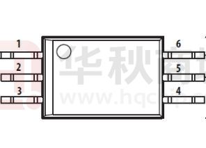
PIN CONFIGURATION
Package
Pin Configuration (Top View)
1
6
2
5
3
4
ANODE
Stretched SO6
VCC
NC
VOUT
CATHODE
5
VEE
PIN DESCRIPTION
No.
Pin
Description
1
ANODE
Anode
2
NC
No Connection
3
CATHODE
Cathode
4
VEE
Negative Power Supply Rail
5
VOUT
Gate Drive Output
6
VCC
Positive Power Supply Rail
6
FUNCTIONAL BLOCK DIAGRAM
ISOLATION
ANODE
1
2
CATHODE
3
2
VCC
5
2
VOUT
4
2
VEE
UVLO
e
BARRIER
NC
6
FIG. 2 SLM341
ORDERING INFORMATION
Order Part No.
Package
QTY
SLM341CK-DG
SO6, Pb-Free
1000/Reel
Sillumin Semiconductor Co., Ltd. – www.sillumin.com
Rev01, July 2020
2
�SLM341
Preliminary Datasheet
PACKAGE CASE OUTLINES
Sillumin Semiconductor Co., Ltd. – www.sillumin.com
Rev01, July 2020
3
�SLM341
Preliminary Datasheet
Revision History
Sillumin Semiconductor Co., Ltd. – www.sillumin.com
Rev01, July 2020
4
�
很抱歉,暂时无法提供与“SLM341CK-DG”相匹配的价格&库存,您可以联系我们找货
免费人工找货