switches
Switch Engineering Catalogue No. 7.2
APEM.COM
�Company
SINCE 1938
DANISH DESIGN
IN-HOUSE R&D AND PRODUCTION
IN-LINE QUALITY CONTROL
Since its foundation in 1938, MEC has been making state-of the-art
electromechanical components.
Located in a suburb of Copenhagen, Denmark, MEC has earned a
reputation as one of the leading European manufacturers of high
performance tactile switches.
A wealth of know-how has been built up over the years for the
benefit of innovative product development and custom solutions.
Despite the trend of outsourcing it has been MEC policy to maintain
a high degree of vertical integration that enables us to react
promptly to customer requests. 98% of all the parts used in MEC
switches are produced in-house.
With 100% in-line inspection, tight tolerance on all parts and use
of only quality materials we position ourselves to reach the highest
achievable level within high performance tactile switches.
The vertical integration combined with a strong R&D facility enables
us to provide custom designs from conception to completion.
To be part of a sustainable industrialised world environmental
consciousness is crucial. At MEC we have substituted materials
to more environmental-friendly alternatives and are recycling as
much as possible. Legal authorities are auditing our environmental
management system regularly and confirming that our goal is being
reached. All MEC products are RoHS compatible.
MEC have a well established global distribution network that
provides a presence in all parts of the world where electronic
manufacturing takes place. Through close contact and continuous
product training offered to our distributors we maintain a highly
qualified and responsive global distribution network.
2
�Table of content
Selection guide for caps and accessories . . . . . 4
Selection guide for switches . . . . . . . . . . . . . 36
multimec® caps
multimec® switches
Introduction to Caps . . . . . . . . . . . . . . . . . 5
Introduction to Switches . . . . . . . . . . . . . . . 37
Introduction to Illumination . . . . . . . . . . . . . 6
5 series switches . . . . . . . . . . . . . . . . . . . . 38
Introduction to Panel Sealed and Foil solutions . . 7
3C/3E series switches . . . . . . . . . . . . . . . . . 40
Technical information . . . . . . . . . . . . . . . . . . . 41
1A/1H/1M/1ZA . . . . . . . . . . . . . . . . . . . . . 8
Technical Information - spacing . . . . . . . . . . . . . 42
1B/1C+2C/2D . . . . . . . . . . . . . . . . . . . . . . 9
Technical Information - module . . . . . . . . . . . . . 43
1DS/1ES/1FS . . . . . . . . . . . . . . . . . . . . . . . 10
Technical Specifications - 5 series . . . . . . . . . . . . 44
1GAS/1GCS . . . . . . . . . . . . . . . . . . . . . . . 11
Technical Specifications - 3 series . . . . . . . . . . . . 45
1JS . . . . . . . . . . . . . . . . . . . . . . . . . . . . . 12
Technical Specifications - LEDs . . . . . . . . . . . . . . 46
1KS/1KBS/1KCS . . . . . . . . . . . . . . . . . . . . . 13
1NS . . . . . . . . . . . . . . . . . . . . . . . . . . . . 14
1PS/1QS/1RS . . . . . . . . . . . . . . . . . . . . . . 15
1SS/1IS/1LS . . . . . . . . . . . . . . . . . . . . . . . . 16
1TS/1US/1VS + +1TW/1UW/1VW . . . . . . . . . 17
1WAS/1WDS/1WPS . . . . . . . . . . . . . . . . . . 18
1XS . . . . . . . . . . . . . . . . . . . . . . . . . . . . 19
foilmec™ 1YS . . . . . . . . . . . . . . . . . . . . . . 20
navimec™ 1ZCS/1ZB . . . . . . . . . . . . . . . . . . 21
navimec™ module . . . . . . . . . . . . . . . . . . . 22
controlmec™ 1ZW . . . . . . . . . . . . . . . . . . . 23
controlmec™ 1Z . . . . . . . . . . . . . . . . . . . . . 24
controlmec™ module . . . . . . . . . . . . . . . . . 25
10R/10RF/10RM . . . . . . . . . . . . . . . . . . . . 26
10Q/10QM . . . . . . . . . . . . . . . . . . . . . . . 27
varimec™ . . . . . . . . . . . . . . . . . . . . . . . . . 30
aquamec™ . . . . . . . . . . . . . . . . . . . . . . . . 32
Extender 2SS . . . . . . . . . . . . . . . . . . . . . . 33
Legends . . . . . . . . . . . . . . . . . . . . . . . . . 34
unimec™ caps and switches
Introduction to unimec™ . . . . . . . . . . . . . . . 47
16324-16326 . . . . . . . . . . . . . . . . . . . . . . 48
16310-16315 . . . . . . . . . . . . . . . . . . . . . . . 49
16300/16700/16800 . . . . . . . . . . . . . . . . . . 50
Legends . . . . . . . . . . . . . . . . . . . . . . . . . 51
unimec™switches . . . . . . . . . . . . . . . . . . . . 52
vario™ support . . . . . . . . . . . . . . . . . . . . . . . 53
unimec™ with multimec® caps . . . . . . . . . . . . . . 54
Technical Specifications . . . . . . . . . . . . . . . . . . 55
Custom
Custom products . . . . . . . . . . . . . . . . . . . . 56
Custom products . . . . . . . . . . . . . . . . . . . . 57
General
Applications . . . . . . . . . . . . . . . . . . . . . . . . . 28
Solid Colours . . . . . . . . . . . . . . . . . . . . . . . . 58
Usage Guidelines . . . . . . . . . . . . . . . . . . . . . . 59
3
�Caps and accessories series
Selection guide
NON-ILLUMINATED
1JS
Ø9.6mm
h=10.4mm
1DS
Ø9.6mm
h=14.9mm
1GAS
Ø11mm
h=12.5mm
1IS
Ø6.5mm
h=10.4 22.5mm
varimec™ round
Ø5.2; 7.8;11.6mm
h=10.4-22.5mm
*for 3E
1US
Ø10.6mm
h=14.9mm
1ZCS
Ø14.3mm
h=11.7mm
1GCS
Ø15mm
h=12.5mm
1LS
Ø6.5mm
h=12.0mm22.5mm
1Z
Ø29.5mm
h=12.0mm
1ZW
Ø29.5mm
h=12.3mm
aquamec
Ø10.6mm
h from front
panel=14.3mm
h=24.2-27.2mm
1ES
Ø9.6mm
h=14.9mm
10R/10RF
Ø30mm
h=12.6/11.0mm
10RM16
Ø30mm
h=11.0mm
navimec
Ø34.25mm
h=11.7/
12.2mm
1FS
Ø9.6mm
h=14.9mm
1ZA
18.65x10.1mm
h=12.2mm
1PS
12.5x6.5mm
h=15.7mm
1XS
7.4x9.4mm
h=18.5mm
1QS
12.5x6.5mm
h=15.7mm
1RS
12.5x6.5mm
h=15.7mm
1M
25.0x10.1mm
h=12.2mm
1A
12.5x10.1mm
h=12.2mm
1TS
10.6x10.6mm
h=14.9mm
1H
12.5x10.1mm
h=12.2mm
1C + 2C/2D
15.1x15.1mm
h=12.2mm
varimec™ square
5.2x5.2; 7.8x7.8;
11.6x11.6mm
h=10.4-22.5mm
*for 3E
1B + 2C/2D
15.1x15.1mm
h=12.2mm
1KS
14.3x14.3mm
h=19.1mm
2K
17.75x17.75mm
1KBS
14.3x14.3mm
h=20.2mm
unimec™ 16300
6.0x12.3mm
h=16.9mm
10Q
22x22mm
h=11.0mm
10QM16
22x22mm
h=11.0mm
1KCS
14.3x14.3mm
h=20.1mm
OTHER
unimec™ 16700
14.9x14.9mm
h=14.6mm
1YS
15x15mm
h=12.5mm
*for 5E
2SS
extender for
5G snap on
caps
h=5-10mm
1NS
Ø9.6/☐4.9mm
h=14.9mm
1VS
10.6x13.25mm
h=14.9mm
1ZB
90o
R=17.5mm
h=12.2mm
1TW/1UW/1VW
sealing for
1TS/1US/
/1VS
1WAS
6.5x12.5mm
h=14.9mm
1WDS
8.0x15.2mm
h=14.9mm
1WPS
6.5x12.5mm
h=15.7mm
*Caps are for 5G if not otherwise specified
4
ILLUMINATED
1SS
Ø6.5mm
h=8.0 22.5mm
*for 5E
ROUND
SQUARE/RECTANGULAR
NON-ILLUMINATED & ILLUMINATED
�multimec®
Caps & Accessories for the 5 series switches
CAPS
MANY OPTIONS REGARDING:
SHAPE, SIZE, HEIGHT, COLOUR AND ILLUMINATON
SOLUTIONS:
NAVIMEC™, CONTROLMEC™, FOILMEC™, VARIMEC™, AQUAMEC™
MEC has a wide range of caps for the multimec® switch series. There
are many cap series including navimec™, controlmec™ foilmec™ and
aquamec™ for multimec® 5 series switches, and varimec™ that is still
for the 3 series switches.
18 solid colours and 6 transparent colours
Overall height varies from 8.0 mm to 27.2 mm
5
�multimec®
Caps & Accessories for the 5 series switches
ILLUMINATION
SINGLE- OR BI-COLOUR
MANY OPTIONS IN LED, CAP AND LENS COLOUR
5 LED colour options available: blue, green, yellow, white and red.
Bi-colour combination can be made with any two LED colours.
Illumination can be full, dot, rectangular or legend.
6
�multimec®
Caps & Accessories for the 5 series switches
MEC cap range includes options for the front panel sealing. We have
designed cap options for outdoor, dusty and humid applications switch solutions that can endure a rough environment.
PANEL SEALED SOLUTIONS
CONTROLMEC™ 1ZW
PANEL SEALED 1TS/1US/1VS
PANEL SEALED 10R & 10Q SERIES
AQUAMEC™
CAPS FOR FOIL OVERLAY
FOILMEC™ + 1GAS/1GCS + 1JS
7
�0,8
0,3
Min. 10,16
Max 12,5
Min. 10,16Min. 10,16
Max 12,5 Max 12,5
0,8
7,62
7,62
8 - 108 - 10
0,8
8 - 10
10
88--10
0,3
7,62
10,1
10,1 10,1
10,1
10,1
10,1
10,1
10,1
10,1
0,3
7,62
7,62
7,62
■■ Rectangular caps
■■ Rocker-action pushbutton cap
■■ 12.5 mm x 10.1 mm; 18.65 mm x 10.1 mm; 25.0 mm x 10.1 mm
■■ h =12.2 mm
■■ Material: ABS/polycarbonate
18,65 18,65
18,65
12,5
12,5
12,5
■■ Temp. Range:
•• Solid cap: -40/+65°C
•• Transparent cap: -40/+85°C
5GTxx+1H ■■ Panel cut-out: 1A/1H-13.0 x 10.5, 1M-25.7 x 10.5, 1ZA-19.4x10.5
5GT+1ZA
12,5
12,5
5GTxx+1H
5GTxx+1H
1A
5GT+1ZA
5GTxx+1H5GTxx+1H
5GTxx+1H
5GSxx+1A
5GSxx+1A
5GSxx+1A
5GT+1ZA 5GT+1ZA
5GS+1M
5GT+1ZA
All dimensions in mm
5GS+1M 5GS+1M
Tolerances
-/+0.2mm
1A
1A
1A
DIMENSIONS
7,62
10,1
25,0
18,65
18,65
25,0
0,8
7,62
7,62
8 - 108 - 10
8 - 10
8 - 10
0,8
7,62
7,62
10,1 10,1
10,1
10,1
1ZA
1ZA
10,1
10,110,1
1ZA
8 - 10
12,2 12,2
12,2
14,0
0,8
7,62
0,8
0,8
0,8
8 - 10
12,2
12,2
12,2
0,3 0,3
8 - 10
0,3
8 - 10 8 - 10
12,212,2
12,2
10,1
25,0
1A
Min. 10,16
Max. 12,5
7,62
10,1
1H
1M
1M
03 grey
09 black
1A
1A
1A
18,65
7,62
5GT+1ZA
1A
10,1
10,1
1M
1H
5GT+1ZA
5GS+1M
Lens 1H
0,8
14,0
5GTxx+1H
Colour code 1H
0,8
0,3
8 - 10
12,2
02 blue
22 green
5GSxx+1A5GSxx+1A
42 yellow
61 white
82 red
2242 green/yellow
8222 red/green
8242 red/yellow
Cap
8 - 10
12,2
8 - 10
12,2
10,1
8 - 10
12,2
0,3
12,5
5GTxx+1H
5GT+1A
8 - 10
8 - 10
12,2
3
8 - 10
12,2
10,1
5GSxx+1A
7,62
Min. 10,16
Max. 12,5
7,62
5GT+1A
+
0,8
0,8
14,0
LED
0,3
20
35
5GSxx+1A
65
Q*
0,8
5GT+1ZA
18,65
14,0
0,3 0,8 0,37,62 14,0
Min. 10,16
7,62 Min. 10,16
7,62
Max. 12,5 Max. 12,5
18,65
5GSxx+1A
5GSxx+1A
12,5
Actuation force
5GS+1M
TH9 through-hole
SH9 surface mount
5GS+1M 5GS+1M
18,65
12,5
7,62
Min. 10,16
Max 12,5
18,65
10,1
12,5
12,5
10,1
5 G
0,8
0,3
Min. 10,16
Max. 12,5
5GTxx+1H
12,5
5GT+1ZA
0,3
10,1
10,1
4,4
ILLUMINATED – HOW TO ORDER
Min. 10,16
Max. 12,5
Min. 10,16
Max. 12,5
7,62
Min. 10,16
Max. 12,5
12,5
0,3
0,8
10,1
8 - 10
0,3
5GT+1A
7,62
1H
1H
1H
0,8
Min. 10,16
7,62
Max. 12,5
7,62
SMD + 1M
0,3
5GTxx+1H
7,62
Mounting
0,8 0,3
0,8
8 - 10 8 - 10
12,2
12,2
0,3 Min. 10,16
Max. 12,5
7,62
12,5
Switch
0,8
0,3
10,1
10,1
10,110,1
10,1 10,1
0,3
0,8
Min. 10,16
Max 12,5
12,5
12,5
TH + 1ZA
Min.
7,6210,16Min. 10,16
Max. 12,5 Max. 12,5
7,62
0,3
12,50 12,50
12,50
8 - 10
8 - 10
12,2
0,8
0,3
0,8
7,62
7,62
0,8
0,8
0,8
0,8
7,62
5GT+1A
0,3
14,0 14,0
14,0Min. 10,16
Max. 12,5
7,62 Min. 7,62
10,16
Min. 10,16
Max. 12,5
Max. 12,5
10
88 -- 10
8 - 10
8 - 10
12,212,2
12,2
12,2
12,2
8 - 12,2
10
8 - 10
0,3
TH w/LED + 1H
12,2
0,30,8
0,3
0,3
0,3
SMD w/LED + 1A
Colour code 1A
16 frosted white
1ZA
1 transparent
2 green
4 yellow
6 frosted white
8 red
1A
1A
5GSxx+1A
12,50
0,3
NON-ILLUMINATED– HOW TO ORDER
0,3
0,8
7,62
12,50
14,0
12,50
8 - 10 8 - 10
8 - 10
8 - 10
10,1
10,1
12,50
5GSxx+1A
0,8
0,8
8 - 10
7,62
7,62
1ZA
12,50
Cap
7,62
Colour code 1A/1M
1A
18,65
1A
1M
1A
1H
8 - 108 - 10
12,2 12,2
8 - 10
10,1 10,1
12,2
14,0
14,0
7,62
0,8
1A
1H
1ZA
1H
1ZA
8 - 10
7,62
7,62
20
20Q
35
65
10,1 10,1
12,2
0,8
0,8
0,3 0,3
14,0
14,0
0,3
5GSxx+1A
1ZA
0,8
7,62
25,0
10,1
10,1
1M
1M
1ZA
1M
12,50
25,0
00 blue
02 green
03 grey
04 yellow
06 white
08 red
09 black
1ZA
Colours 1ZA:
1ZA
1ZA
03 grey
06 white
09 black
30 ultra blue
40 dusty blue
1M
421Maqua blue
1M
50 metal dark blue
53 metal light grey
57 metal dark grey
58 metal bordeaux
1M
8
1H
7,62
12,50
+
5GSxx+1A
TH9
through-hole
12,50
12,50
SH9 surface mount
8 - 108 - 10
0,3 0,3
5GS+1M
14,0
25,0
Actuation force
12,50
12,2 12,2
,0
12,5
10,1
10,1
10,1
5 G
5GS+1M
5GS+1M
10,110,110,1
Mounting
10,1
Switch
12,5
25,0
1H
0,8
7,62
0,8
Min.18,65
10,16
Max. 12,5
18,65
7,62
Min.12,5
10,16
Max. 12,5
12,5
1H
1M
1H
10,1
7,62
12,2
14,0
14,0
8 - 10
12,2 12,2
7,62
7,62 14,0
0,8
1H
7,62
7,62
10,1 10,112,2
8 - 10
8 - 10
7,62
0,8
10,1
0,3
0,8
12,2
0,3
0,3
7,62
14,0
0,8
Min. 10,16
Max. 12,5
Min. 10,16
Max. 12,5
0,8
10,1
Min.12,5
10,16
Max 12,5
12,5
14,0
10,1 10,1 12,2
0,3
14,0
0,8
5GT+1ZA
0,3
0,3
12,2
7,62
7,62
12,2
8 - 108 - 10
0,8
0,8
8 - 10
8 - 10
0,3
Min. 10,16
Max. 12,5
Min. 10,16
Max. 12,5
*For an illuminated quiet 2.0N switch add Q 0,8
0,8
0,8
14,0
0,8
0,8
to the end of the
switch
part
number.
7,62
7,62
7,62
0,3
0,3
8 - 10
7,62
5GTxx+1H
0,3 8 - 10
0,3
0,3 0,3
8 - 10
12,2
0,8
0,8
8 - 10
,0
8 - 108 - 10
12,2
Min. 10,16
Max 12,5
Min. 10,16
Max 12,5
10,1 10,1 12,2
0,3
0,3
12,2
5GT+1A
12,2 12,2
12,212,2
12,2 12,2
25,0
8 - 10
8 - 10
8
0,8
0,8
0,8
Min.
Min. 10,16
Min. 10,16
10,16
Max.
Max. 12,5
Max. 12,5
12,5
7,62
7,62
12,2 12,2
0,3
0,3
0,3
7,62
5G + 1A/1H/1M/1ZA
12,2
0,8
0,8
0,8
n.
n. 10,16
10,16
ax.
ax. 12,5
12,5
8 - 10
12,2
10
88 -- 10
8 - 10
12,2
12,2
12,2
Rocker-action pushbutton caps
12,2
12,2
multimec®
Ordering example:
5GSH93582 + 1H098 with illumination OR 5GTH965 + 1ZA57 without illumination OR *5GTH92001Q (illuminated quiet version).
Please see colour codes, updates of products and changes of specifications on www.apem.com
1ZA
1M
�multimec®
5GT+1B+2C
5GS+1B+2D
5GS+1B+2D
5GS+1B+2D
12,2
12,2
8
8
8
12,2
12,2
8
8
15,1
9,5
15,1
15,1
15,1
9,5
15,1
9,5
9,5
9,5
15,1
9,5
3
3
15,1
3
9,5
0,3
0,3
9,5
15,1
3
15,1
33
9,59,5
15,1
12,6
1C
1C
2 C
Colour
code
2C
2C
2C
8
12,2
1B
2 D
3
7,62
12,2
9,5
2D
Colour
code
8
2C
2D
8
9,5
8
15,1
1C
1C
7,62
7,62
9,5
3
12,6
12,6
2C
Lens
1C
1B
7,62 1B
5GSxx+1B+2D
2D
2D
3
Bezel
12,2
0,3
9,5
14,0
+
0,8
7,62
8
Colour
code
2C
3
9,5
2 D
2C
Colour
code
2D
Lens
8
15,1
2D
2 C
15,1
Colour
12,6
code
2C
1C
1C
8
3
12,6
9,5
15,1
1C
12,6
3
15,1
8
12,6
1B
8
0,3
8
0,3
15,1
15,1
12,2
8
8
0,3
8
8
12,2
12,2
8
8
8
8
15,1
9,5
12,2
3
9,5
12,28
12,2
12,2 8
8
3
15,1
15,1
15,1
9,5
3
3
9,5
8
9,5
15,1
15,1
8
12,2
12,2
8
3
1 B
Solid
12,6
colour
0,3
8
12,2
15,1
3
9,5
12,2
9,5
9,5
8
15,1
8
9,5
+
1B
15,1
8
Cap
7,62
15,1
1B
Bezel
0,8
15,1
8
0,8
8
9,5
8
12,2
12,2
9,5
9,5
3
8
15,1
12,6
12,6
15,1
+
0,3
0,3
0,3
8
8
8
12,2
12,2
8
8
8 12,2
8
12,2
15,1
15,1
9,5
15,1 2,8
9,5
9,5
8
12,6
1B
8
12,6
7,62
12,6
0,8
14,0
15,1
7,62
1B
7,62
2D
3
2D
9,5
3
15,1
8
Solid caps 1B
00 blue
06 white
02 green
08 red
03 grey
09 black
04 yellow
12,6
12,6
4,4
9,5
15,1
9,5
15,1
1B
7,62
14,0
14,0
15,1
12,6
7,62
0,8 14,0
8
12,6
12,6
5GTxx+1C+2C
5GSxx+1B+2D
0,3
12,6
Solid caps 1C
03 grey
08 red
09 black
1C
2C
8
12,2
8
7,62
7,62
0,8
14,0
9,5
3
15,1
15,1
9,5
4,4
12,6
15,1
15,1
4,4
12,6
15,1
COLOUR CODES
Transparent caps
16 frosted white
5GSxx+1B+2D
0,3
7,62
15,1
12,6
8
0,8
8
5GSxx+1B+2D
15,1
7,62
7,62
0,8
12,6
12,6
15,1
8
12,2
Min. 10,16
Max. 12,5
0,8
0,8
0,8
0,8
14,0
Min. 10,16
Max. 12,5
8
7,62
Min. 10,16
Max. 12,5
0,8
Min. 10,16
Max. 12,5
8
12,2
Min. 10,16
Max. 12,5
14,0
0,8
9,5
3
15,1
3
15,1
15,1
TH9 through-hole
20
SH9 surface mount12,6 20Q
35
65
0,3
0,3
0,3
3
15,1
12,6
5GT+1B+2C
12,2
12,6
15,1
9,5
15,1
9,5
3
9,5
8
12,6
7,62
5GTxx+1C+2C
Actuation8force
5GTxx+1C+2C
5GTxx+1C+2C
4,4
7,62
8
4,4
1 C
12,6
15,1
15,1
15,1
0,3
12,6
4,4
15,1
Mounting
4,4
15,1
5GT+1B+2C
0,8
14,0
15,1
Cap
14,0
0,8
7,62
15,1
3
9,5
9,5
2,8
9,5
9,5
3
15,1
3
15,1
15,1
15,1
4,4 12,6
12,6
15,1
12,6
12,6
0,3
5GT+1B+2C
0,8
7,62
0,8
8
14,0
7,62
0,3
9,5
3
15,1
4,4
12,6
0,8
15,1
8
8
7,62
7,62
7,62
02 blue
Solid
Colour
Lens
colour5GSxx+1B+2D
22 green
code
5GSxx+1B+2D
5GSxx+1B+2D
42
yellow
61 white
82 red
1 B
0,8
2242 green/yellow
7,62
TransColour
8222 red/green
parent
code 0,8
8242 red/yellow
15,1
14,0
0,8
7,62
0,8
12,2
3
3
8
0,3
0,3
Min. 10,16
Max. 12,5
9,5
15,1
12,2
12,2
12,6
0,3
12,6
Min. 10,16
Max. 12,5
15,1
9,5
4,4
14,0
14,0
7,62
0,8
14,0
5GSxx+1B+2D
5GT+1B+2C
7,62
15,1
NON-ILLUMINATED–
HOW TO ORDER
Switch
12,2
0,3
3
12,2
8
9,5
3
12,2
0,3
0,3
15,1
8
8
8
0,3
7,62
7,62
15,1
7,62
15,1
14,0
12,2
8
12,2
8
0,3
0,8
15,1
12,6
+
0,8
8
5GSxx+1B+2D
15,1
12,2
12,2
12,2
12,2
8
0,3
0,3
8
15,1
5GSxx+1B+2D
Min. 10,16
Max. 12,5
14,0
0,3
7,62
0,8
14,0
12,2
9,5
0,3
15,1
0,8
0,8
12,6
5GSxx+1
4,4
5GSxx+1B+2D
Min. 10,16
Max. 12,55GT+1B+2C
15,1
5GTxx+1C+2C
7,62
0,8
5GSxx+1B+2D
12,2
8
5GS+1B+2D
14,0
12,6
5GSxx+1B+2D 5GSxx+1B+2D
5GTxx+1C+2C
5GS+1B+2D
Min. 10,16
Max. 12,5
3
4,4
12,6
7,62
15,1
Min. 10,16
an
illuminated quiet0,82.0N switch add7,62Q
0,8Min. 10,16*For 0,8
Max.
15,112,5
7,62
Max. 12,5to the end of the switch part number.
7,62
7,62
15,1
Min. 10,16
Max.15,1
12,5
12,6
LED
3
12,2
15,1
20
35
65
Q*
15,1
3
9,5
15,1
0,3
7,62
7,62
0,8
12,6
0,8
0,8
0,3
12,6
Actuation force
12,6
7,62
12,6
5GTxx+1C+2C
0,8
Min. 10,16
Max. 12,5
Min. 10,16
Max. 12,5
5GTxx+1C+2C
0,8
0,8
4,4
12,6
12,6
12,6
12,6
12,6 0,8
7,62
9,5
3
9,5
15,1
15,1
0,3
4,4
5GS+1B+2D
TH9 through-hole
5GTxx+1C+2C
SH9 surface mount
15,1
SMD w/LED 1B+2D
0,8
15,1
0,8
0,8
4,4
12,6
5GT+1B+2C
5GTxx+1C+2C
Min. 10,16
Max. 12,5
7,620,8
0,3
0,8
Min. 10,16
7,62
Max. 12,5
Min. 10,16
7,62
Max. 12,5
15,1
9,5 15,1
15,1
12,6
5GT+1B+2C
Min. 10,16
Max. 12,5
5GTxx+1C+2C
15,1
12,6
9,5
5 G
12,6
15,1
38
15,1
9,5
15,1
14,0
8
8
7,62
5GTxx+1C+2C
0,3
7,62
0,8
0,3
15,1
15,1
0,3
12,2
14,0
0,3
0,8
8
Min. 10,16
Max. 12,5
5GTxx+1C+2C
15,1
15,1
9,5
0,3
8
12,2
15,1
0,3
15,1
15,1
15,1
12,6
Mounting
15,1
7,6
Min.Min.
10,16
10,16
Max.
12,512,5
Max.
15,1
5GT+1B+2C
12,2
3
15,1
9,5
9,5
15,1
3
9,5
3
15,1
15,1
12,6
ILLUMINATED
– HOW TO ORDER
5 G
0,8
5GS+1B+2D
5GS+1B+2D
0,8
0,3
7,620,3
0,3
15,1
5GT+1B+2C
8
12,2
8
15,1
5GTxx+1C+2C
GS+1B+2D
5GT+1B+2C
Min. 10,16
0,30,8
0,3
Max. 12,5 Min. 10,16
Max.7,62
12,5
15,1
12,6
15,1
8
12,6
5GS+1B+2D
8
0,8
Min. 10,16
Max. 12,5
12,6
12,6
12,6
0,3 Min. 10,16
7,62
Max.
Min. 12,5
10,16
Min. 10,16
Max. 12,5
Max. 12,5
7,62
14,0
15,1
12,6
12,2
12,2
12,2
12,2
8
0,3
0,8
0,3
0,8
Min. 10,16
Max. 12,50,3
815,1
0,3
8
9,5
15,1
8
8
14,0
Switch
8
TH w/LED 1C+2C
0,3
7,62
12,6
8
15,1
5GTxx+1C+2C 5GTxx+1C+2C
15,1
8
15,1
TH 1B+2C
7,62
15,1
15,1
0,3
Max. 12,5
7,62
7,62
7,62
3
3
15,1
5GT+1B+2C
8 12,2
0,3
8
12,2
14,0
7,62
14,0
14,0
14,0
Min. 10,16
0,8
0,8
0,8
Tolerances -/+0.2mm
5GT+1B+2C
SMD 1B+2D
0,8
0,3
0,3
8
5GS+1B+2D
5GS+1B+2D
DIMENSIONS
0,8
7,62
15,1
9,5
15,1
15,1
15,1
12,2
0,3
All dimensions in mm
5GS+1B+2D
0,3
0,8
7,62
8
12,2
0,3
0,8
14,0
■■ Rectangular caps; square solution
■■ Rocker-action pushbutton cap
15,1
■■ 15.1 mm x 15.1 mm 0,8
8
Min. 10,16
7,62
■■ h12,5=12.2 mm
Max.
■■ Material: ABS/polycarbonate
■■ Temp. Range:
•• Solid cap and bezel:
0,8 -40/+65°C
12,6
14,0
7,62
•• Transparent cap: -40/+85°C
■■ Panel cut-out: 1B/1C+2C/2D-15.5 x 15.5
5G + 1B/1C+2C/2D
12,2
12,2
0,3
0,3
14,0
5GT+1B+2C
5
Award winning design of rocker-action cap solution
S+1B+2D
8
5GS+1B+2D
12,2
8
5GS+1B+2D
0,8
14,0
Solid colours 2C & 2D:
00 blue
03 grey
06 white
08 red
09 black
Lenses
1 transparent
2 green
4 yellow
6 frosted white
8 red
7,62
Ordering example:
5GTH93561+1C031+2C09 with illumination OR 5GSH965+1B08+2D081 without illumination OR *5GSH92001Q (illuminated quiet version)
Please see colour codes, updates of products and changes of specifications on www.apem.com
15,1
8
9,5
15,1
3
2D
12,6
9
�multimec®
Round cap with soft edges
5G + 1DS/1ES/1FS
8,2
0,3
14,0
11,0
0,8
7,62
All dimensions in mm
8,2
0,8
14,9
9,6
0,8
14,9
9,6
■■ Round caps
■■ Ø9.6 mm
■■ h =14.9 mm
■■ Material: ABS/polycarbonate
■■ Temp. Range:
11,0
•• Solid cap: -40/+65°C
•• Transparent cap :-40/+85°C
■■ Panel cut-out: 1DS/1ES/1FS-Ø10.0
0,8
0,3
Min 10,16
Max 12,5
7,62
Tolerances -/+0.2mm
DIMENSIONS
7.62
10
ø 0.9
4
0,8
14,0
7,62
7,62
0.3
Min 10.16 Min 10.16
Max 12.5 Max 12.5
7,62
0.8
0.3
8.2
0.8
7.62
7.62
10,16
Max 10,3
10,16
-2
-2
4
4+3
1
Max 10,3
7,6
3
+3
10.3
8.2
ø 11.0
0.8
14.9
0,8
Max 10,3
Max 10,3
ø 11.0
ø 9.6
8,2
8,2 0,8
0,8
8,2
14,9
0,8
0,3
10
1
0,8
ø 9.6
1
10.3
Ø0,9
7,62
10.16
-2
14,0
11,0
7,62
14,0
TH w/LED + 1FS
11,0
9,6
11,0
14,9
7,62 7.62
10
Max 10,3
0,3
0,3
0.8
9,6
10
Min 10.16
Min
10,16
Max 12.5
Max 12,5
8.2
0,8
8,2
0,8
0,3
0.3
9,6
0.8
14.9
14,9
11,0ø 11.0
0.8
14.9
SMD w/LED + 1ES
9,6
ø 9.6
14,9
TH + 1DS
+3
Ø0,9
ILLUMINATED – HOW TO ORDER
Switch
Mounting
Actuation force
LED
Cap
Colour code
Lens
1ES
00 blue
02 green
03 grey
04 yellow
06 white
08 red
09 black
1 transparent
2 green
4 yellow
6 frosted white
8 red
+
5 G
TH9 through-hole
SH9 surface mount
Max 10,3
20
35
65
Q*
02 blue
22 green
42 yellow
61 white
82 red
2242 green/yellow
8222 red/green
8242 red/yellow
1FS
1ES
1ES
1FS
1FS
1DS
11 transparent
16 frosted white
*For an illuminated quiet 2.0N switch add Q
to the end of the switch part number.
NON-ILLUMINATED– HOW TO ORDER
Switch
Mounting
Actuation force
Cap
Colour code
1DS
00 blue
02 green
03 grey
04 yellow
06 white
08 red
09 black
1ES
+
5 G
TH9 through-hole
SH9 surface mount
20
20Q
35
65
1ES
30 ultra blue
40 dusty blue
42 aqua blue
32 mint green
33 tele grey
34 melon
38 noble red
Ordering example:
5GTH935+1DS06 without illumination OR 5GSH96561+1FS096R13509 with illumination OR *5GSH92042Q (illuminated quiet version)
Please see colour codes, updates of products and changes of specifications on www.apem.com
1FS
10
1FS
50 metal dark blue
53 metal light grey
57 metal dark grey
58 metal bordeaux
�5GT+1GCS 5GT+1GCS
5GT+1GCS
5GS+1GAS
5GS+1GAS
5GT+1GCS
5GT+1GCS
Flat cap can be used with foil overlay
12,5
12,5
12,5
5GTxx+1GCS
5GTxx+1GCS
15
0,8
7,62 0,8
0,8
0,310,16
0,3
0,3 Min.
7,62
0,3
0,3
7,62
7,62
Min. 10,16
Max. 12,5
0,8
Min. 10,16
Min. 10,16
Min. 10,16 Min. 10,16
Max. 12,5
7,62
Max. 12,5
Max. 12,5
7,62
Max. 12,5
Max. 12,5
0,8
0,8
7,62
0,8
0,8
12,5
0,3
0,3
0,3
Min.
0,8
0,3 10,16 Min. 10,16
10,16
Max. 12,5 Min.
Max. 12,5
0,3 0,8 0,3
0,8 0,8 7,62 Min. 10,16
Max. 12,5
10,16
Min. 10,16Min.
Max.
12,5
7,62Max. 12,5
Max. 12,5
7,62
7,62
7,62
12,5
12,5
12,5
12,5
12,5
0,3
12,5
12,5
12,5
12,5
12,5
0,8
12,5
15
15
12,5
0,3
0,3
14,0
14,0
0,3
0,3
5GT+1GCS
THw/LED
15 15 +1GCS
15
15
15 15
15
12,5
0,8
10 10,3
Max
10
10
15
12,5
12,5
12,5
12,5
0,3
0,3
7,62
TH + 1GCS
15
11
7,62 0,8
0,8
0,8
14,0
7,62
7,62 7,62
7,62
14,0
14,0
0,8
7,
7,
7,62
7,62
0,87,62
0,8
0,8
0,8
7,62
7,62 7,62
7,62
7,62
Max 10,3
Max 10,3
Max 10,3
Max 10,3
10
10 10
10
12,5
12,5
10
10
11
11
1010
10
10
0,3
0,3
0,3
14,0
12,5
12,5
11
14,0
0,8
0,8
0,87,62
0,8
5GTxx+1GCS5GTxx+1GCS
5GTxx+1GCS
5GT+1GCS
5GT+1GCS
5GT+1GCS
5GT+1GCS 5GT+1GCS
5GSxx+1GAS
5GSxx+1GAS
SMD w/LED
+ 1GAS
11
0,3
0,3
Min. 10,16 Min. 10,16
10,16
0,3
Max. 12,5 Min.
Max. 12,5
Max. 12,5
Min. 10,16Min. 10,16
Max. 12,5Max. 12,5
5GT+1GCS
12,5
11
11
11 11
0,8
0,3
7,62
7,62
0,8
0,3
7,62
7,62
5GSxx+1GAS5GSxx+1GAS
5GSxx+1GAS
11
14,0
14,0 14,0 0,8
0,8
Tolerances
-/+0.2mm
5GS+1GAS
5GS+1GAS
DIMENSIONS
5GS+1GAS
5GS+1GAS
5GS+1GAS 5GS+1GAS
14,0
0,8
0,8
7,62
0,8
10
10
All dimensions
5GS+1GASin mm
11
0,8
1010
10
0,3
0,3
0,3
0,3
0,3
■■ Round caps
14,0
14,0
14,0
■■ Excellent option for foil14,0
overlay
14,0
■■ Ø11 mm; Ø15 mm
10
10
10
■■ h =12.5 mm
10
10
■■ Material: polyamide
■■ Temp. Range:
•• Solid cap: -40/+160°C
•• Transparent cap: -40/+85°C
■■ Panel cut-out: 1GAS/1GCS-Ø11.4; Ø15.4
SMD + 1GAS
15
15
15
15
11
11
5G + 1GAS/1GCS
15
11
11
12,5
11
ILLUMINATED – HOW TO ORDER
Switch
Mounting
Actuation force
LED
Cap transparent colour
1GAS
Colour code
+
5 G
1GAS
14,0
14,0 0,8
14,0 14,0
0,8
7,62
0,8
0,8
7,62
7,62
7,62
7,62 7,62
14,0
Max. 12,5
0,8
Max. 12,5
Min.
Max.10,16
12,5
Max. 12,5 7,62
Max. 12,5
Max. 12,5
7,62
7,62
7,62
7,62 7,62
5GTxx+1GCS
11 transparent
16 frosted white
0,3
7,62
Max 10,3
Max
Max
10,3
Max 10,3
10,3
12,5
12,5
12,5
15
12,5
12,5
12,5
12,5
12,5
12,5
0,8
0,8
0,3
0,3
0,3
14,0
12,5
11
5GSxx+1GAS
5GTxx+1GCS
5GTxx+1GCS
5GTxx+1GCS
5GTxx+1GCS
5GTxx+1GCS5GTxx+1GCS
02 blue
1GAS
22 green
42 yellow
15
15
15 15
15
15
61 white
82 red
1GCS
2242 green/yellow
8222 red/green
0,3
0,8
0,3 0,3
0,3
0,3
0,8 0,8
0,8
0,8
Min. 10,16
0,310,16
8242 Min.
red/yellow
Min. 10,16
Min. 10,16
0,8
10,16 Min.
12,5
11
11 11
12,5
11
11
20
35
65
Q*
12,5
TH9 through-hole
5GSxx+1GAS
5GSxx+1GAS
5GSxx+1GAS
SH9
surface mount
5GSxx+1GAS
5GSxx+1GAS5GSxx+1GAS
0,3
0,3
,3
multimec®
5GS+1GAS 5GS+1GAS
5GS+1GAS
Min. 10,16
Max. 12,5
0,8
7,62
1GCS
*For an illuminated quiet 2.0N switch add Q
Max 10,3
to the end of the switch part number.
Max 10,3
1GCS
NON-ILLUMINATED– HOW TO ORDER
Switch
Mounting
Actuation force
Cap solid colour
1GAS
Colour code
+
5 G
1GAS
TH9 through-hole
SH9 surface mount
20
20Q
35
65
1GAS
1GCS
00 blue
02 green
03 grey
04 yellow
06 white
08 red
09 black
Ordering example:
5GSH935 + 1GAS09 without illumination OR 5GTH96502 + 1GCS16 with illumination OR *5GTH92061Q (illuminated quiet version)
Please see colour codes, updates of products and changes of specifications on www.apem.com
1GCS
1GCS
11
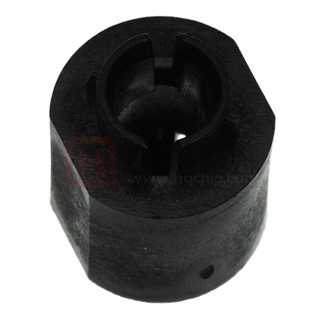
�multimec®
Low cap, excellent for foil overlay
5G + 1JS
■■ Round cap
■■ Ø9.6 mm
■■ h =10.4 mm
■■ Material: ABS/polycarbonate
RR2
■■ Temp. Range:
2
•• Solid cap: -40/+65°C
•• Transparent cap: -40/+85°C
0,3 Min.
0,3
0,8
0,8
Min.1JS-Ø10.4
10,16
10,16
■■ Panel cut-out:
Max. 12,5
12,5
Max.
2,4
10,4
0,7
5GT ++ 1JS
1JS
5GT
4:1
4:1
7,62
7,62
*Legends on the picture
are custom
10
10
DIMENSIONS
5GT + 1JS
4:1
SMD w/LED + 1JS
0,8
14,0
14,0
7,62
7,62
7,62
Max 10,3
10,3
Max
10
12,50
12,50
1,20
9,6
7,62
9,66
9,
0,8
10
2,4
0,7
10,4
0,7
0,3 Min. 10,16
Max. 12,5
5GSxx ++ 1JS
1JS
5GSxx
4:1
4:1
RR2
2
2,4
R
2
10,4
TH + 1JS
Tolerances -/+0.2mm
10
All dimensions in mm
9,6
9,6
2,50
2,50
5GSxx + 1JS
4:1
2,4
10,4
0,7
R
2
14,0
7,62
ILLUMINATED
– HOW TO ORDER
Switch
Max 10,3
Actuation force
LED
Cap transparent
12,50
+
TH9 through-hole
SH9 surface mount
20
35
65
Q*
1,20
7,62
9,6
0,8
5 G
Mounting
2,50
1 J S
02 blue
22 green
42 yellow
61 white
82 red
2242 green/yellow
8222 red/green
8242 red/yellow
11 transparent
16 frosted white
NON-ILLUMINATED– HOW TO ORDER
Switch
Mounting
Actuation force
+
5 G
TH9 through-hole
SH9 surface mount
12
Cap solid colour
20
20Q
35
65
Colour code
Colour code
1 J S
00 blue
02 green
03 grey
04 yellow
06 white
08 red
09 black
Ordering example:
5GTH935+1JS08 without illumination OR 5GTH93501+1JS16 with illumination OR *5GTH92001Q (illuminated quiet version)
Please see colour codes, updates of products and changes of specifications on www.apem.com
�19,1
11,6
0,3
11,6
0,3
7,62
0,8
Min. 10,16
Max. 12,5
7,62
14,3
14,3
■■ Square caps
■■ Different top surfaces: flat, convex or concave
■■ 14.3 mm x 14.3 mm
■■ h =19.1 mm; 20.2 mm; 20.1 mm
14,3
■■ Material:
ABS/polycarbonate
■■ Temp. Range:
•• Solid cap: -40/+65°C
•• Transparent5GT+1KS
cap: -40/+85°C
■■ Panel cut-out: 1KS/1KBS/1KCS-14.7 x 14.7
All dimensions
in mm
5GTxx+1KBS
5GSxx+1KS
5GTxx+1KBS
5GTxx+1KBS
14,3
5GTxx+1KBS
5GTxx+1KBS
Tolerances -/+0.2mm
Custom5GSxx+1KCS
solution
5GSxx+1KCS
5GSxx+1KCS
5GTxx+1KBS
5GSxx+1KCS
5GSxx+1KCS
1KS
DIMENSIONS
Bezel
19,1
R18,7
5
RR
11
88,7,755
R25
R25
R25
R25R25
2,1
19,1
19,1
20,2
14,3
14,3
02 blue
1KS
1KS
22 green
Bezel
Bezel
Bezel
42 yellow
61 white
82 red
2242 green/yellow
8222 red/green
16,4
16,4
1KBS
1KBS
824216,4
red/yellow
19,1
0,3
0,3
14,3
2,1
2,1
20,1
19,1
11,6
14,6
17,75
17,75
17,75
11,6
0,8
Min. 10,16
Max. 12,5
7,62
14,3
1 6
14,6
17,75
17,75
14,6
14,6
14,3
Frosted white lens
1KS
19,1
0,3
14,3
1 K S
1KCS
1KCS
5GT+1KS
17,75
1KCS
17,75
17,75
14,6
14,6
14,6
+
7,62
14,6
+
14,3
17,75
Bezel
2 K
1KCS
17,75
Colour17,75
code
00 blue
02 green
03 grey
04 yellow
06 white
08 red
09 black
03 grey
06 white
08 red
09 black
17,75
1KS
Bezel
2,1
20
20Q
35
65
Cap
0,8
14,0
14,6
14,6
14,6
7,62
17,75
0,8
Min. 10,16
Max. 12,5
1KCS
17,75
14,3
14,3
5 G
TH9 through-hole
SH9 surface mount
16,4
17,75
0,3
14,3
Actuation force
1KCS
1KCS
1KCS
19,1
20,2
11,6
2,1
2,1
20,2
16,4
16,4
1KBS
11,6
19,1
1KBS
1KBS
1KBS
14,6
7,62
14,6
14,614,6
14,3
14,3
R25
16,4
16,4
14,3
Mounting
17,75
Bezel
0,3
14,3
14,0
14,3
0,8
NON-ILLUMINATED– HOW TO ORDER
Switch
11,6
14,3
14,3
11,6
5
R18,7
7,62
7,62
11,6
19,1
0,8
0,8
1KCS
5GSxx+1KCS
Bezel
1KCS
14,6
14,6
0,3
*For an illuminated quiet 2.0N switch
add Q
1KBS
1KBS
to the end of the switch part 1KBS
number.
Min. 10,16
Max. 12,5
Min. 10,16
Max. 12,5
2,1
0,3
2,1
2,1
7,62
Bezel
16,4
11,6
19,1
11,6
0,3
Min. 10,16
7,62
7,62
Max. 12,5
03 grey
06 white
08 red
09 black
1KBS
1KS
1KS
14,3
14,3
1KS
14,3
5GTxx+1KBS
Bezel
2 K
14,3
Frosted white lens
and
Bezel
Bezel
transparent
lid
5GT+1KS
0,8
14,3
7,62
1KS
19,1
19,1
11,6
11,6
0,80,8 0,3
+
1 1 1 6
0,8
Min. 10,16
Max. 12,5
5GT+1KS
5GSxx+1KS
20,2
19,1
11,6
0,3
7,62
Bezel
14,3
14,3
+
14,3
14,3
0,8
14,0
1KS
7,62
2,1
20
35
65
Q*
5 G
0,8
14,0
7,62
0,8
17,75
TH9 through-hole1KS
1KS1KS
SH9 surface mount
11,6
Cap
0,8
Min. 10,16
Max. 12,5
Min. 10,16
Max. 12,5
14,3
LED
0,3
0,3
7,62
19,1
Actuation force
5GT+1KS
14,3
R25
R25
19,1
11,6
5GT+1KS
Mounting
5GSxx+1KCS
14,6
5
R18,7
5
0,3
0,8
14,0
7,62
5GSxx+1
17,75
14,3
14,3
14,3
19,1
19,1
0,8
14,0
17,75
11,6
5GTxx+1KBS
14,3
14,3
14,314,3
14,3
Switch
0,3
ILLUMINATED – HOW TO ORDER
7,62
5GTxx+1KBS
14,3
11,6
11,6
5
0,8
1KCS
R18,7
14,3
14,3
14,3
14,314,3
14,0
7,62
7,62
14,3
14,3
14,3
14,3
14,3
14,3
14,3
14,3
14,3
14,3
14,3
14,3
5GSxx+1KS
5GSxx+1KS
0,80,8
R18,7
14,6
11,6
0,3
7,62
Min. 10,16
Max. 12,5
14,3
0,3
14,6
14,0
14,0
7,62
7,627,62
19,1
0,3
0,8
14,0
20,1
20,1
20,2
0,8
0,8 0,8
7,62
16,4
5GTxx+1KBS
19,1
0,8
14,0
14,014,0
7,62
7,62Min. 10,16
Max. 12,5
0,3
0,3 11,6
11,6
11,6
20,1
0,3
0,3
0,3
0,80,8 0,3
11,6
1KBS
5GSxx+1KS
14,3
7,62
7,627,62
19,1
19,1
11,6
11,6
0,30,3
Min.
Min.
10,16
10,16
Max.
Max.
12,5
12,5
7,62
0,8
0,8 0,8
19,1
20,2
20,2
19,1
19,1
19,1
20,2
20,2
11,6
11,6
20,2
11,6
19,1
19,1
19,1
0,8
7,62
7,62 0,3
14,0
0,3 0,3
Min. 10,16
Min.Min.
10,16
10,16
Max. 12,5
Max.
Max.
12,512,5
14,3
R25
7,62
0,3
11,6
11,6
19,1
Min. 10,16
Max. 12,5
0,80,8
185,75
R18R,7
Bezel (optional)
0,8
11,6
0,3
SMD w/LED + 1KCS
R18,7
5
TH w/LED + 1KBS
11,6
SMD w/LED + 1KS
17,75
1KS
x+1KS
16,4
1KBS
14,3
17,75
14,6
14,6
14,3
KS
+1KS
14,0
5G + 1KS/1KBS/1KCS+2K
2,1
0,3
Square cap with different top surface options
0,8
20,2
R
19,1
multimec®
1KCS
17,75
Ordering example:
5GTH93501+1KCS1116+2K09 with illumination OR 5GSH965+1KS0916+2K03 without illumination OR *5GTH92082Q (illuminated quiet version)
Please see colour codes, updates of products and changes of specifications on www.apem.com
13
�multimec®
5G + 1NS
Teardrop-shaped cap
■■ Teardrop-shaped cap
■■ Ø9.6 mm; ☐ = 4.9 mm
■■ h =14.9 mm
■■ Material: ABS/polycarbonate
■■ Temp. Range:
•• Solid cap: -40/+65°C
•• Transparent cap: -40/+85°C
■■ Panel cut-out: 1NS-Ø10.2/ ☐ = 5.1
All dimensions in mm
Tolerances -/+0.2mm
DIMENSIONS
9,4
7,4
4,9
SMD + 1NS
4,9+ 1NS
TH w/LED
14
0,8
0,8
13,3
14,9
8,2
14,9
7,62
0,8
7,62
13,3
11,8
11,8
9,6
R5,
5
11,0
R5,
5
9,6
13,3
11,0
9,6 9,6
Min 10,16
Max 12,5
Min 10,16
Max 12,5
11,8
13,3
11,0 11,0
7,5
7,5
0,8
0,8
0,3
7,62
7,62
14
0,8
0,3
8,2
7,62
7,62
18,514,9 18,5
14,9
7,5 7,5
0,8
0,8
8,2 8,2
14
4,9
7,5
0,8 0,8
7,511,0
3,5
0,33,5
0,3 0,3
0,3
14
7,4
11,0
9,4
4,9
11,8
ILLUMINATED – HOW TO ORDER
Switch
Mounting
Actuation force
LED
Cap transparent
+
5 G
TH9 through-hole
SH9 surface mount
20
35
65
Q*
1 N S
02 blue
22 green
42 yellow
61 white
82 red
2242 green/yellow
8222 red/green
8242 red/yellow
16 frosted white
*For an illuminated quiet 2.0N switch add Q
to the end of the switch part number.
NON-ILLUMINATED– HOW TO ORDER
Switch
Mounting
Actuation force
+
5 G
TH9 through-hole
SH9 surface mount
14
Cap
20
20Q
35
65
Colour code
Colour code
1 N S
03 grey
09 black
Ordering example:
5GSH965+1NS09 non-illuminated OR 5GTH93502+1NS16 with illumination OR *5GTH92082Q (illuminated quiet version)
Please see colour codes, updates of products and changes of specifications on www.apem.com
�multimec®
Concave rectangular caps
5E/5G + 1PS/1QS/1RS
■■ Rectangular caps
■■ Concave top surface
■■ 12.5 mm x 6.5 mm
■■ h =15.7 mm
■■ Material: ABS/polycarbonate
■■ Temp. Range:
•• Solid cap: -40/+65°C
•• Transparent cap: -40/+85°C
1RS
■■ Panel cut-out: 1PS/1QS/1RS-7.0 x 13.0, R max. 1.0
1QS
Tolerances -/+0.2mm
6,5
Max 12,5
10.16
10.0
Cap
5 G
+
+3
Ø=0.9
4
ø 6.5
Min 10.16
Max 12.5
15,7
10,4
10.4
15.7
10.3
10,3
3
3
7,62
7.62
10.0
10.0
10.0
12.5
10,16
1
-2
4
+3
+3
Ø0,9
Ø=0.9
ø 6.5
Min 10.16
Max 12.5
7.62
11 transparent
16 frosted white
0.3
0.8
7.62
10.16
Cap
10.0
-2
1
4
+3
12.5
10,16
1
-2
Colour code
4
Ø=0.9
7.62
10.0
Actuation force
20
20Q
35
65
7.62
2.5
0.8
10.0
+
TH9 through-hole
SH9 surface mount
1 transparent
6 frosted white
0.8
10.0
NON-ILLUMINATED– HOW TO ORDER
5 E
2.5
1
4
Max 12.5
ø 6.5
1PS
0.3
0.3
7,62
3+
10.16
-2
10.0
4
Ø0,9
7.62
10.0
7.62
1
Min 10.16
Max 12.5
1RS
10.4
15.7
-2
7,62
*For an illuminated quiet 2.0N switch add Q
to the end of the switch part number.
5 G
7,62
3+
Ø0,9
00 blue
03 grey
09 black
0.8
0.3
+3
10.0
4
10,16
Mounting
Min 10.16
Max 12.5
Ø0,9
Max 12.5
Switch
1QS
1
10.4
15.7
-2
ø 6.5
7.62
02 blue
22 green
42 yellow
61 white
82 red
2242 green/yellow
8222 red/green
8242 red/yellow
Lens
2.5
Max 12.5
4
+3
12.5
Ø0,9
1
-2
10.4
15.7
20
35
65
Q*
+3
10,16
Colour code
Ø=0.9
TH9 through-hole
SH9 surface mount
1
4
10.0
+3
Ø0,912.5
10,16
-2
Max 12.5
10,16
4
10.3
10.0
4
1
-2
4,4
7.62
LED
1
7.62
10.0
1
7.62
10.0
Actuation force
10.0
Mounting
7.62
10.16
-2
ILLUMINATED – HOW TO ORDER
Switch
7.62
+3
Ø0,9
10.0
4,4
0.8
10,16
-2
1.2
4
10.3
0.3
7.62
1.2
3+
1RS
Min 10.16
Max 12.5
0.8
0.3
7,62
4
0.8
0.3
10.3
7,62
Min 10.16
Max 12.5
Ø0,9
7.62
Min 10.16
Max 12.5
1.2
10.3
1RS
2.5
1
ø 6.5
0.8
Min 10.16 0.3
Max 12.51
-2
3+
7,62
-2
Max 12.5
ø 6.5
10,16
Max 10,3
10.3
1.2
3
4
10,16
10.4
15.7
Max 12.5
3
Max 10,3
10.0
1
ø 6.5
7,62
-2
10.3
Ø0,9
10.4
15.7
7.62
Max 10,3
1QS
10.4
15.7
10,16
0.8
7.62
Max 12.5
ø 6.5
7,62
Max 10,3
1QS
10
10.4
15.7
Max 12.5
12.5
7,62
0,3
0,8
Min 10,16
Max 12,5 7,62
0.3
Min 10.16
Max 12.5
7.62
7.62
0,8
14
10.1
7.62
Min 10,16
Max 12,5
0.8
0.3
Min 10.16
Max 12.5
6.5
0,3
7,62
10.3
0.8
7,62
7,62
15.7
10.4
Min 10,16
Max 12,5
15,7
10,4
0.3
0,3
10.1
10
6,5
10,4
0,8
0,3
0,8
Min 10,16
Max 12,5
0,3
15,7
15,7
Max 12.5
6.5
10.4
15.7
Max 12.5
10.4
15.7
10,4
6.5
6,5
TH w/LED (5G) + 1QS
10.0
Max 12.5
10,4
TH w/LED (5G) + 1RS
15,7
SMD (5E) + 1PS
12,5
Max 12,5
6,5
10.0
Max 12,5
10,3
Max 12,5
DIMENSIONS
+3
Ø0,9
1.2
All dimensions in mm
1RS
2.5
1PS
00 blue
02 green
03 grey
04 yellow
06 white
08 red
09 black
Ordering example:
5GTH935+1PS08 without illumination OR 5GSH96542+1RS001 with illumination OR *5GSH92061Q (illuminated quiet version)
Please see colour codes, updates of products and changes of specifications on www.apem.com
15
�multimec®
Cap range with variable heights and illumination options
5E/5G + 1SS/1IS/1LS
■■ Round caps
■■ 9 standard options in overall height
■■ Ø6.5 mm
■■ h =8-22.5 mm; 10.4-22.5 mm; 12-22.5 mm
■■ Material: polyamide
■■ Temp. Range:
•• Solid cap: -40/+160°C (1SS); -40/+65°C (1LS)
•• Transparent cap: -40/+85°C
■■ Panel cut-out: 1SS/1LS/1IS-Ø7.0
1SS
1SS
1SS
1LS
1LS1LS
1IS
1IS1IS
All dimensions in mm
1SS1SS
DIMENSIONS 1SS
1LS1LS
1LS
TH w/LED (5G) + 1LS
Min 10,16
6,5
6,4
Max 10,3
14
7,62
Mounting
Actuation force
Max 10,3
LED
Cap
02 blue
6,5
22 green
42 yellow
61 white
82 red
14
2242 green/yellow
8222 red/green
10
8242 red/yellow
1IS fully
illuminated
00 blue
02 green
03 grey
04 yellow
06 white
08 red
09 black
11 transparent
16 frosted white
7,62
Actuation force
TH9 through-hole
SH9 surface mount
20
20Q
35
65
6,4
10,4 - 22,5
6,4
Min 10,16
Max 12,5
Max 10,3
Cap
12.0 19.0
15.0 22.5
16.0
Height 1IS
0,8
10.4 16.0
7,62
11.0 19.0
12.0 22.5
15.0
3
Colour code
+
5 E
1 transparent
6,5
2 green
4 yellow
6 frosted white
80,3red
0,8
NON-ILLUMINATED– HOW TO ORDER
Mounting
1LS with lens
10
*For an illuminated quiet 2.0N switch add Q
to the end of the switch part number.
10,4 - 22,5 10,4 - 22,5
10,4 - 22,5 10,4 - 22,5
10,4 - 22,5 10,4 - 22,5
6,4
6,4
6,4
Height 1LS
.
8,0 - 22,5
20
35
65
Q*
0,3
TH9 through-hole
SH9 surface mount
16
Lens
+
3
5 G
Colour code
Max 10,3
5 G
Switch
1LS
7,62
Height
.
1SS solid colour 00 blue
02 green
03 grey
04 yellow
06 white
08 red
09 black
08.0 16.0
09.5 19.0
10.4 22.5
11.0
12.0
15.0
Ordering example:
5ETH920+1SS04-09.5 without illumination OR 5GSH93542+1IS16-19.0 with illumination OR *5GTH9208222Q (illuminated quiet version)
Please see colour codes, updates of products and changes of specifications on www.apem.com
12,0 - 22,5
Min 10,16
Max 12,5
3
0,8
Switch
0,8
ILLUMINATED – HOW TO ORDER
Max 10,3
0,8
0,3
1SS
0,8
7,62
14
7,62
10,4 - 22,5
12,0 - 22,5
10
8,0 - 22,5
0,3
MaxMax
10,310,3
Max 10,3
0,8
0,3
7,627,62
7,62
6,5
Max 12,5
10
Max
10,3
10,3
Max
10,3
Max
14 14
14
0,3
0,8
3 3
3
7,62
7,62
7,62
7,62
1414 14
0,8
0,8
8,0 - 22,5
14
1IS
7,62
7,62
7,62
6,5
3 3
MaxMax
10,310,3
3
Max 10,3
0,8
10
0,8
0,3
0,8
0,8 0,8
0,8
0,3 0,3
10,3
10,3
0,3 Max
Max
10,3
Max
Min Min
10,16
10,16
MinMax
10,16
12,512,5
Max
Max 12,5
6,5
6,5
7,62
7,62
7,62
0,3
0,3
0,3
7,627,62
1LS
7,62
Min
10,16
Min
10,16
Min
10,16
Max
12,5
Max
12,5
Max
12,5
0,3
1010 10
14 14
14
0,80,80,8
0,30,30,3
0,3
0,3
7,62
7,62
7,62
1IS
6,56,5
6,5
12,0 - 22,5
1414 14
1LS
6,56,5
6,5
0,8
0,8
0,8
0,3
0,3
0,3
0,3
0,3
0,3
6,5
6,5
6,5
6,5
12,0 - 22,5 12,0 - 22,5
12,0 - 22,5 12,0 - 22,5
12,0 - 22,5 12,0 - 22,5
1SS
8,0 - 22,5
8,0 - 22,5
8,0 - 22,5 8,0 - 22,5
8,0 - 22,5 8,0 - 22,5
6,5
6,5
6,5
6,56,5
10
10
10
SMD w/LED (5G) + 1IS
6,4
6,4
6,5
6,5
6,5
10
10
1IS 1IS
1IS
0,8
0,8
0,8
SMD (5E) + 1SS
10 10
10
Tolerances -/+0.2mm
�multimec®
Panel sealed cap solutions
5G + 1TS/1US/1VS + 1TW/1UW/1VW
■■ Square, round and half-ellipse
shaped caps
■■ Rounded top surface
■■ Option to have it panel sealed
•• IP65 = 5G+1TS+1TW
•• IP67 = 5G+1US+1UW
•• IP65 = 5G+1VS+1VW
■■ 10.6 mm x 10.6 mm; Ø10.6 mm;
10.6 mm x 13.25 mm
Tolerances -/+0.2mm
4
4 4
4
14,9
14,9
14,9
8,2 14,9
11
7,62
7,62
7,62
7,62
7,62
7,62
7,62
11
Distance between PCB
and front panel
4
11
10,8 0,1
14,9
6,7
0,8
0,3
0,1
10,8
0,1
10,8
7,62
1,2
10,4
14,9
8,2
7,62
7,62
1,2
10,4
11,8
6,7
0,3
1,2
7,62
0,8
14,9
8,2
8,2
8,2
14,9
14,9
6,7
3
4
11
4
11
11
11
11
11
4
4
4
4
4
1UW
1VS
1US
Dimensions (w/LED)
Dimensions (SMD)
1TS
-2
Ø10,6
14
11,8
+3
Ø 0,9
1US
14,9
0,8
8,2
7,62
+
1,2
10,4
14,65
6,7
17,5
3
2,5
1TW
12,5
2
1
4
1
10,8 0,1
0,3
7,62
Sealing
0,1
10,8 0,1
14,9
14,9
13,25
Ø 0,9
00 blue
03 grey
08 red
09 black
11,8
8,2
+3
0,8
4
13,25
14,65
12,0
4
2
1
12,0
1VS
1
7,62
4
Ø10,6
3
-2
22,0
7,62
12,5
Colour21,0
code
21,0
0,8
17,5
1VW
7,62
2,5
14
1,2
4
13,25
7,62
14,65
7,62
0,8
1
8,2
7,62
0,8
3
4
21,0
7,62
10,16
2
1,2
6,7
12,5
1
1VS
0,8
Dimensions (SMD)
7,62
10,16
2
8,2
8,2
Min. 10,16
7,62
Max 12,5
5,3
6,7
6,7
0,8
0,3
0,8
7,62
0,3
14
Cap
0,3
14,9
6,7
8,2
0,3
0,8
10,4
10,6
+3 10,6
Min.12,0
10,16
Max 12,5
11
11
0,8
14,9
8,2
0,3
8,2
7,62
0,8
1US
Dimensions (w/LED)
12,0
11,8
0,8
1
7,62
12,0
3
1VW
5,3
6,7
Min. 10,16
Max 12,5
Ø 0,9
11
11
11
11
4
10,6
12,0
1
1TW
2,5
Dimensions (SMD)
10,16
4
+
1
5,3
10,16
2
17,5
3
2,5
16 frosted white
2
10,4
12,0
14,65
4
12,5
1VS
1TS
8,2
4
7,62
12,0
4
Dimensions (through-hole)
14,9
0,8
8,2
+
0,8
Ø10,6
7,62
Min. 10,16
Max 12,5
14,9
7,62
6,7
0,3
10,6
20
20Q
35
65
3
-2
13,25
Ø 0,9
1US
10,16
0,8
7,62
12,0
10,6
10,6
12,0
1
1
14,65
0,3
7,62
Sealing
2
+3
0,8
22,0
7,62
12,5
1
13,25
Ø 0,9
0,8
0,3
Min. 10,16
Max 12,5
4
22,0
22,0 22,0
+3
4
-2
21,0
0,8
17,5
14
Colour21,0
code
1VS
1
12,0
6,7
0,8
8,2
10,16
2
4
6,7
6,7
10,4
7,62
10,6
14,9
6,7
Dimensions (through-hole)
7,62
Actuation force
4
TH9 through-hole
SH9 surface mount
1TS
0,8
3
Ø10,6
14
Ø10,6
1US
0,8
0,3
2,5
1TS
Dimensions (w/LED)
Min. 10,16
Max 12,5
1
4
13,25
7,62
14,65
1VS
Dimensions (SMD)
10,16
2
3
-2
3
NON-ILLUMINATED– HOW TO ORDER
1
4
10,16
1
4
10,6
12,0
1TS
5 G
10,6
02 blue
17,5
17,5 17,5
22green
42 yellow
61 white
82 red
2242 green/yellow
8222 red/green
8242 red/yellow
21,0
7,62
12,5
11,8
12,0
0,8
1VS
0,8
Dimensions (SMD)
Min. 10,16
7,62
Max 12,5
5,3
Cap
0,3
5,3
0,3
0,8
7,62
2
12,0
11,8
0,8
Ø 0,9
2
Dimensions (through-hole)
Mounting
+
+3 10,6
Min.12,0
10,16
Max 12,5
4
14
10,16
10,16
*For an illuminated quiet 2.0N switch add Q
to the end of the switch part number.
Switch
1
1US
Dimensions (w/LED)
14,9
-2
0,8
Dimensions (w/LED)
14,9
0,8
Ø10,6
7,62
Min. 10,16
Max 12,5
20
35
65
Q*
0,8
8,2
0,3
14,9
7,62
10,16
8,2
3
10,6
12,0
TH9 through-hole
21,0
21,0 21,0
SH9 surface mount
LED
0,8
1
4
12,0
5 G
7,62
12,0
2
6,7
Actuation force
Min. 10,16
Max 12,5
7,62
0,8
8,2
Mounting
7,62
Min. 10,16
Max 12,5
1US
0,3
0,8
0,3
Dimensions (through-hole)
10,16
10,6
Switch
1TS
0,8
7,62
14,9
6,7
6,7
5,3
0,8
14,9
6,7
0,8
0,3
Min. 10,16
Max 12,5
1VS
Dimensions (SMD)
Dimensions (through-hole)
11
11
11
11
1TS
1US
Dimensions (w/LED)
ILLUMINATED – HOW TO ORDER
4
4
4
4
4
1TS
Dimensions (through-hole)
4
7,62
1,2
3
2,5
2,5 4 44 4
2,5 2,5
2,52,5
13,65
3
*mathematical
shape of half3
3
4ellipse
3 3
3 3
2,5
1,2
4
14,9
8,2
8,2
8,2 14,9
8,2
14,9
8,2
8,2
14,9
8,2
10,60,3
0,3
0,3
0,3
1,2
4
5,5
1
4
14,65
11
6,7 1111
6,7
6,7
6,7
6,7
6,7
0,3
0,8
0,3
0,3
6,7
6,7
10,4
13,25
22,0
22,022,0
4
13,25
2,5
13,25
13,25
14,65
13,25
13,25
13,25
13,25
14,65
14,65
14,65 14,65
14,65
14,65
13,25
+3
Ø 0,9 Ø 0,9
Ø 0,9Ø
Ø 0,9
0,9
2
5,3
1
2
1
+3
+3 Ø 0,9
4
Ø 0,9 4 +3 +3
+3 +3
4 4
4
12,5
12,5
1
12,5 12,5
12,512,5
12,5
1
2
2 2
2 2
1 1
1 1
12,5
11,8
10,4
11,8
7,62
7,62
4
Ø 0,9
7,62
0,8
0,8
0,80,8 0,8
7,62
7,62 7,62
7,627,62
7,62
4
12,0
14
4
4 +3
4
Ø10,6
Ø10,6
Ø
12,0
Ø10,6Ø10,6
Ø10,6
Ø10,6
10,6
12,0
12,0
12,0 12,0
12,0
12,0
3
Ø10,6
0,8
7,62
1,2
1,2
1,2
3
3 3
0,8
0,8
2
17,5
17,517,5
1V Cap
1TS
- 11x11 mm
1US - Ø11 mm
1VS Center of switch
4
4 3
14 14
14 14
10,4
11,8
11,8
10,4
10,4
11,8
11,8
11,8
10,4
10,4
10,4
11,8
3
7,62
7,62
4
4 4
5,3
1,2
4
21,0
21,021,0
3
7,62
43
1
14
14
Recommended
10,16
-210,16
1
10,16
10,16
10,16
-2 1
1 10,16 10,16
-2 1 1
-2 -2
-2 -2
1 1
7,62
7,62
7,62
4
10,6
10,612,0
10,6
10,6 10,6
12,0 10,610,6
12,0 12,0
12,012,0
12,0
4
10,16
-2
7,62
10,16
210,16
1
10,16
10,16 10,16
10,16
110,16
2 1 1
2 2
2 2
1 1
7,62
7,62
7,62
2 1
10,6
7,62
12,0
10,6
10,6 12,0
12,0
10,6
10,6
10,6
12,0
12,0
7,62
12,0
10,6 7,62
7,62
12,0
12,0
10,6
10,16
2
0,8
0,8
0,8
0,8
14,9
0,8
0,3
0,8
0,8
0,3
0,3 0,8
0,3
0,8
0,8
0,30,8
Min.10,16
7,62
7,62
Min. 10,16
21,0 0,3 0,3
0,8
0,3 0,3 0,8 0,8
0,3
0,3
0,80,8 0,8
0,8 0,8
22,0 14
0,30,3 0,30,8
0,3 7,62
7,62
Min.Max
10,16
Min. 10,1617,5
7,62
7,620,8
12,5
Min.
10,16
Max
12,5
10,16
Min. 10,16
Min.
10,16
10,16
Min.Min.
Min.
10,16
10,16
7,62 7,62Max 12,5
7,62 7,62
7,627,62
7,62
7,62
7,627,62
Min.
10,16
Min. 10,16
Max 12,5
Min.
10,16
Min.Min.
10,16
Max 12,5
Max
12,5
Max 12,5
Max
12,5
12,5
MaxMax
12,5
12,5
Max
12,5
Max 12,5
Max
12,5
MaxMax
12,5
0,3
5,3 5,3
5,35,3
0,8
8,2
5,3
0,8 14,9
8,214,9
8,2
11
8,2
14,9
14,9
8,2 14,9
8,2
14,9 1111
4
14,9
6,7
8,2
8,2
6,7
6,7
6,7
6,7
6,7
6,7
0,8
0,8
0,8
0,8
14,9 0,8
6,7
0,8
8,2
8,2
8,2
14,9
0,8
14,9
8,214,9
8,2
8,2
1111
14,9
14,9
8,2 14,90,8 11
4
4 4
8,2
14,9
6,7
6,7
6,7
6,7
6,7
6,7
0,8
6,7
6,7
0,8
0,8
0,8
SMD + 1VS+1VW
5,3
5,3
0,3
TH w/LED + 1US+1UW
Dimensions
(through-hole)
Dimensions
Dimensions
(through-hole)
(through-hole)
Dimensions
Dimensions
(through-hole)
(through-hole)
4 4
TH + 1TS+1TW
0,8
1VS
1VS
Dimensions (SMD)1VS
1VS
Dimensions (SMD) Dimensions (SMD)1VS 1VS1VS
Dimensions
(SMD)
Dimensions
Dimensions
(SMD) (SMD)
Dimensions
Dimensions
(SMD)(SMD)
1US
1US
Dimensions
(w/LED)
1US
1US
Dimensions (w/LED)Dimensions (w/LED)
1US 1US1US
Dimensions
(w/LED)
Dimensions
Dimensions
(w/LED) (w/LED)
Dimensions
Dimensions
(w/LED)
(w/LED)
1TS
PANEL CUT-OUT
1VS
1US
1TS
1TS
1TS
Dimensions (through-hole)
1TS
1TS 1TS1TS
sions (through-hole)
Dimensions (through-hole)
1,2
DIMENSIONS
11
11
11
4
All dimensions in mm
■■ h =14.9 mm
■■ Material: ABS/polycarbonate
(cap); silicone rubber (sealing)
■■ Temp. Range:
•• Solid cap: -40/+65°C
•• Transparent cap: -40/+85°C
•• Panel cut-out: 1TS-11.0 x 11.0,
1US-Ø11.0, 1VS-11.0 x 13.65
3
2,5
1UW
Ordering example:
5GSH935 + 1TS03 + 1TW without illumination OR 5GTH96542 + 1US16 + 1UW with illumination OR *5GTH92082Q (illuminated quiet version)
Please see colour codes, updates of products and changes of specifications on www.apem.com
17
�multimec®
Ellipse-shaped caps
5G + 1WAS/1WDS/1WPS
WAS
WAS
WAS
■■ Ellipse-shaped
caps
6,5
12,5
6,5
12,5
12,5
■■ Convex or concave top surface
■■ 6.5 mm x 12.5 mm; 8.0 mm x 15.2 mm
■■ h =15.7 mm
■■ Material: ABS/polycarbonate
14
7,62
14
7,62
7,62
■■ Temp. Range:
•• Solid cap: -40/+65°C
10
•• Transparent
cap: -40/+85°C
10
■■ Panel cut-out: 1WAS/1WPS-12.9x6.9, 1WDS-15.6x8.4
0,8
0,8
10,4
10,4
14,9
14,9
14,9
Min 10,16
Max 12,5
Max 10,3
Tolerances -/+0.2mm
TH + 1WDS
0,3
Min 10,16
0,8 0,8
0,8
Min 10,16
Max 12,5
Max 12,5
7,627,62
7,62
0,8
12,5
14,9
8,2
15,7
15,7
10,4
15
10,4
0,3
0,3
10,4
10,4
15,7
0,8
15,7
15,7
10,4
10,4
Max Max
Max
10,3
10,3
10,3
10
6,5
R60
14,91
0,3
10,4
10,4
14,89
14,9
14,9
15
0,8
10,4
14,91
10
Max 10,3
10,3
Max 10,3
Max
0,8
0,8
0,8
Min 10,16
Max 12,5
0,8
7,62
7,62 7,62
7,62
Max 10,3
10
10
10
0,8
10
10 10
10
*For an illuminated quiet 2.0N switch add Q
to the end of the switch part number.
WDS 8,0
10
10
10
0,8
14,9
8,2
12,5
7,62
R60
1WDS
16 frosted white
0,3
0,8
Min 10,16
Max 12,5
7,62
1WPS
15,7
1WAS
10
Colour code
0,8
10,4
0,8
0,8
0,8
0,8
14,9
14,9
8,2
8,2 14,9
10,4
+
6,5
Min 10,16
Max 12,5
7,62
Max 10,3
WDS
WPS + illu
WDS
15,3
0,8
10
10
10
7,62
10
10
14,89
14,91
15
10,4
14,91
10
10
8,2
8,2
8,2
0,3
0,3
0,8
12,5
Cap
0,3
12,5
02 blue
22 7,62
green
0,8 0,8
0,8
42 yellow
7,627,62
7,62
61 white
82 red
2242 green/yellow
8222 red/green
WAS
8242 red/yellow
WPS + illu
10
0,3
0,3
Min 10,16
10,16
Min 10,16Min
Max 12,5
12,5
Max 12,5 Max
20
35
14
0,8
0,8
0,3 0,3
0,3
65
7,62
7,62 14 7,62
Min 10,16
Min 10,16
10,16
Min
Q*Max Max
Max
12,51012,5
12,5
14,9
14,9
14,9
6,5
TH9 through-hole
SH9 surface mount
15,215,2
15,2
12,5
10,4
LED
8,2
6,5
14,9
5 G
10
15,2
15,2
Actuation
8,0 8,0
8,0 force
15,2
0,8
Mounting
WPS + illu
WAS
0,8
0,8
8,0
8,0
15,2
8,0
WDSWDS
WDS
0,8
Switch
8,0
WDS
15
WDS
WDS
ILLUMINATEDWAS
– HOW TO ORDER
10
7,62
WAS
WDS
0,3
12,512,5
12,5
12,5
0,3
0,3 0,3
0,3
Min 10,16
Min 10,16
10,16 7,62
Min
7,62 Min 10,16
7,62
Max 12,5
Max Max
Max
12,512,5
12,5
7,62
0,8
0,8
0,8
15,2
15,2
15,2
7,62
10
10
10
10 10
10
8,0
6,5 6,5
6,5
0,8
0,8
0,8
0,8
10,4
10,4
10,4
14,9
14,89
14,89
14,89
12,5
14
0,3
0,3
Min 10,16
10,16
Min 10,1614
Min
Max 12,5
12,5
Max 12,5 Max
0,3
7,627,62
7,62
0,3
0,3
0,3
14
14 14
8,0
8,0
R60 R60
R60
6,5
14,9
14,9
14,9
10,4
10,4
0,8
10,4
0,3
7,62
7,62
12,5
R6012,5
R60
R60
6,5
12,5
12,5
14,9
15,7
6,5
12,512,5
12,5
0,8
0,8
6,5 6,5
6,5
6,5
6,5
15,2
0,3
Max 12,5
+
5 G
20
20Q
35
65
0,8
1WAS
1WPS
1WDS
WDS
00 blue
03 grey
08 red
09 black
30 ultra blue
40 dusty blue
42 aqua blue
53 metal
15,3 light grey
57 metal dark grey
8,2
15
0,8
WDS 8,0
7,62
7,62
Min 10,16
Max 12,5
10
7,62
0,8
Colour code
0,8
10
TH9 through-hole
SH9 surface mount
Cap
0,8
Actuation forceMin 10,16
8,2
15,3
15
Mounting
14,9
WPS + illu
0,3
8,2
Switch
8,2
NON-ILLUMINATED– HOW TO ORDER
WAS
15
0,8
8,0
15
0,8
Ordering example:
0,3
15,3
0,8
5GTH935+1WAS00 without illumination
OR 5GSH96582+1WDS16 with illumination OR *5GSH92042Q (illuminated quiet
version)
7,62
Min 10,16
12,5
Please see colour codes, updates ofMax
products
and changes of specifications on www.apem.com
8,2
18
0,8
0,8
WPS + illu
WAS
14,9
14,9
TH w/LED + 1WPS
WDS
WDS
WDS
WPSWPS
WPS
+ illu+
+ illu
illu
15,7
WPS ++ illu
illu
WPS + illuWPS
10,48,2
8,2
10
All dimensions in mm
DIMENSIONS
12,5
12,5
0,3
0,3
0,3
10
10
10
WASWAS
WAS
6,5
0,3
0,3
0,3
14
SMD + 1WAS
10,4
14,89
14,89
14,89
0,8
6,5
�multimec®
Rectangular cap with soft edges
■■ Rectangular cap
■■ 7.4 mm x 9.4 mm
■■ h =18.5 mm
■■ Material: ABS/polycarbonate
■■ Temp. Range:
•• Solid cap: -40/+65°C
•• Transparent cap: -40/+85°C
■■ Panel cut-out: 1XS-9.8 x 7.9
5G + 1XS
9,4
7,4
Tolerances -/+0.2mm
0,3
DIMENSIONS
0,8
11,0
7,5
0,8
0
14
14
7,62
SMD w/LED + 1XS
9,4
7,4
9,4
4,9
7,4
9,4
7,4
4,9
7,4
13,3
4,9
7,62
0,8
0,8
14
14
7,62
7,62
0,8
0,8
0,8
18,5
11,0
14,9
9,6
8,2
14,9
18,5
7,5
8,2
0,3 7,5
0,3
0,3
11,0
11,0
7,5
0,8
3,5
0,8
3,5
18,5
14 14
R5,
5
0,3
7,62
7,62
13,3
13,3
11,8
11,8
13,3
Mounting
Actuation force
R5,
5
LED
Cap
+
5 G
TH9 through-hole
SH9 surface mount
20
35
65
Q*
9,6
10
R5,
5
11,0
9,6
11,0
9,6
ILLUMINATED
R5,5
R5,5 – HOW TO ORDER
9,6
11,8
10
Switch
0,3
Min 10,16
Max 12,5
7,62
11,0
10
0,8
0,8
11,0
Min 10,16
Max 12,5
R5,5
0,3
0,3
Min 10,16
Max 12,5
10
7,5
7,5
3,5
18,5
10
7,5
11,0
11,0
11,8
0,8
TH + 1XS
9,4
3,5
0,8
Min 10,16
Max 12,5
7,5
All dimensions in mm
0,3
0,3
7,5
3,5
18,5
11,0
4,9
9,4
Colour code
1 X S
02 blue
22 green
42 yellow
61 white
82 red
2242 green/yellow
8222 red/green
8242 red/yellow
11 transparent
16 frosted white
NON-ILLUMINATED– HOW TO ORDER
Switch
Mounting
Actuation force
Cap
+
5 G
TH9 through-hole
SH9 surface moun
20
20Q
35
65
Colour code
1 X S
00 blue
02 green
03 grey
04 yellow
06 white
08 red
09 black
Ordering example:
5GTH9352242+1XS16 with illumination OR 5GSH965+1XS02 non-illuminated OR *5GTH9208242Q (illuminated quiet version)
Please see colour codes, updates of products and changes of specifications on www.apem.com
19
�foilmec™
Square cap for foil overlay
5E + 1YS
■■ Square cap
■■ Designed for foil overlay
■■ 15 mm x 15 mm
■■ h =12.5 mm
■■ Material: ABS/polycarbonate
■■ Temp. Range: -40/+65°C
■■ Panel cut-out: 1YS-16 x 16
All dimensions in mm
13
,9
0
10
,
16
SMD
Tolerances -/+0.2mm
DIMENSIONS
RECOMMENDED PLACEMENT OF LEDS
2,54
1,6
1,6
12,50
,5
,5
R1
R1
R1,5
R1
6
,1
10
12,50
13,90
20
20Q
35
65
13
7,62
Cap
+
13,90
TH9 through-hole
SH9 surface mount
,0
1,6
0,3
Actuation force
2,50
1 Y S 0 6 1 6
1YS0616 white cap with frosted white lens
15
,0
15
,0
Mounting
7,62
5 E
0,8
14
7,62
1,20
Switch
1,6
12,5
12,5
,9
0
,5
,5
,5
,5
R1
R1
R1
R1,5
,5
RR11,5
HOW TO ORDER
3
R1
,5
H: The height recommendation does not include the foil. We recommend
embossing the foil to follow the curve of the keycap.
A=16
h 12,0
=11,8±0,1
0,1
H=
A: We recommend you to allocate enough space for travel of the foil and
leave the area free from adhesive. Switch travel = 1 mm.
The best tactile feeling is obtained with a small pretravel.
The dimension H is based on an embossed foil. With a flat foil the dimension ”H” will have to be adjusted, and enough area between the cap and
front panel needs to be addressed to ensure foil flexibility.
Ordering example: 5ESH935+1YS0616
Please see colour codes, updates of products and changes of specifications on www.apem.com
20
1,6
LED Recommendation
SMD: 1206 - 0805 - 0603 - 0402
TH: 3 mm - Ø max 3.2 - Height max 6.5 mm
Ø3mm
13,90
6
,1
10
0
,9
0
13
15
,0
7,62
,9
6
15
,0
7,62
15
,0
13,90
15
,0
1,20
15
,0
15
,0
15
,0
15
,0
2,50
15
,0
15
,0
15
,0
10,16
13,90
0,8
7,62
7,62
13
1,6
0,8
7,62
14
1,6
12,5
1,6
0,8
0,8
10
14
12,5
13,90
0,3
12,5
0,3
0,8
13,90
7,62
7,62
Ø3mm
PCB layout with LED
placement
13,90
1
7,62 5,0
14
TH
,1
14
2,54
2,54
,0
15
,0
15
,0
15
15
,0
0,8
10,16
14
PCB layout with LED
placement
15
,0
7,62
12,5
14
7,62
12,5
0,3
12,5
1,6
7,62
7,62
1,6
7,62
0,3
0,3
0,8
1,6
1,6
1,6
Min. 10,16
7,62
Max 12,5
0,3
0,3
7,62 Min. 10,16
7,62
Max 12,5
SMD
0,3
14
in. 10,16
ax 12,5
1,6
1,6
12,5
12,5
12,5
0,3
SMD
2,54
SMD + 1YS
12,5
TH + 1YS
�multimec®
Cap solution for navigating
■■ Round solution
■■ Designed for navigating a display or controlling a unit
■■ 90° R=17.5 mm; Ø14.3 mm (Ø34.25 mm)
■■ h =12.2 mm; 11.7 mm
■■ Material: ABS/polycarbonate
■■ Temp. Range:
•• Solid cap: -40/+65°C
•• Transparent cap: -40/+85°C
■■ Panel cut-out: 1ZB-R1 7,1 R2 17,5 – 17,75 90° 1ZCS-Ø14.7
■■ navimec™ panel cut-out: Ø35,0 - 35,5 Depending on application
25,00
2
DIMENSIONS
11,7
11,7
11,7
11,7
0,8
7,62
0,8
7,62
7,620,8
7,62 7,62 7,62
7,62
1
3
2
4
1
2
4
3
4
1
3
2
4
4
2
3
1
1,2
1
2
1,8
25,00
8
3
2
1
4
3
1
3
10,16
1
1
4
2
4
2
4
3
1
4
8
3
1
7,62
12,50
Legend
code
2
Ø14,3
2,5
DLMH136
7,62
12,50
8
0,3
1,2
LMH118 OK
LMH123
2,5
1 Z C S 1 6
11,7
1,8
Ø14,3
8
12,2
7,62
3
1,2
1 Z B 1 6
2
7,62
0,3
2
0,8
14
3
1,5
*For an illuminated quiet 2.0N switch add QMin 10,16
Max 12,5
to the end of the switch part number.
0,3
1,2
2
R1
R=17,5
(actuated)
4
1
Frosted
white with 0,8black hard
14
7,62
paint and laser marking
R=7,4
2
4
We recommend using through-hole terminals
for precise placing.
0,3
02 blue
(actuated)
Min 10,16
7,62
Max 12,5
22 green
42 yellow
90°
10,16
61 white
82 red
2242
green/yellow
R=7,4
8222 red/green
0,8
8242 red/yellow
4
3
4
8
1,21,2
1,2
7,62
7,62
8
12,2
TH9 through-hole
20
(SH9 surface mount) 35
65
Q*
2
3
1
3
1,5
+
R=17,50,8
0,3
3
4
7,62
Cap
1
1
3
0,8
90°
5 G
2,5
Min 10,16
Max 12,5
LED
2
7,62
Actuation force
1
TH
25,00
Mounting
2,5
3 3
3
2,5
2,5
2,5
0,3
Ø14,3
1
2
R1
Switch
7,62
Ø14,3
ILLUMINATED – HOW TO ORDER
3
25,00
11,7
Ø14,3
Ø14,3
2,5
2,5
1,2
Ø 0,9
ted)
44
1
1
7,62
Ø 0,9
44
12,2
Ø 0,9
ctuated) (actuated)
Ø14,3
Ø14,3 Ø14,3
3
3
22
1,2
3
Ø 0,9
2
12,50
12,50 1
1
1,8
3 4
44
12,50
2
7,62
7,62
7,62
7,62
7,62
7,62
7,62
12,50 12,50
12,50
1
4
1,5
4
4
2
R1
R=17,5
R=7,4
R=17,5
R=17,5
R=7,4 R=7,4
(actuated)
R=7,4
R=7,4
R=7,4
=17,5
R=17,5
(actuated)
(actuated)
R=7,4
5
12,50
10,16 10,16
10,16
10,16
10,16 10,16
10,16
1
22
2
1 1
2
7,62 7,62
7,62
90°
90° 90°
90°
2
4
25,00
14
14
7,62
90°
3
3
SMD
Max 12,5 Max 12,5
90°
4
25,00
25,00
14
1414
11,7
88
8 8
8
11,7
11,7
8
8
0,8
0,8
0,8
0,8
14
0,3
0,3
0,30,3
0,3
0,3 1,8
1,8
1,81,8
1,8
1,8
8
8
8
0,3
8
1,8
8
8 8
12,2
12,2
12,2
12,2
12,2 12,2
1,5
12,2
R1
,5
1,5
14
2
3
1
1,5
R1
1 5
R11,151,
R1 R
0,8
3
PCB layout for Navimec solution
R1
1,5
0,8
0,8
0,8
0,8
0,8
7,62 7,620,8
7,62
7,627,62 7,62
R1
SMD w/LED + 1ZCS
7,62
1
25,00
Tolerances -/+0.2mm
TH + 1ZB
1
4
11,7
All dimensions in mm
0,3
0,3
0,3
0,3
0,3
Min 10,16
0,16
Min 10,16Max
Min 10,16
Min 10,160,3
0,3
12,5
2,5
MaxMin
12,5
Max
12,5
10,16
10,16
MaxMin
12,5
0,8
14
7,62
90°
1,8
Actuation
force
R=17,5
14 R=7,4
+
R=17,5
(actuated)
R=7,4
3
11,7
1 Z B
4
Ø 0,9
Ø14,3
Colour code
1
2,5
1
4
2,5
3
Legend code**
pad printed
legends
Ø14,3
12,50
2
1,2
4
20
20Q
35
65
3
Ø 0,9
7,62
1
7,62
10,16
TH9 through-hole
2
(SH9 surface mount)
2
7,62
(actuated)
5 G
90°
4
Cap
0,8
0,3
0,8
7,62
8
8
12,2
Mounting
0,3
Min 10,16
Max 12,5
12,50
1
7,62
1,5
Switch
10,16
2
1,2
R1
NON-ILLUMINATED– HOW TO ORDER
7,62
°
navimec™ 5G + 1ZB/1ZCS
3
1 Z C S
03 grey
06 white
09 black
30 ultra blue
40 dusty blue
42 aqua blue
50 metal dark blue
53 metal light grey
57 metal dark grey
58 metal bordeaux
D136
120 MENU
038 RESET
121 FUNC
105 ENTER
122 HOME
118 OK
123
119 SET
** White legends on black caps are standard, other options are available but considered custom products. See pages 34-35 or www.apem.com
Ordering example: 4x 5GTH93561+1ZB16DLMH13609 + 1x 5GTH93561+1ZCS16LMH12309 (with illumination) OR 4x 5GSH920+1ZB09 + 1x
5GSH920+1ZCS09 (without illumination) OR *5GTH92002Q (lluminated quiet version)
Please see colour codes, updates of products and changes of specifications on www.apem.com
21
�multimec®
Module for navigating
navimec™ module
DIMENSIONS
Tolerances -/+0.2mm
5
5
All dimensions in mm
Ø30,3 0,1
■■ Module should be attached to the front plate with bolts (bolts not
supplied by MEC)
■■ Round solution
■■ Ø34.25 mm
■■ hmm
=11.7 mm; 12.2 mm
6,9 0,1
8-10
■■ Temp. Range:
PCB 1,5
PCB 1,5
•• Solid cap: -40/+65°C
2
•• Transparent cap: -40/+85°C
■■ Recommended panel cut-out: Ø35,0 - 35,5 Depending on application
Navimec Module
PCB 1,5
PCB 1,5
PCB 1,5
Ø3,2 (x4)
3,5
32
PCB 1,5 6,9 0,1
8-108-mm
10 mm
40
SW3
10
5
20
10
SW1
SW4
5
5
46,7
SW5
10
7,2
33
SW2
Ø34,25
10 10
10
When the 1ZB is activated the diameter changes from 34,25 mm to 35,0 mm
HOW TO ORDER
navimec™ Module ordering options:
■■ navimec™ Module excl. keycaps
■■ navimec™ Module incl. keycaps
■■ navimec™ Module incl. keycaps with legends
■■ Illuminated navimec™ Module excl. keycaps
■■ Illuminated navimec™ Module incl. keycaps with legends
Part no. for a module:
navimec™ Module has many customisation options regarding actuation
force, cap and LED colours and legends. Because of that “How to order”
has been placed on page 43.
See previous page for information on switch and cap options.
SEE THE “HOW TO ORDER” GRAPH AS WELL AS CIRCUIT DIAGRAM
AND CONNECTOR INFO ON PAGE 43
22
8-10 m
Ordering example:
95NA200913611806 (without illumination)
95NB350116LMH13612309 (with illumination)
Please see colour codes, updates of products and changes of specifications on www.apem.com
J1
J2
�multimec®
Panel sealed solution for a control unit
controlmec™ 5E/5G + 1ZW
6,9 0,1
2,0 0,2
■■ Round cap
■■ Panel sealed solution, designed to control a unit or
navigate a display
■■ Ø29.5 mm
■■ h =12.3 mm
1ZW
■■ Material: ABS/polycarbonate
■■ Temp. Range:
•• Solid cap: -40/+65°C
•• Transparent cap: -40/+85°C
■■ Panel cut-out: 1ZW-Ø30.3
All dimensions in mm
Tolerances -/+0.2mm
DIMENSIONS
1ZW
6,9 0,1
2,0 0,2
7,62
TH + 1ZW
MOUNTING EXAMPLE
10,16
Ø 0,9
Hole in front plate 30,3 ±0,1
1ZW
1ZZ Seal
12,3
5,2
29,5
1ZY Seal support
1ZW
PCB layout
1 pcs . 5GTH935 (+LED)
29,5
4 pcs. 5ETH935
12,3
5,2
10,16
7,62
PCB
7,62
25,0
10,16
Ø 0,9
25,0
10,16
Ø 0,9
We recommend using through-hole terminals for precise placing.
Cap
+
5 G
35
65
25,0
1Z
Mounting
TH9 through-hole
(SH9 surface mount)
35
65
25,0
136
118 OK
123
Seal support
Seal
+
00 blue
03 grey
06 white
08 red
09 black
16 frosted white
4 pcs. 5ETH935
25,0
Actuation force
5 E
1ZW
1 pcs. 5GTH935 (+LEDs)
Panel seal
1 Z Z
09 black
25,0
Switch
02 blue
22 green
42 yellow
61 white
82 red
2242 green/yellow
8222 red/green
8242 red/yellow
Legend code
Ø 0,9
25,0
TH9
1Z through-hole
(SH9 surface mount)
Colour code
5,1
LED (optional)
6,9 0,1
Actuation force
25,0
Mounting
2,0 0,2
Switch
7,62
ILLUMINATED – HOW TO ORDER
Hole in front plate Ø 30,3 ±0,1
1ZY
25,0
Ordering example:
5GTH935+1ZW09+4x 5ETH935+1ZZ09+1ZY without illumination OR 5GTH96582+1ZW16LMH13611809+4x 5ETH965+1ZZ09+1ZY with illumination
25,0
Please see colour codes, updates of products and changes of specifications on www.apem.com
23
�■■ Ø29.5
mm
pcs . 5GTH935
(+LED)
1 pcs .15GTH935
(+LED)
29,5
PCB PCB
■
■
h
=12.0
mm
pcs. 5ETH935
4 pcs.45ETH935
■■ Material: ABS/polycarbonate
■■ Temp. Range:
•• Solid cap: -40/+65°C
•• Transparent cap: -40/+85°C
■■ Panel cut-out: 1Z-Ø30.3
All dimensions in mm
29,529,5
6,9 0,1
5,1
PCB layout
10,16
7,62
1Z
1Z
1Z
front Ø
plate
30,3 ±0,1
Hole inHole
frontinplate
30,3ر0,1
25,0
25,0
25,0
1Z
25,0
pcs. 5GTH935
(+LEDs)
1Z
1 pcs.15GTH935
(+LEDs)
4
pcs.
5ETH935
4 pcs. 5ETH935
frontØplate
30,3 ±0,1
Hole inHole
frontinplate
30,3ر0,1
25,0
Ø 0,9
Ø 0,9
pcs. 5ETH935
4 pcs. 45ETH935
25,0
2,0 0,2 2
10,16
pcs. 5GTH935
(+LEDs)
1 pcs. 15GTH935
(+LEDs)
e Ø 30,3 ±0,1
29,5
29,5
Tolerances -/+0.2mm
5,1
5,1
5,1
Ø29,5
29,5
29,5
5,0
6,9 0,1 6,9 0,1
6,9 0,1
6,9 0,1
29,5
11,9
2,0 0,2
0,2 2,0 0,2
2,0
5,1
2,0 0,2
DIMENSIONS
1ZW
7,62
PCB PCB
12,3
5ETH935
5,2
5GTH935 (+LED)
29,529,5
control a unit or navigate in a display
25,0
We recommend using through-hole terminals
for precise placing. 25,0
25,0 25,0
ILLUMINATED – HOW TO ORDER
Switch
25,0 25,0
Mounting
Actuation force
LED (optional)
TH9 through-hole
(SH9 surface mount)
Switch
Cap
Colour code
Legend code
1Z
00 blue
03 grey
06 white
08 red
09 black
16 frosted white
136
+
5 G
35
65
Mounting
Actuation force
TH9 through-hole
(SH9 surface mount)
35
65
02 blue
22 green
42 yellow
61 white
82 red
2242 green/yellow
8222 red/green
8242 red/yellow
5 E
24
Ordering example:
5GTH935+1Z03 +4x 5ETH935 without illumination OR 5GTH96561+1Z16LMH13611809 +4x 5ETH965 with illumination
Please see colour codes, updates of products and changes of specifications on www.apem.com
12,3
pcsSeal
. 5GTH935
(+LED)cap
1 pcs 1ZY
.15GTH935
(+LED)
■■ Round
support
1ZY Seal
support
pcs. 5ETH935
■■ Designed to
4 pcs. 45ETH935
12,3
al support
5,2
1ZYsupport
Seal support
1ZY Seal
1ZZ Seal
1ZZ Seal
5,2
al
TH + 1Z
controlmec™ 5E/5G + 1Z
1ZZ Seal
1ZZ Seal
5,2
Cap for a control unit
2,0 0,2
front
plate
30,3 ±0,1
Hole inHole
frontinplate
30,3±0,1
5,2
ront plate 30,3 ±0,1
6,9 0,1
2,0 0,2
multimec®
2,
Hole
frontplate
30,3 ±0,1
1ZW
Hole in
frontinplate
30,3±0,1
1ZW
118 OK
123
�multimec®
Panel sealed or non-panel sealed module
controlmec™ module
■■ Module should be attached to the front plate with
bolts (bolts not supplied by MEC)
■■ Round cap
■■ Panel sealed or non-panel sealed solution
■■ Ø29.5 mm
■■ h =12.3 mm; 12.0 mm
■■ Temp. Range:
•• Solid cap: -40/+65°C
•• Transparent cap: -40/+85°C
■■ Panel cut-out: 1ZW/1Z module-Ø30.3
All dimensions in mm
Tolerances -/+0.2mm
DIMENSIONS
1Z module
1ZW module
Ø3,2 (x4)
Ø3,2 (x4)
PCB 1,5
PCB 1,5 PCB 1,5
3,5
PCB 1,5
20
3333
SW3
46,7
33
SW2 SW1 SW4
46,7 33
SW3
6,9 0,1
PCB
PCB1,5
1,5
Ø3,2
Ø3,2 (x4)
(x4)
32
32
3,5
32
0,05
6,9
0,05
6,9
40
40
20
32
20
SW2 SW1 SW4
SW5
7,2
7,2
7,2
Ø29,5
6,9 0,1Ø29,5
7,2
7,2
SW5
10
10
10
Ø29,5
10
7,2
20
3,5
3,5
40
6,9 0,1
6,9 0,1 6,9 0,1
46,7
46,7
40
10
Ø29,5
6,9 0,1
Ø41,1
10
Ø41,1
PCB 1,5
PCB 1,5
SW3
SW3
SW3
SW2 SW1 SW4
SW2 SW1 SW4
SW2 SW1 SW4
SW5
SW5
SW5
40
3,5
Ø3,2 (x4)
10
33
46,7
33
46,7
J2
Ø3,2 (x4)
Ø29,5
Part no. for a module:
controlmec™ Module has many customisation options regarding actuation
force, cap and LED colours and legends. Because of that “How to order” has
been placed on page 43.
33
Ø29,5
controlmec™ Module ordering options:
■■ controlmec™ Module excl. keycaps
J1
■■ controlmec™ Module incl. keycaps
■■ controlmec™ Module incl. keycaps with legends
J2
■■ illuminated controlmec™ Module excl. keycaps
Ø29,5
■■ illuminated controlmec™ Module incl. keycaps with legends
■■ Sealed controlmec™ Module excl. keycaps
■■ Sealed controlmec™ Module incl. keycaps
■■ Sealed controlmec™ Module incl. keycaps with legends
■■ Sealed illuminated controlmec™ Module excl. keycaps
■■ Sealed illuminated controlmec™ Module incl. keycaps with legends
32
3,5
Ø3,2 (x4)
Ø3,2 (x4)
46,7
33
40
20
HOW TO ORDER
J2
20
3,5
32
J1
46,7
J1
40
32
20
20
10
32
7,2
3,5
7,2
40
See previous pages for information on switch and cap options.
Ø29,5
SEE THE “HOW TO ORDER” GRAPH AS WELL AS CIRCUIT DIAGRAM
AND CONNECTOR INFO ON PAGE 43
Ordering example: 95CA350913611806 (without illumination)
95CB358216LMH13612309 (with illumination)
95CC6509 (sealed without illumination)
95CD356116LMH13612309 (sealed with illumination)
Please see colour codes, updates of products and changes of specifications on www.apem.com
25
�multimec®
Large round cap with optional metal legend
■■ Panel sealing option
■■ Round cap; Ø30 mm
■■ h =11 mm
■■ Material: ABS/polycarbonate
■■ Temp. Range:
•• Solid cap: -40/+65°C
•• Transparent cap: -40/+85°C
■■ Panel cut-out: 10R/10RF/10RM-Ø30.6
■■ Height of the spacer: 3.9mm
Ø30
■■ Sealing IP67 (we
recommend
6.5N switch)
0,8
10,16
Ø30
TH9 through-hole 20
SH9 surface mount 20Q
35
65
2,0
9,0
16 frosted white
0,8
7,62
11,0
2,0
9,0
2,0
7,62
2,0
9,0
10RM
optional
0,8
14
1 0 Sealing
R Y
optional
7,62
2,0
L-L ( 3 : 1 )
7,62
0,8
14
H(
7,62
9,2
11,0
0,8
7,62
A-A ( 2 : 1 )
34
0,8
14
7,62
41
10RF
34
11,0
0,8
0,3
5,1
22
10RM
C:\AIS_Workspace\mec\UDVIKLING\10Q-10R-10RF-10QM-10RM\Tegninger/10R til katalog
+
Colour code
10RF
00 blue
02 green
03 grey
04 yellow
J
Sealing
Spacer
0,8
14
7,62
+
10RF H ( 3 : 1 )
til katalog
H ( 3 :C:\AIS_Workspace\mec\UDVIKLING\10Q-10R-10RF-10QM-10RM\Tegninger/10R
1)
10R
A
5,1
7,62
0,3
Cap
11,0
0,3
14
G
22
0,8
10R
L
22
F(3:1)
5,1
14
0,3
10RF
9,2
0,0
9,0 +- 0,3
30,0
06 white
08 red
09 black
1 0 R W
+
1 0 R Y
C:\AIS_Workspace\mec\UDVIKLING\10Q-10R-10RF-10QM-10RM\Tegninger/10RF til katalog
optional
A
optional
A
H
Ordering
example:5GSH965+10R08+10RY
G
G
Gnon-illuminated with spacer OR 5GTH93502+10RM16031 with illumination OR 5GSH965+10RF0901806+10RW
J
J
J
J
with sealing OR *5GTH92061Q (illuminated quiet version)
Please see colour codes, updates of products and changes of specifications on www.apem.com
F
41
34
34
26
5,1
1,6
5,1
+
1 0 R W
9,2
10R F ( 3 : 1 )
5,1
2,54
11,0
10R
G
10RM
30,0
11,0
Actuation force
Spacer
+
22
Spacer
9,2
5 GF ( 3 : 1 )
Mounting
0,3
11,0
10RM
NON-ILLUMINATED– HOW TO ORDER
Switch
11,0
0,0
9,0 +- 0,3
Sealing
See pages 34-35 for metal legend.
5,1
*For an illuminated quiet 2.0N switch add Q
to the end of the switch part number.
0,3
2,0
2,0
5,1
9,0 9,02,0
+ 0,0
7,62
Colour
A-A
( 2 : 1 )code
30,0
14
7,62
C:\AIS_Workspace\mec\UDVIKLING\10Q-10R-10RF-10
Ø0,9
0,0
9,0 +- 0,3
Sealing
0,8
2,54
5,1
14
14
Ø0,9
Sealing
5,1
0,3
02 blue
2,54
metal
22 green
42 yellow
61( white
A-A
2:1)
82 red
2242 green/yellow
8222 red/green
10R
8242 red/yellow
7,62
10R
0,3
Ø30,5
2,0
7,62
TH9 through-hole 20 metal
SH9 surface mount 35
65
Ø0,9
Q*
2,54
Sealing
+
30,0
Ø30,5
0,8
J-J ( 3 : 1 )
metal 22
Ø30,6
Cap
2,54
Ø0,9
2,54
Sealing
A-A ( 2 : 1 ) Ø30,5
J-J ( 3 : 1 )
Sealing
7,62
LED
11,0
5 G
0,3
11,0
2,54
Actuation force
14
Ø0,9
11,0
10,16
5,1
Mounting
2,54
Switch
30,0
2,54
1,6
Ø30
ILLUMINATED
– HOW TO ORDER
7,62
10,16
Ø30,5
Ø30,6
10,16 Sealing
Spacer
Sealing
Ø37
7,62
1,6
Ø30,5
0,8
Ø0,9 Spacer
2,54
10,16
0,0
9,0 +- 0,3
0,0
9,0 +- 0,3
Ø30
2,0
2,0
Ø37
0,8
Ø30
Ø30,5
5,1
14
7,62
Ø37
Ø30,6
10RF
0,3
10RF
0,3
0,8
0,3
7,62
Min 10,16
Max 12,5
5,1
10R
- 0,3
11,0
10R
Sealing
2,54
Sealing
30,0
Ø30
10,16
Ø37
Ø30
Ø28
5,1
Ø30
9,0 +- 0,0
0,3
Ø37
Min 10,16
Max 12,5
Ø
Se
Spacer
0,8
14
7,62
2,0
0,3
0,3
7,62
Ø37
5,1
0,8
11,0
Ø30,5
G-G ( 3 : 1 )
Min 10,16
Max 12,5
11,0
30,0
11,0
12,6
11,0
5,1
0,3
Sealing
SMD w/LED + 10RM
Ø30
Ø30
0,3
Min 10,16
Max Ø
12,5
30,6
7,62
Min 10,16
Max 12,5
TH + 10RF
Ø30,5
0,8
7,62
10R
TH + 10R
R1
,0
Tolerances -/+0.2mm
0,3
0,3
Ø30
2,54
All dimensions in mm
Min 10,16
Max 12,5
DIMENSIONS
7,62
0,0
9,0 +- 0,3
11,0
0,3
11,0
12,6
11,0
5,1
Ø30
5,1
R1
,0
5G+10R/10RF/10RM
�multimec®
Large square cap with optional metal legend
■■ Panel sealing option
■■ Square cap; 22 mm x 22 mm
■■ h = 11 mm
■■ Material: ABS/polycarbonate
■■ Temp. Range:
•• Solid cap: -40/+65°C
•• Transparent cap: -40/+85°C
■■ Panel cut-out: 10Q/10QM-22.5 x 22.5
■■ Height of the spacer: 3.9mm/5.1mm
■■ Sealing IP65 (we recommend 6.5N switch)
Tolerances -/+0.2mm
11,0
0,80,8
0,8
0,8
7,62
7,62
7,62
7,62
10QM
10Q
10QM
10Q
Mounting
11,0
2,54
2,0
7,62
9,0
+
B-B ( 2 : 1B-B
) (2:1)
16 frosted white
1 0 QW
+
optional
9,2
10QM
Spacer
1 0 Q Y
optional
10Q
10QM
34
C:\AIS_Workspace\mec\UDVIKLING\10Q-10R-10RF-10QM-10RM\Tegninger/10Q til katalog
41
See pages 34-35 for metal legend.
10Q
0,8
14
7,62
Actuation force
Cap
Colour code
Sealing
+
5 G
+
10Q
B(3:1)
00 blue
02 green
03 grey
04 yellow
B(3:1)
06 white
08 red
09 black
Spacer
1 0 QW
+
optional
9,2
TH9 through-hole 20
SH9 surface mount 20Q
35
65
0,0
9,0 +- 0,3
2,0
7,62
7,62
Sealing
C:\AIS_Workspace\mec\UDVIKLING\10Q-10R-10RF-10QM-10RM\Tegninger/10Q
til katalog
C:\AIS_Workspace\mec\UDVIKLING\10Q-10R-10RF-10QM-10RM\Tegninger/10Q
til katalog
5,1
0,3
5,1
B-B ( 2 : 1 )
Colour code
10Q
10Q
NON-ILLUMINATED– HOW TO ORDER
7,62
2,0
2,0 2,54
0,0
9,0 +- 0,3
02 blue
22 green
42 yellow
61 white
82 red
2242 green/yellow
8222 red/green
8242 red/yellow
22
0,8
Ø0,9
2,54
+
0
Switch
0,80,8
7,62
7,62
Cap
5 G
*For an illuminated quiet 2.0N switch add Q
to the end of the switch part number.
sealing
sealing
Sealing
Ø0,9
14
14
LED
TH9 through-hole 20
SH9 surface mount 35
65
Q*
sealing
9,2
Actuation force
22
22
10,16
metal
B
Ordering example: 5GSH920+10Q00+10QY non-illuminated with spacer OR 5GTH93582+10QM16017 with illumination OR
5GSH965+10Q0910506+10QW with sealing OR *5GTH92001Q (illuminated quiet version)
Please see colour codes, updates of products and changes of specifications on www.apem.com
B
1 0 Q Y
optional
9,2
Mounting
2,54
7,62
7,62
Ø0,9
2,54
22,5
B
34
41
B
M
M
M
M
34
5,1
5,1
0,3
0,3
11,0
11,0
Switch
1414
0,8
0,8
metal
22,5
22,50
spacer
spacer
,6
x4
R0
Sealing
Ø0,9
5,1
5,1
R0
,
,6
6x
x4 – HOW
ILLUMINATED
TO ORDER
4
11,0
11,0
R0
spacer
2,54
0,3
0,3
30,0
30,0
22,50
34
Sealing
29
22
2,54
Sealing
7,62
R0
,6
x4
10,16
2,54
10,16
29
22
29
22
22,50
0,0
9,0 +- 0,3
22,50
0,0
9,0 +- 0,3
10,16
29
22
(3:1)
2,0
22,5
9,0
Min 10,16Min 10,16
Max 12,5 Max 12,5
0,80,8
7,62
7,62
14 14
2,0
2,0
0,3
7,62
9,0
5,1
0,3
0,8
22
Min
10,16
22
Max 12,5
7,62
5,1
11,0
11,0
14 14
SMD w/LED + 10QM
0,3
0,8
22
Min
10,16
Max 12,5
5,1
5,1
22
0,3
11,0
11,0
0,3
0,3
TH + 10Q
5,1
11,0
DIMENSIONS
5,1
22
22
5,1
5,1
All dimensions in mm
30,0
30,0
4
5G + 10Q/10QM
B
B
27
�multimec®
Applications
AUDIO – FOOT PEDAL
MEC part no: 5GTH935 + 1VS09
COFFEE MACHINE
MEC part no: 5GTH965 + 1TS09 +1TS00
MEDICAL – REMOTE CONTROL FOR CT SCANNER
MEC part no: navimec™, 5GSH935 + 1ZCS30 + 1GAS04
28
SECURITY PANEL
MEC part no: 5GSH920 + 1PS chromed
LEISURE - CASINO CHIP SORTER
MEC part no: navimec™, 5GTH935 + 1ZCS09
AUDIO – TURNTABLE
MEC part no: navimec™, 5GSH935 + 1KS1116
�multimec®
Applications
AGRICULTURE – TRACTOR
MEC part no: 5GTH965 + 1JS00
MEC part no: 5GTH965 + 1KS0016
MILITARY - NAVIGATION CHART SYSTEMS
MEC part no: 5GSH935 + 1TS09 +1PS09
AUDIO – CHILDREN’S RADIO
MEC part no: 5GSH935 + 1DS in many colours
INSTRUMENTATION – MEASUREMENT CONTROLLER
MEC part no: navimec™, 5GSH920 + 1ZCS08 + 1A09 + 1PS30
29
�varimec™
variable height cap range
3E + round varimec™
double
variability
double
variability
varimec
varimec
double
variability
varimec
double
variability
arimec
■■ Round caps
■■ 2400 options in the series
Technical
Data:
Technical
Data:
Technical
Data:
■■ Ø5.2 mm; Ø7.8 mm; Ø11.6 mm
Technical Data:
■■ h =10.4-22.5 mm
- through-hole
or SMD
- through-hole
or SMD
- through-hole
or SMD
- 50mA/24VDC
- 50mA/24VDC
- 50mA/24VDC
■■ Material: polyamide
- through-hole
or
SMD
- pole/momentary
single
pole/momentary
- single
- single
pole/momentary
■■ Temp. Range:-40/+160°C- 50mA/24VDC
- 10.000.000
operations
life time
- 10.000.000
operations
life time
- 10.000.000
operations
life time
single pole/momentary
- IP67
sealing
- IP67
sealing
IP67
sealing
10.000.000 operations life time
- temperature
range
switch:
- temperature
range
switch:
- temperature
range
switch:
IP67 sealing
low
temp:
-40/+115ºC
low low
temp:
-40/+115ºC
temp:
-40/+115ºC
temperature high
range
switch:
high
temp:
-40/+160ºC
temp:
-40/+160ºC
high
temp:
-40/+160ºC
low temp: --40/+115ºC
temperature
range
temperature
range
cap:
temperature
range
cap:cap:
All dimensions in mm
Tolerances -/+0.2mm
high temp: -40/+160ºC
40/+160ºC
40/+160ºC
40/+160ºC
- temperature range cap:
40/+160ºC
Round
Ø7.8
Round
Ø11.6
Round
Ø7.8
Round
Ø11.6
Round
Ø7.8
Round
Ø11.6
TH+Round
ø7.8
SMD+Round
ø11.6
-
2.5
Ø=0.9
HOW
TO ORDER:
HOW
TO
ORDER:
HOW
TO
ORDER:
10.4-22.5
6.4
0-8
10.4-22.5
6.4
14
Ø11.6Ø11.6 Ø11.6
10.4-22.5
6.4 0-8
14
0-8
14
10.4-22.5
0-8
6.4
2.4-6.4
2.4-6.4
2.4-6.4
Ø11.6
2.4-6.4
10.4-22.5
7.6
7.6 7.6
7.6
Ø11.6Ø11.6 Ø11.6
Ø12.9Ø12.9 Ø12.9
H
H
A
A
C
H
C
H
B
CD
Ø12.9
The
Concept
TheThe
Concept
Concept
The Concept
= heights
Overall
heights
from
10.4
- 22.5
H =HOverall
fromfrom
10.4
- 22.5
= HOverall
heights
10.4
- 22.5
The Concept
= Variable
2.46.4
to 6.4
height
A=
from
2.4from
to 6.4
height
AVariable
= AVariable
from
2.4
to
height
H= Overall
heights
from
10.4-22.5
A exceed
cannot
exceed
H - 8.0
A cannot
H -H
8.0
A cannot
exceed
- 8.0
H = A=
Overall
heights
from
10.4
22.5
Variable height from 2.4 to 6.4
=recess
Fixed
recess
B =BFixed
1.6
= BFixed
recess
1.6 1.6
H has to exceed
Afrom
with
min. to
8.0
A = Variable
2.4
6.4
height
=switch
Fixed
switch
D
=DFixed
6.4
=D
Fixed
switch
6.4 6.4
A
exceed
H - 8.0
B=cannot
Fixed C
recess
1.6 =
Variable
from
0-8.1
=CVariable
fromfrom
0-8.1
= CVariable
0-8.1
B = D=
Fixed
recess
1.6
Fixed switch 6.4
AD - D
B-D
C =CH=-C
A=-- H
B -- B
H
A
D = C=
Fixed
switch
variable
from6.4
0-8.1
All measurements
in mm
All measurements
in mm
All measurements
in mm
C = C=H-A-B-D
Variable from 0-8.1
All =measurements
C
H - A - B -inDmm
A
B
D
A
B
14
C
10.4-22.5
0-8
6.4
0-8
Ø11.6Ø11.6 Ø11.6
Ø11.6
Ø7.8
Ø9.1
B
1.2
1.2
Ø11.6
Ø11.6
Ø7.8 Ø7.8 Ø7.8
7.6 ±0.5 Ø9.1 Ø9.1 Ø9.1
7.6 ±0.5
7.6 ±0.5
through-hole or SMD
50mA/24VDC
single pole/momentary
2.5 2.5 2.5
10.000.000
operations life time
IP67 sealing
temperature range switch:
low temp: -40/+115ºC
high temp: -40/+160ºC
- temperature range cap:
40/+160ºC
D
1.2
7.62
2.54 2.54 2.54
Ø=0.9
Ø=0.9Ø=0.9
-
7.62
7.62
12.5
2.54
2.54
2.54
7.62
7.62
7.62
PCB Layout
SMD
7.6 ±0.5
PCB
Layout
PCB
Layout
PCB
Layout
SMD
SMD
SMD
Technical
12.5
12.5 12.5 Data:
7.62
PCB
Layout
PCB
Layout
PCB
Layout
Through-hole
Through-hole
Through-hole
2.54
6.4
Min 10.16
Max 12.5
Ø6.5
10.1610.16 10.16
Min 10.16
Min 10.16
Min 10.16
Max 12.5
Max 12.5
Max 12.5
Ø7.8
Ø7.8 Ø7.8 Ø7.8
1.2
Ø5.2
yout
-hole
2.4-6.4
ouble variability
7.6 ±0.5
2.4-6.4
0-8
2.4-6.4
Ø5.2 Ø5.2 Ø5.2
7.6 ±0.5Ø6.5 Ø6.5 Ø6.5
7.6 ±0.5
7.6 ±0.5
14
6.4
14 14
10.4-22.5
Ø7.8
Round
Ø7.8 Ø7.8 Ø7.8
D
Ø7.8
Ø5.2 Ø5.2 Ø5.2
10.4-22.5
6.4 0-8
6.4 0-8
10.4-22.5
0-8
6.4
2.4-6.4
2.4-6.4
2.4-6.4
Ø5.2
10.4-22.5
All measurements in mm
Tape*
0-8
6.4
R
H
. Tape*
. E-mail:
.66 +45
.14 .www.mec.dk.
. . E-mail:
Tel.:
44recess
97 .33
Fax:
44 14
68 .15
Web: www.mec.dk.
danmec@mec.dk
Tel.: +45
44+45
97 33
66
Fax:
44+45
68 15
Web:
danmec@mec.dk
Overall Height
above
mec a/s jan. 2006
mec a/s jan. 2006
c a/s jan. 2006
D
C
B
A
10.4-22.5
2.4-6.4
10.4-22.5
6.4
0-8
7.8
Round Ø11.6
HOW TO ORDER
ORDER:
Height
Height
Height
Switch
Shape
and
size
Colour
code
Overall
height H above
Height
above Tape*
recess
ATape*
Ø11.6
Ø11.6 Colour
Ø7.8 Switch
Shape
and
Codes
Overall
Height
above
recess
Switch
Shape
and
Size
Colour
Codes
Overall
Height
recess
Switch
Shape
and
SizeSize
Colour
Codes
Overall
Height
above
recess
Tape*
H H H
A A A
3 E S H
3ETL
5.2
Round
60BlueBlue
A10.4
10.4
A 2.4 2.4
3ETL
A A 5.2A5.2
Round
60 60 Blue
A A 10.4
A A 2.4
R R R
Height
3ETL
Round
A
5.2
Round
60
blue
A above
10.4
2.4
E7.8
7.8
Round
E E 7.8
Round
63
B11.0
11.0 recess
BA
3ESH
63 63 Grey
B B 11.0
B B 3.0
Round
Colour
Codes
Overall
Tape*
3 Shape
E T3ESH
H and Size
3ESH
GreyGreyHeight
3.0 3.0
E 7.8
Round
63Yellow
grey
B 11.0
3.0 3.5
3ETH
64
Yellow
C12.0
12.0 A
CB3.5
3ETH
64 64 Yellow
C C 12.0
C C 3.5
K11.6
11.6
Round
K K 11.6
Round
3ETH
H
Round
K
11.6
Round
64
yellow
C
12.0
C
3.5 4.0
Ø11.6
68
Red
D
12.5
D
68 68 Red
D D 12.512.5A
D D 4.0R4.0
Ø7.8
A
5.2 Round
60 14 Blue
ARed 10.4
2.4
7.6
7.6 ±0.5
Ø12.9
Ø9.1
69
Black
E
13.0
E
69
Black
E
13.0
E
4.5
68
red
D
12.5
D
4.0 4.5
69 BBlack11.0
E
13.0B
E
4.5
E
7.8 Round
63
Grey
3.0
F 14.0
14.0
FE 5.0
5.0
F F 14.0
F F 5.0
69
black
E
13.0
4.5
64
Yellow
C
12.0
C
3.5
K
11.6 Round
G15.0
15.0
G
G G 15.0
G
5.6
G
5.6
F 14.0 4.0
F 5.0 5.6
68
Red
D
12.5
H16.0D
16.0
H 6.4 6.4
H H 16.0
H H 6.4
The Concept
G 15.0 4.5
G 5.6
69
Black
E
13.0
J 19.0E
19.0
J J 19.0
H
16.0
H 6.4
H = Overall heights
F from
14.0
F
5.0
10.4 - 22.5
K22.522.5
K K 22.5
Cap
alone:
CapCap
alone:
alone:
J 19.0
G from
15.0
G
5.6
A = Variable height
2.4 to 6.4
Instead
of part
no.switch
for please
switch
please
use
then
same
as aboveK 22.5
Instead
of part
no.
for switch
use
3Eand3Ethen
same
above
Instead
of part
no.
for
please
use
3Eand
then
same
as above
A cannot
exceed
H -as
8.0
Hand
16.0
H
6.4
B
=
Fixed
recess
1.6
J
19.0
Examples
Switch
and
Cap:
Examples
Switch
andand
Cap:
Examples
Switch
Cap:
D =Cap,
Fixed
switch
6.4Overall
3ETLE64CC
= 3ETL,
Switch
3ETL,
7.8
Round
Cap,
Yellow,
Overall
Height
12.0,
Height
above
recess
3.5,
(Height
under
recess
3ETLE64CC
= Switch
7.8
Round
Yellow,
Height
12.0,
Height
above
recess
3.5,
(Height
under
recess
0.5)
KOverall
22.5
3ETLE64CC
= Switch
3ETL,
7.8
Round
Cap,
Yellow,
Height
12.0,
Height
above
recess
3.5,
(Height
under
recess
0.5) 0.5)
:
C
=
Variable
from
0-8.1
Example
Cap
Example
Cap
Alone:
Ordering
example:
Cap
Alone:
part no.
forExample
switch
please
useAlone:
3E- and then same
as
CHeight
=
HHeight
-above
A
- round
B
-D
3E-E63FF
= cap:
Cap,
7.8 Round,
Overall
Height
with
switch
14.0,
Height
above
recess
5.0,
(Height
under
recess
1.0). 0.5).
3E-E63FF
= Cap,
7.8
Round,
Grey,
Overall
with
switch
Height
above
recess
5.0,
(Height
under
recess
1.0).
Examples
switch
3ETHE64CC
= Grey,
Switch
3ETH,
7.8
cap,14.0,
yellow,
overall
height
12.0,
height
above
recess
3.5,
(height
under
3E-E63FF
= and
Cap,
7.8
Round,
Grey,
Overall
with
switch
14.0,
Height
above
recess
5.0,
(Height
under
recess
1.0).recess
Switch
and
Cap:
Allsize
measurements
mm
Min.
ispcs.
2.000
per7.8
shape,
and
heights
for
parts
mentioned
above.
Min.
order
is order
2.000
perpcs.
size
and
heights
for height
parts
mentioned
above.
Example
caap
alone:
3E-E63FF
=shape,
Cap,
round,
grey,
overall
with
switch
14.0,
height
above recess 5.0, (height under recess 1.0).
Min.
order
is 2.000
pcs.
per
shape,
size
and
heights
for inparts
mentioned
above.
C = Switch
3ETL,
7.8
Round
Cap,
Yellow,
Overall
12.0,
Height
above recess 3.5, (Height under recess 0.5)
For isheights
not per
mentioned
in alist
the
list
a Height
start-up
fee
will
apply.
For
heights
not
mentioned
in the
list
start-up
fee
will
apply.
Min.
order
2.000
pcs.
shape,
size
and
for fee
parts
mentioned
above.
For
heights
not
mentioned
in the
aheights
start-up
will
apply.
*Only
overall
height
up
to
12.5
mm
can
be
supplied
on
tape.
*Only
overall
height
up
to
12.5
mm
can
be
supplied
on
tape.
For*Only
heights
not mentioned
list amm
start-up
will apply. on tape.
overall
height upintothe
12.5
can fee
be supplied
Cap Alone:
overall height
to 12.5mm
canwith
be supplied
on tape.
= Cap, *Only
7.8 Round,
Grey, up
Overall
Height
switch 14.0,
Height above recess 5.0, (Height under recess 1.0).
Please
see
colour
codes,
updates
of
products
and
changes
of specifications
on www.apem.com
s 2.000
pcs.
per
shape,
size
and
heights
for
parts
mentioned
above.
30
.
. P.o.
. DK-2750
. Denmark
. Industriparken
. P.o.
. DK-2750
. Denmark
. Industriparken
.23
.26
. Denmark
Ballerup
mec
23 23
Box
26Box
Ballerup
mec
P.o.
Box
26
DK-2750
Ballerup
Height
not mentioned in the list a start-up
feemec
will
apply.Industriparken
mec a/s jan. 2006
6.4 0-8
Round
Ø5.2 Ø5.2 Ø5.2
10.4-22.5
Ø5.2
10.4-22.5
0-8
6.4
Round
Ø5.2
Round
Ø5.2
Round
Ø5.2
SMD+Round
ø5.2
2.4-6.4
DIMENSIONS
�varimec™
variable height cap range
3E + square varimec™
double
double
double
variability
variability
variability
varimec
varimec
varimec
arimec double variability
■■ Square caps
■■ 2400 options in the series
■■ 5.2 mm x 5.2 mm; 7.8 mm x 7.8 mm;
11.6 mm x 11.6 mm
■■ h =10.4-22.5 mm
■■ Material: polyamide
■■ Temp. Range:-40/+160°C
thr
- ough-hole
thr
- ough-hole
through-hole
or SMD
or SMD
or SMD
Technical -Data:
- 50mA/24VDC
- 50mA/24VDC
- 50mA/24VDC
- single
-orsingle
-SMD
- through-hole
single
pole/momentary
pole/momentary
pole/momentary
- 10.000.000
- 10.000.000
- 10.000.000
- 50mA/24VDC
operations
operations
operations
life life
time
life
timetime
- IP67
- IP67
- sealing
IP67
sealing
sealing
- single pole/momentary
- temperature
- temperature
- temperature
range
range
switch:
switch:
switch:
- 10.000.000
operations
life range
time
temp:
low
temp:
temp:
-40/+115ºC
-40/+115ºC
-40/+115ºC
- IP67 sealinglowlow
high
temp:
high
temp:
temp:
-40/+160ºC
-40/+160ºC
-40/+160ºC
- temperaturehigh
range
switch:
- temperature
- temperature
temperature
range
range
range
cap:
cap:cap:
low temp:- -40/+115ºC
40/+160ºC
40/+160ºC
40/+160ºC
high temp: -40/+160ºC
- temperature range cap:
40/+160ºC
Square
Square
Square
11.6
11.6
11.6
TH+Square
11.6
1.2
2.54
Ø=0.9
HOW
HOW
HOW
TOTO
ORDER:
TO
ORDER:
ORDER:
e 7.8 HOW TO ORDER
Min 10.16
Min 10.16
Min 10.16
Max 12.5
Max 12.5
Max 12.5
10.4-22.5
10.4-22.5
6.4 0-8
0-8
6.4
0-8
6.4
7.6 7.6 7.6
11.6 11.6 11.6
12.6 12.6 12.9
12.6
A
A
A
H
11.6 11.6 11.6
11.6
7.6The
12.6
The
Concept
The
Concept
Concept
The Concept
H =HOverall
=HOverall
= Overall
heights
heights
heights
from
from
from
10.4
10.4
- 22.5
10.4
- 22.5
- 22.5
H
H
C
H
C
A =AVariable
=AVariable
= Variable
from
from
2.4
from
2.4
to 2.4
6.4
to 6.4
to 6.4
height
height
height
The Concept
H= Overall heights
from
10.4-22.5
A cannot
A cannot
A cannot
exceed
exceed
exceed
H -H8.0
-H8.0
- 8.0
Variable
from
2.4recess
to
6.4
Bheights
=Bheight
Fixed
=BFixed
=
recess
Fixed
recess
1.6
1.61.6
H = A=
Overall
from
10.4
- 22.5
D
=DFixed
=DA
Fixed
=with
switch
Fixed
switch
switch
6.4
6.46.4
H
has
to
exceed
min.
8.0
A = Variable height from 2.4 to 6.4
=
CVariable
=C1.6
Variable
=H
Variable
from
from
0-8.1
from
0-8.1
0-8.1
B=cannot
FixedCrecess
A
exceed
- 8.0
Fixed
switch
6.4
C 1.6
=
CH=C-HA
=-H
-AB--A
-BD
--BD- D
B = D=
Fixed
recess
variable
from
0-8.1
All6.4
measurements
All
measurements
All measurements
in mm
in mm
in mm
D = C=
Fixed
switch
C = C=H-A-B-D
Variable from 0-8.1
All
C =measurements
H - A - B -inDmm
All measurements in mm
C
A
D
C
D
10.4-22.5
6.4 0-8
2.4-6.4
10.4-22.5
2.4-6.4
9.10 9.10 9.10
Min 10.16
Max 12.5
1.2
1.2
1.2
7.62
7.62
single
pole/momentary
2.5 2.5 2.5
10.000.000 operations life time
IP67 sealing
temperature range switch:
low temp: -40/+115ºC
high temp: -40/+160ºC
- temperature range cap:
40/+160ºC
D
2.5
-
D
12.5
7.62
2.54 2.54 2.54
Ø=0.9
Ø=0.9
Ø=0.9
B
2.54
2.54
7.62
7.62
Square 11.6
Height
Height
Height
Overall
Overall
Overall
Height
Height
Height
above
above
recess
recess
recess
Tape*
Tape*
Overall
height H above
Height
above recess
ATape*
11.6
8
7.8
H H H
A A A
3 3ETL
E S3ETL
H
3ETL
B B 5.2
B 5.2Square
5.2
Square
Square
60 60 60
Blue
BlueBlue
A A 10.4
A 10.4
10.4
A A 2.4
A 2.42.4
R R R
Height
F FB7.8
F
7.8
Square
7.8
Square
Square
3ESH
3ESH
3ESH
63 63 63
Grey
Grey
Grey
B B 11.0
B 11.0
11.0
B B 3.0
BA 3.0
3.0
5.2
Square
60
blue
A
10.4
2.4
3 EShape
T H and Size
Colour
Codes
Overall
above recess
Tape*
3ETH
3ETH
3ETH
L LF11.6
L 11.6
Square
11.6
Square
Square
64 64 64
Yellow
YellowHeight
C C 12.0
C 12.0
12.0
C C 3.5
CB 3.5
7.8
Square
63Yellow
grey
B 11.0
3.0 3.5
H
A
68
68
68
Red
Red
Red
D
D
12.5
D
12.5
12.5
D
D
4.0
D
4.0
L 11.6 Square
64 yellow
C 12.0
C 3.54.0
7.80
10.16
11.6
B
5.2 Square
69 69 69
Black
Black
Black
E E 13.0
E 13.0
13.0
E E 4.5
E 4.5
60 Min
Blue
A
10.4
A
2.4
R 4.5
Max 12.5
7.668 red
12.6
D 12.5
D 4.0
7.6 ±0.5
9.10
4
F 14.0
14.0
F 5.05.0
F
7.8 Square
63
Grey
B
11.0 F F 14.0
B
3.0 F F 5.0
69 black
E 13.0
4.5 5.6
G 15.0
15.0
GE 5.6
L
11.6 Square
64
Yellow
C
12.0 G G 15.0
C
3.5 G G 5.6
F 14.0
5.0 6.4
H 16.0
16.0
HF 6.4
68
Red The ConceptD
12.5 H H 16.0
D
4.0 H H 6.4
G 15.0
G 5.6
J
J
19.0
J
19.0
19.0
69
Black
E
13.0
E
4.5
K 22.5
K 22.5
22.5
H 16.0
H 6.4
H = Overall heights
from
- 22.5
Cap
Cap
alone:
Cap
alone:
alone:
F
14.010.4K
F
5.0
Instead
Instead
Instead
of part
of part
ofno.
part
no.
forno.
for
switch
for
switch
switch
please
please
please
use
3E3Eand
3Eand
then
and
then
then
same
as
same
above
as to
above
as6.4
above J 19.0G
Ause
= use
Variable
from
2.4
height
Gsame
15.0
5.6
A cannot exceed
H - 8.0
K 22.5
H
16.0
H
6.4
Examples
Examples
Examples
Switch
Switch
Switch
and
and
Cap:
and
Cap:
Cap:
B = Fixed recess
1.6
J
19.0
3ESHB60AA
3ESHB60AA
3ESHB60AA
= Switch
= Switch
= Switch
3ESH,
3ESH,
3ESH,
5.25.2
Square
5.2
Square
Cap,
Blue,
Cap,
Blue,
Overall
Blue,
Overall
Overall
Height
Height
Height
10.4,
10.4,
Height
10.4,
Height
Height
above
above
above
recess
recess
recess
2.4,2.4,
(Height
2.4,
(Height
(Height
under
under
under
recess
recess
recess
0). 0). 0).
DSquare
=Cap,
Fixed
switch
K 6.422.5
e:
Example
Example
Example
Cap
Cap
Alone:
Cap
Alone:
Alone:
C = Variable from 0-8.1
Ordering
example:
part no.
for
switch
please
use
3E-Square,
and
then
same
as
above
3E-E63FF
3E-E63FF
3E-E63FF
= Cap,
= Cap,
=7.8
Cap,
7.8
Square,
7.8
Square,
Grey,
Grey,
Overall
Grey,
Overall
Overall
Height
Height
with
14.0,
14.0,
Height
14.0,
Height
Height
above
above
above
recess
recess
recess
5.0,5.0,
(Height
5.0,
(Height
(Height
under
under
under
recess
recess
recess
1.0).
1.0).1.0).
C
=Height
H5.2
-with
Asquare
- switch
Bwith
-switch
D switch
Examples switch and cap: 3ESHB60AA = Switch 3ESH,
cap,
blue, overall height 10.4, height above recess 2.4, (height under recess 0).
Min.
Min.
order
Min.
order
is
order
2.000
is
2.000
is
2.000
pcs.
pcs.
per
pcs.
per
shape,
per
shape,
shape,
size
size
and
size
and
heights
and
heights
heights
for
for
parts
for
parts
mentioned
parts
mentioned
mentioned
above.
above.
above.
s Switch
andcaap
Cap:
measurements
mmswitch 14.0, height above recess 5.0, (height under recess 1.0).
Example
alone: 3E-E63FF = Cap, 7.8 square,All
grey,
overall heightinwith
ForFor
heights
For
heights
heights
notnot
mentioned
not
mentioned
mentioned
in the
in the
list
in the
list
a start-up
list
a start-up
a start-up
feefee
willfee
will
apply.
will
apply.
apply.
Min. order
is 2.000
per shape,
andOverall
heightsHeight
for parts10.4,
mentioned
AA = Switch
3ESH,
5.2 pcs.
Square
Cap, size
Blue,
Heightabove.
above recess 2.4, (Height under recess 0).
*Only
*Only
overall
*Only
overall
overall
height
height
height
up up
to 12.5
up
to 12.5
tomm
12.5
mm
can
mm
can
becan
be
supplied
supplied
be supplied
on on
tape.
tape.
on tape.
For
heights
not
mentioned
in
the
list
a
start-up
fee
will
apply.
Cap Alone:
overall height
to 12.5mm
can be
supplied
tape.Height above recess 5.0, (Height under recess 1.0).
= Cap,*Only
7.8 Square,
Grey,upOverall
Height
with
switchon
14.0,
Please see colour codes, updatesmec
ofmec
products
and
changes
of specifications
onBox
www.apem.com
.
.
.
. P.o.
. P.o.
.Box
. DK-2750
. DK-2750
. DK-2750
. Denmark
. Denmark
. Denmark
mec
Industriparken
Industriparken
23 23
23
P.o.
26
Box
26
26
Ballerup
Ballerup
Ballerup
is 2.000 pcs. per shape, size and heights
forIndustriparken
parts
mentioned
above.
Height
.apply.
. Fax:
.+45
. Web:
. Web:
. Web:
. E-mail:
. E-mail:
. E-mail:
s not mentioned in the
list
a +45
start-up
fee
will33
Tel.:
Tel.:
+45
Tel.:
44
+45
44
9744
97
3397
33
66
66
Fax:
66
Fax:
+45
44
+45
44
6844
68
1568
15
1415
14
14
www.mec.dk.
www.mec.dk.
www.mec.dk.
danmec@mec.dk
danmec@mec.dk
danmec@mec.dk
des
Overall Height
above recess
Tape*
Shape
Shape
Shape
and
and
Size
and
Size
Size
Colour
Colour
Colour
Codes
Codes
Codes
Shape
and
size
Colour
code
11.6
0-8
6.4
Tape*
R
H
mec a/s jan. 2006
mec a/s jan. 2006
c a/s jan. 2006
D
C
B
A
10.4-22.5
2.4-6.4
10.4-22.5
6.4
0-8
ORDER:
Switch
Switch
Switch
Switch
mec a/s jan. 2006
7.62
7.62
7.80
9.10
PCB Layout - through-hole or SMD
SMD
- 50mA/24VDC
2.54
16
7.6 ±0.5
7.6 ±0.5
7.6 ±0.5
B
PCB
PCB
Layout
PCB
Layout
Layout
7.6 ±0.5
14
SMD
SMD
SMD
Technical
Data:
12.5 12.5 12.5
10.16
10.1610.16
ayout
gh-hole
10.4-22.5
0-8
6.4
0-8
14
11.6 11.6 11.6
11.6
7.80 7.80 7.80
14 14
5.2
7.6 ±0.5
PCB
PCB
Layout
PCB
Layout
Layout6.5
Through-hole
Through-hole
Through-hole
11.6
B
double variability
6.4
6.5 6.5 6.5
B
0-8
7.6 ±0.5
7.6 ±0.5
7.6 ±0.5
10.4-22.5
6.4
2.4-6.4
7.8
Square 11.6
7.8 7.8 7.8
10.4-22.5
0-8
6.4
7.8
5.2 5.2 5.2
Min 10.16
Min 10.16
Min 10.16
Max 12.5
Max 12.5
Max 12.5
7.8 7.8 7.8
2.4-6.4
Square 7.8
2.4-6.4
10.4-22.5
10.4-22.5
0-8
6.4
10.4-22.5
0-8
6.4
2.4-6.4
0-8
5.2
6.4
2.4-6.4
2.4-6.4
10.4-22.5
0-8
5.2 5.2 5.2
5.2 5.2 5.2
5.2
6.4
Square
Square
Square
7.87.8
SMD+Square
7.8 7.8
2.4-6.4
Square
Square
Square
5.25.25.2
TH+Square
5.2
2.4-6.4
DIMENSIONS
2.4-6.4
Tolerances -/+0.2mm
10.4-22.5
All dimensions in mm
Technical
Technical
Technical
Data:
Data:
Data:
31
�multimec®
Panel sealed round solution
5G + aquamec™
■■ Round cap
■■ Solution panel sealed to IP 67
■■ Ø10.6 mm
■■ h =24.2-27.2 mm (h from front panel=14.3 mm)
■■ Material: ABS/polycarbonate
■■ Temp. Range:
•• Solid cap: -40/+65°C
•• Transparent cap: -40/+85°C
Tolerances -/+0.2mm
H=A+P+13.2
this leaves nominel 0.3 mm clearance between the top of the cap and the inner
side of the sealing boot to accomplish assembly tolerances. A can be chosen
between 10-13 mm, we recommend 10 mm to reduce building height and
optimise cap guidance.
H
A
P
13,2
0,8
14,3
All dimensions in mm
A
P
CAP
H
BUSHING
10.0
10.0
10.0
10.0
1.0
2.0
3.0
4.0
AQCSxx-24.2
AQCSxx-25.2
AQCSxx-26.2
AQCSxx-27.2
24.2
25.2
26.2
27.2
AQN-0.5
AQN-0.5
AQN-2.5
AQN-2.5
Cap is available in black (09) or transparent (11).
The dimension H is the overall height of the switch+cap.
Bushing AQN-0.5 accepts panel thickness (P) 0.5-2.5 mm.
Bushing AQN-2.5 accepts panel thickness (P) 2.5-4.0 mm.
ILLUMINATED – HOW TO ORDER
Switch Mounting
Actuation force
LED
Bushing
+
5 G
TH9
through-hole
SH9
surface mount
20
35
65
Q*
Cap
A Q N -
.
Overall height (H) Sealing boot
+ A Q C S
02 blue
0.5
22 green
2.5
42 yellow
61 white
82 red
2242 green/yellow
8222 red/green
8242 red/yellow
-
11 transparent
+
.
24.2
25.2
26.2
27.2
A Q B 0 1
incl. sealing
11 transparent
*For an illuminated quiet 2.0N switch add Q
to the end of the switch part number.
NON-ILLUMINATED– HOW TO ORDER
Switch Mounting
Actuation force
+
5 G
TH9
through-hole
SH9
surface mount
32
Bushing
20
20Q
35
65
A Q N 0.5
2.5
Cap
.
+
A Q C S
09 black
Overall height (H)
-
.
24.2
25.2
26.2
27.2
Sealing boot
+
A Q B 0 1
incl. sealing
09 black
Ordering example: 5GTH93522+AQN-0.5+AQCS11-24.2+AQB0111 with illumination OR 5GSH965+AQN-2.5+AQCS09-27.2+AQB0109 non-illuminated,
*5GSH92082Q (illuminated quiet version)
Please see colour codes, updates of products and changes of specifications on www.apem.com
�multimec®
Extender for 5G cap range
5G + Extender 2SS
■■ Designed for 5G cap retention system
■■ Stackable, giving the possibility to match most overall
heights
■■ h =5-10 mm
■■ Material: Nylon
■■ Temp. Range:
•• Switch: -40/+160°C
•• LED: -30/+85°C
•• Solid keycap: -40/+65°C
•• Transparent keycap: -40/+85°C
All dimensions in mm
Tolerances -/+0.2mm
DIMENSIONS
SMD + 2SS+1GCS
+
5 G
20
35
65
Q*
02 blue
22 green
42 yellow
61 white
82 red
2242 green/yellow
8222 red/green
8242 red/yellow
*For an illuminated quiet 2.0N switch add Q
to the end of the switch part number.
How to use 1GAS/1GCS + 2SS under foil
Total height
19,9 - 24,9
5 - 10
Height
5 - 10
See the table
below
Height
5 - 10
Height
5 - 10
7,62
14
2 S S 0 9 -
. 0
05.0
06.0
07.0
08.0
09.0
10.0
2SS can be used with all 5G-type snap-on caps
Foil
H1
H2
H3
A
Extender 2SS
0,8
height
7,62
Total height
17,5 - 22,5
Cap
Total height
17,5 - 22,5
LED (optional)
Height
5 - 10
Actuation force
TH9 through-hole
SH9 surface mount
0,8
Min 10,16
12,5
1GCS
15Max
0,3
Mounting
5 - 10
0,3
7,62
HOW TO ORDER
Switch
Total height
19,9 - 24,9
Height
5 - 10
Total height
19,9 - 24,9
Total height
17,5 - 22,5
Height
5 - 10
Total height
17,5 - 22,5
0,8
Total height
19,9 - 24,9
7,62
14
TH + 2SS+1TS
1GCS
15
Height
5 - 10
Height
5 - 10
Height
5 - 10
Total height
17,5 - 22,5
0,8
0,3
0,3
5 - 10
14
Total height
17,5 - 22,5
1GCS
15
5 mm, 6 mm, 7 mm, 8 mm,
9 mm, 10 mm
Total height
19,9 - 24,9
SMD + 2SS+1DS
Height
5 - 10
2SS
PCB
Panel
A=We recommend you to allocate enough space for travel of the foil and
leave the area free from adhesive
H=We recommend you to calculate this dimension from the top of the PCB
to the inner top of the panel with a small pretention 0.1-0.2mm
All 2SS extenders are stackable giving the possibility to match most overall
heights.
Cap
Original height
(H1)
Height with a single extender
(H2;H3)
1DS/1ES/1FS
1GAS/1GCS
1KS/1KBS/1KCS
1NS
1TS/1US/1VS
1WAS/1WDS/1WPS
1XS
1ZCS
14.9
12.5
19.1; 20.2; 20.1
14.9
14.9
15.7
18.5
11.7
19.9-24.9
17.5-22.5
24,1; 25,2; 25,1-29,1; 30,2; 30,1
19.9-24.9
19.9-24.9
20.7-25.7
23.5-28.5
16.7-21.7
Ordering example: 5GTH935+1GAS09+2SS09-06.0 OR *5GSH920Q or 5GTH92082Q (quiet version)
Please see colour codes, updates of products and changes of specifications on www.apem.com
33
�Legends
Avaliable for Multimec caps
LEGEND
1B09U_
1B09D_
1DS09_
1FS096R_
0
000
000
000
1
001
001
001
2
002
002
002
3
003
003
003
4
004
004
004
5
005
005
005
6
006
006
006
7
007
007
007
8
008
008
008
9
009
009
009
107
107
019
019
#
1
2
3
1
2
4
5
6
4
5
7
8
9
7
8
0
.
ESC
standard legends
CLR
ESC
1ZB09D_
1ZB16DLMH_
1ZCS_
10Q_
10QM16_
1DS
pad printed
1FS
reverse printed
1ZB
pad printed
*laser marked
1ZCS
pad printed
*reverse printed
*laser marked
033
3
133
6
10R(F) & 10Q
pad printed
reverse printed
034
9
0
134
.
CLR
135
135
054
054
059
059
123
123
ON/OFF
017
017
STOP
018
018
START
031
031
038
038
048
048
105
105
118
118
H/V
-
H/V
136*
123
RESET
STANDARD
OPTIONS
1B
pad printed
+
123
123*
038
CANCEL
34
10R_ & 10RF_
10RM16_
ENTER
105
ESC
051
OK
118*
SET
119
MENU
120
FUNC
121
HOME
122
Ordering example: 1FS096R12309; 1ZB09D13606; 1ZCS16LMH11809
Please see colour codes, updates of products and changes of specifications on www.apem.com
10RM & 10QM
metal symbol
�how to order
POSITIONING OF LEGENDS ON ROCKER-ACTION CAPS
ON/OFF
ON/OFF
ON/OFF
ON/OFF
ON/OFF
ON/OFF
ON/OFF ON/OFF
ON/OFF ON/OFF
ON/OFF
When ordering legends
for capsON/OFF
with hinge-type cap retention system, it is important
ON/OFF
ON/OFF
ON/OFF
ON/OFF
ON/OFF
ON/OFF
ON/OFF
ON/OFF
to note the position of the cap. An extra letter (U or D) needs to be added to the part
-
24
4
4
+
21
+
43
1
+
3
1
2
-
3
-
2
1
1
+
2
-
3
+
3
-
-
2
2
12
-
4
-
42
4
4
+
4
Rocker-action caps without a lens: 1A, 1B, 1M, 1ZA and 1ZB
Orientation of the3switch:
+
DOWN
1ZB09D13606
1
3
1
-
4
-
2
2
UP
2
4
-
2
1
-
4
+
3
1
+
3
DOWN
ON/OFF
ON/OFF
ON/OFF
LEGEND ILLUMINATION
4
+
ON/OFF
1
34
+
3
1
3
+
2
3
+
ON/OFF
number to refer to the position of the hinges in relation to the legend. See
samplesON/OFF
to the left.
DOWN
1B09D01706
-
UP
DOWN
1B09U01706 1A09D01706
UP
1A09U01706
+
1
Avaliable for Multimec caps
1
3
Legends
Option 1:LASER MARKED
In case of laser marked legends an “LM” is added after the cap colour, before the legend code. We recommend using hard paint (additional “H” ) for
increased lifetime of the paint. E.g. 1ZB16DLMH13609
Option 2: REVERSE PRINTED
In case of reverse printed caps an “R” is added after the cap colour, before the legend code. Especially relevant when standard legends has both negative
and positive print option. E.g. 1FS096R00009
Option 3: METAL SYMBOL
Only available for 10RM and 10QM (therefore the “M”). E.g. 10RM16059
STANDARD AND CUSTOM LEGENDS - HOW TO ORDER
STANDARD LEGENDS
■■ Standard are only certain legends on certain caps. See the table on the previous page.
■■ All standard pad-printed legends are white on black caps.
■■ All standard reverse-printed and laser marked legends are black on frosted white cap.
Cap
Cap colour
Direction*
Type*
Legend
Legend colour*
1B
1DS
... etc
00 blue
02 green
03 grey
04 yellow
06 white
08 red
09 black
16 frosted white
... etc
D down
U up
LM laser marked on soft paint
LMH laser marked on hard paint
R reverse printed
001 1
002 2
003 3
... etc
00 blue
02 green
03 grey
04 yellow
06 white
08 red
09 black
... etc
*only for
hinge-type
caps
*in case of illumination
*in case of laser marked
legends the colour of the
soft or hard paint
NOTE:
■■ The size of the legends listed may not correspond to the actual size.
■■ If you decide to use one of the standard legends without any adjustments (without a new cliché) on another cap than designated in the table, then
there is no start-up cost, for this to apply the cap has to be black and the print white.
■■ Standard legend colours are white paint on a black cap and black paint on a frosted white cap. Other colour combinations are handled as custom.
■■ For further information on legends please contact your local distributor or MEC.
PLEASE FIND THE FULL LIST OF AVAILABLE LEGENDS ON MEC WEBSITE www.apem.com
Ordering example: 1ZW0913611806; 1B06U13508; 10R16R10509
Please see colour codes, updates of products and changes of specifications on www.apem.com
35
�Switch series
6.5N
actuation force
3.5N
actuation force
2.0N
actuation force
3.5N (3 series)
actuation force
2.5N
actuation force
Selection guide
36
MOMENTARY
LATCHING
QUIET
KEY FEATURES
1540x
>10M operations
-40/+160°C
silver or gold
contacts
1545x
5M operations
-40/+160°C
silver or gold
contacts
15420
>10M
operations
-40/+160°C
gold contacts
unimec:
through-hole
double pole
8 contact functions
1.8mm travel
STANDARD
STANDARD
ILLUMINATED
KEY FEATURES
3CTH9
through-hole
-40/+160°C
3ETH9
through-hole
-40/+160°C
3FTH9xxRAS
through-hole
Multimec 3 series:
momentary/ single pole
>10 million operations
IP 67
1 mm travel
3CSH9
surface mount
-40/+160°C
3ESH9
surface mount
-40/+160°C
5ETH920
through-hole
quiet version
RAS version
5GTH920
through-hole
quiet version
RAS version
5GTH920xx
through-hole
quiet version
Multimec 5 series:
momentary/ single pole
>10 million operations
IP 67 – 1mm travel
Temp. range: -40/+160°C
5ESH920
surface mount
quiet version
5GSH920
surface mount
quiet version
5GSH920xx
surface mount
quiet version
Function:
normally open (NO) or normally
closed/normally open (NC/NO)
5ETH935
through-hole
RAS version
NO or NC/NO
5GTH935
through-hole
RAS version
NO or NC/NO
5GTH935xx
through-hole
LED colours:
01 blue - 22 green - 42 yellow
61 white - 82 red - 8222 red/
green - 2242 green/yellow
8242 red/yellow
5ESH935
surface mount
NO or NC/NO
5GSH935
surface mount
NO or NC/NO
5GSH935xx
surface mount
RAS:
right angle version only available
with through-hole(TH) normally
open (NO) switch
5ETH965
through-hole
RAS version
5GTH965
through-hole
RAS version
5GTH965xx
through-hole
5ESH965
surface mount
5GSH965
surface mount
5GSH965xx
surface mount
�multimec®
5 series switches
10 MILLION ACTUATIONS
IP 67 SEALING
NORMALLY OPEN (NO) OR
NORMALLY CLOSED/NORMALLY OPEN (NC/NO)
THROUGH-HOLE RIGHT ANGLE VERSION
QUIET CONTACT OPTION WITH 2.0N
multimec® 5 series is the new generation of 3A, 3F, 4A and 4F
switch. In principle the multimec® 5 series is very similar to the 3
series - it has the same pin layout, the same dimensions and the
same electrical specifications.
The four main updates are the cap retention system and actuator,
three standard actuation forces, one temperature range and
possibility of normally closed/normally open function.
5E
5G
37
�multimec®
5 series switches
6,4
basic switch modules
0,8
0,8
4
0,3
Min 10,16
0,8 Max 12,5
7,62
7,62
All dimensions in mm
THROUGH-HOLE (TH)
7,62
5E
Non-illuminated
12,2
5G illuminated
0,8
PCB LAYOUT
Min 10,16
Max 12,5
5G
8
Tolerances -/+0.2mm
0,3
90°
8
10
12,2
10
1,8
6,4
10
10
■■ Through-hole (TH) or surface mount (SMD)
■■ 50mA/24VDC
■■ Single pole/momentary
■■ 10,000,000 operations lifetime (NO function)
■■ Temperature range:
•• Switch: -40/+160°C
•• LED: -40/+85°C
■■ IP 67 sealing
■■ Actuation force: 2.0N, 3.5N, 6.5N
■■ NO or NC/NO
7,62
0,3
4
0,3
Min 10,16
Max 12,5
7,62
4
6,4
7,62
7,62
3
Ø 0,9
2 LED
10,16
-2
7,62
8
0,3
1
0,8
14
-2
7,62
10
11,7
1,8
0,8
7,62
7,62
R=7,4
10
10
1
0,8
4
Ø 0,9
7,62
4
6,5
+3
4
PCB LAYOUT
4
+3
7,62
0,8
6,4
1
7,62
0,3
4
7,62
1
0,8
3
7,62
1,2
-2
Min 10,16
+3
2,5 Max 12,5
12,50
-2
1
4
1,20
10
Ø 0,9
10
1,2
7,62
0,8
2 Max
LED10,3
-2
1
12,50
0,8
7,62 0,8
Min 10,16
Max 10,3
7,62
Max 12,5
0,8
4
10
10
Max 12,5
0,3
0,8
Min 10,16
0,8 Min 10,16
7,62 0,8
Max 12,5Max 12,5
7,62
7,62
Ø14,3
Min 10,16
Max 12,5 10
10
10
10,16
2,5
7,62
10,16
1Min
LED
8,5
0,3
10
0,3
7,62
4
10
14
11,7
8
8,5
0,3
0,8
4
10
Max 10,3
10
0,8
0,8
7,62
7,62 0,8
4 7,62
10
7,62
Max 10,3
2
7,62
10
6,4
6,4
6,4
4
0,3
7,62
10
10
0,3
8,5
0,3
0,8
10,16
6,4
4
7,62
10
1,8
4
0,8
3
1010
10
R=7,4
7,62
14
14
Min
10,16
Ø 0,9
0,8 7,62
Max 12,5Min 10,16
Max 12,5Ø14,3
7,62
7,62
4
14
Min 10
10,16
Max 12,5
0,8
12,50
6,5
6,4
6,4
0,8
Non-illuminated
0,3
8
1
7,62
0,3
6,5
6,4
4
14
R=17,5
(actuated)
10
2
2
1
14
7,62
7,62
Max 10,3
0,8
14
10
7,62
Min 10,16
4 Min 10,16
3
Max 12,5
Max 12,5 Ø 0,9
Max 10,3
7,62
0,8
6,4
12,2
8,5
0,8
10
6,4
0,3
0,8
5E
10,16
7,62
10
10
10
4
4
10
7,62
10
10
0,3
8
10
10
0,8
7,62
R=7,4
0,3
R=17,5
(actuated)
10Min 10,16
14 Max 12,5
10
10
4
12,2
10
6,4
6,4 8,5
0,3
0,3
8,5
0,3
6,4
10
10
0,8
Min 10,16
Max 12,5
0,3
0,3
6,4
6,4
6,4
0,3
10
R=17,57,62
(actuated)
10
Min 10,16
Max 12,5
90°
7,62
6,4
6,4
6,4
8,5
4
8,5
10
10
10
6,4
0,3
0,3
7,62
3
7,62
Ø
0,9
1 LED
1,5
14
0,8
0,8
0,3
10
Min 10,16
Max 12,5
0,8
0,3
7,62
0,3
10
7,62 Min 10,16
Min 10,16
0,8 Max 12,5Max0,8
12,5
0,3
illuminated
7,62
6,5
14
0,8
7,62
R1
5G
90°
0,8
0,8
4
1,5
Min 10,16
Max 12,5
SURFACE MOUNT (SMD)
14
0,3
10
0,3
6,5
0,8
2
10
0,8
Max 10,3
Max 10,3
5G
0,3
Min 10,16
7,62 Max 12,5Min 10,16
R=7,4
R=17,5
Max 12,5
(actuated)
90°
10,16
0,8 0,3 0,8
Max 10,3
7,62
7,62
Min 10,16
7,62
0,8 Max 12,5
Min 10,16
Max
12,5
7,62
0,8
0,81
7,62
R1
,3
0,8
6,4
0,3
0,3
10
0,8
7,62 7,62
Min 10,16
Max 12,5
6,4
0,8
107,62
14
14
0,8
0,8 Min 10,16
Max
12,5
0,3
7,62
7,62
Min 10,16
Max 12,5
10
10
10
4
0,8 0,3
7,62
10
7,62
10
10
0,3
0,8
0,8
0,3
10
,3
2
7,62
Min 10,16
14
Max 12,5
0,3
6,4
6,4
6,4
0,3
14
Min 10,16
Max 12,5
0,3
4
8,5
6,4
6,4
0,8
4
0,3
6,4
10,16
2
0,3
+3
2,50
6,5
NOT FOR SALE IN JAPAN
0,3
0
10
Min 10,16 14
0,8
Max 12,5
4
0,8
1
7,62
6,5
7,62
6,5 7,62
Min 10,16
Max 12,5
10
0,8 0,8
0,3
6,4
0,3
6,4
6,4
0,3
0
0,3
on www.apem.com
3
Min 10,16
0,8
Max 12,5
6,4
0,3
0,3
6,4
14
of products and
38 Please see colour codes, updates
14
7,62
0,8
10
changes 7,62
of specifications
0,3
2
0,8
7,62
7,62
6,4
6,5
7,62
0,8
14
6,5
CIRCUIT DIAGRAM
6,4
0,8
6,4
■■ Available for 5E and non-illuminated 5G in 3.5N
actuation force.
14
■■ Same PCB layout as the NO 5E and 5G
■■ Housing colour is grey
6,5
6,4
0,3
6,4
NORMALLY CLOSED/NORMALLY OPEN FUNCTION
�multimec®
13,9
5 series switches
12
11
5,08
4,8
7,62
7,62
8,0 to 22,5
5,5
1
7,62
22,3
7,62
5,08
11
12
11
12
10
7,4
5,5
PCB LAYOUT
12
13,8
5,5
11
5G + 1DS
10
6,5
12
11
5,5
13,8
5G + 1SS
10
13,9
5G
10
6,5
10
RIGHT ANGLE SWITCHES
5E
basic switch modules
5,5
3
Ø1,0(3x)
Ø1,0(3x)
22,3
12
4:1 5G RAS + 1SS
7,62
Ø1,0(3x)
7,62
4,85
7,62
1
3
Ø1,0(3x)
7,62
7,62
4,85
4,85
multimec® 5 series has
7,62
only normally open
(NO)
non-illuminated right angle
switch.
7,62
5,08
4:1 5G RAS + 1SS
3
Ø1,0(3x)
7,62
7,62
3
Ø1,0(3x)
1
5,08
12
12
11
10
7,62
4
1
7,62
1
7,62
7,62
5,08
22,3
4:1 5E RAS
1
Ø1,0(3x)
3
Ø1,0(3x)
4:1 5G RAS + 1SS
3
Ø1,0(3x)
ILLUMINATED – HOW TO ORDER
4:1 5G RAS
4:1 5E RAS
Switch
5,5
5,08
3
7,62
4,85 7,62
5,08
4,85
8,0 to 22,5
7,62
Ø1,0(3x)
3
13,8
3
5,08
7,62
1
10
11
10
11
12
7,62
1
7,4
5,08
3
7,62
12
5,08
1
7,62
5,08
7,62
5,08
3
1
5,08
7,62
7,62
5,08
7,62
7,624:1 5G RAS
5,08
7,62
Ø1,0(3x)
4,85
5,08
7,62
4:1 5E RAS
1
11
11
7,62
7,62
7,62 4,85
5,08
7,62
7,62
5,08
5,08
3
Ø1,0(3x)
7,62
7,62 7,624,8
,62
7,62
4,8
7,62
5,5
5,5 8,0 to 22,5
7,4
4,85
7,62
13,8
1
5,5
10
12
5,08
11
10
Ø1,0(3x)
5,08
13,8
7,62
13,8
3
7,62
7,62
5,5
1
5,5
10
12
11
6,5
5,08
4,85
7,62
6,5
7,62
7,62
5,08
12
7,62
5,5
13,9
08
4,8
13,9
5,08
7,62
7,62
10
5,08
4:1 5E RAS
Mounting
Actuation force
LED
TH9 through-hole
SH9 surface mount
20
35
65
02 blue
22 green
42 yellow
61 white
4:1 5G RAS
Quiet (optional)
4:1 5G+1DS
5 G
82 red
2242 green/yellow
8222 red/green
8242 red/yellow
Q
only for 2.0N
NON-ILLUMINATED– HOW TO ORDER
Switch
Mounting
Actuation force
RAS (optional)
or
5 E
Switch
NC/NO (only for 3.5N)
TH9 through-hole
SH9 surface mount
20
20Q
35
65
RAS right angle switch
NCNO normally closed/
normally open function
Mounting
Actuation force
RAS (optional)
NC/NO (only for 3.5N)
or
5 G
TH9 through-hole
SH9 surface mount
20
20Q
35
65
RAS right angle switch
NCNO normally closed/
normally open function
Ordering example: 5ESH935 (non-illuminated), 5GTH9658222 (illuminated), 5GSH935NCNO (normally closed/normally open); 5ETH920RAS (right angle)
5ETH920Q or 5GSH92061Q (quiet versions)
Please see colour codes, updates of products and changes of specifications on www.apem.com
39
�0,8
multimec®
7,62
Min 10,16
Max 12,5
basic switch modules
8,5
8,5
3 series switches
0,3
Max 10,3
8,5
8,5
10,3
10,3 inMax
AllMax
dimensions
mm
6,5
6,4
8
11,7
7,62
6,4
12
10
1
L
13,9
7,62
7,62
0,8
3
L
Ø1,0(3x)
20,1 0,3
20,1 0,3
17,8
17,8
PCB Layout
Through-hole
illuminated RAS
4:1 5E RAS
10
12
7,62
7,62
12
10,4
10
4,8
0,8
7,62
10
10
7,62
6,0
6,0
10
7,62
4,8
7,62
4,8
2,54
7,627,62
2,54
7,62
7,62
2,54
5,08
7,62
7,62
7,62
0,8 0,8
10
10
HOW TO ORDER
5,08
2,54
2,54
6,4
6,4
14 14
5,08
2,54
7,62
10
10
10
10
10,4
10,4
10
6,5
6,5
10
Ø1,0(4x)
SMD
Switch
7,62
12
Min10
10,16
Max 12,5
7,62
4,8
13,9
4,8
7,62
Min 10,16
Max 12,5
5,5
3
10
Through-hole
RAS
6,5
0,8
RAS w/LED
14
10
Max 12,5
6,4
10,4
10,4
6,4
10 10,16
Min
0,8
0,8
7,62
0,3
6,5
2,5
6,5
5,08
0,3
10
0,3
8
10
7,62
5,5
12,50
6,5
Min 10,16
Max 12,51
5,08
7,62
7,627,62
6,5
0,3
4
0,8
5,08
13,9
13,9
6,5
Ø14,3
5,08
10
0,3
12
11
10
12
11
10
5,6
3
Min 10,16
Max 12,5
6,5
7,62
5,5
10
7,62
3
Ø 0,9
Surface mount
13,9
7,62
2
Ø 0,9
10
3F (TH, SMD
& RAS W/LED)
TH
0,8
12
7,62
14,0
1
7,62
7,62
6,4
0,8
12
11
8
5,6
Min 10,16
Max 12,5
10
6,4
6,4
0,3
14,0
6,4
1
10
11
10,4
10
6,4
7,62
0,8
4
10
0,8
14
0,8
0,8
Min 10,16
Max 12,5
0,3
0,8
4,86,5
7,62
6,4
7,62
4
6,5
6,5 4,8
7,62
R=7,4
RAS
0,8
R=7,4
6,5
SMD
10
2
10
0,8
R=17,5
(actuated)
7,62
Min 10,16
Max 12,5
10
n 10,16
x 12,5
10
0,3
Min 10,16
10,16
Max 12,5
6,5 10
6,4
6,4
10
6,4
14,0
6,5
TH
0,3
0,3
10
3E (TH, SMD & RAS)
7,62
90°
6,5
7,62
6,4
7,62
Through-hole
Min 10,16 10,16
Max 212,5
7,62
5,08
R=17,5
0,8
7,62
7,62 (actuated)
6,4
10
0,3
0,3
14
0,8
0,8
14
0,3
6,4
10
Min 10,16
Max 12,5
0,8
5,08
0,3
10
13,9 0,3
13,9
1,8
12,2
Min 10,16
Max10
12,5
6,5
6,5
10
11
0,3
7,62
7,62
SMD
6,4
10
6,4
Min 10,16
7,62
Max 12,5
6,5
90°
7,62
5,6
1,5
Min 10,16
Max 12,5
0,8
0,8
0,8
5,6
R1
0,3
0,8
RAS
14
0,3
10
6,5
7,62
PCB LAYOUT
10
6,5
TH
6,5
10
6,4
3C (TH, SMD & RAS)
0,8
Tolerances -/+0.2mm
0,3
Min 10,16
Max 12,5
1,2
Max 10,3
Max 10,3
12
0,3
7,62
7,62
0,8
12,2
6,4
0,3
7,62
7,62
10
0,3
0,3
0,8
0,8
14
14
8,5
7,62
Max 10,3
6,5
7,6
■■ Through-hole (TH) or surface mount (SMD) Max 12,5
■■ 50mA/24VDC
■■ Single pole/momentary
Max 10,3
Max 10,3
■■ 10,000,000 operations lifetime
■■ Temperature range:
6,5
•• High 0,3
temp: -40/+160C
0,8
0,8
0,3
■■ IP 67 sealing
7,62
7,62
Min 10,16
Min 10,16
■■ Actuation
force:
3.5N
Max 12,5
Max 12,5
0,8
■■ Most caps in the
catalogue have a version for mounting on 3F
Min 10,16
7,62
switch
as
well.
Contact
MEC for further information.
Max 12,5
0,3
8,5
Max 10,3
0,8
0,3
7,62
Min 10,16
7,62
Min 10,16
Max 12,5
Min 10,16
Max 12,5
8,5
0,8
0,8
0,3
0,8
14
10
10,3
0,8
0,3
7,62
14
Mounting
10 10
Temperature range
LED (onyl for 3F)
Right angle support
3C
3E
3F
40
10
10
H 9
T through-hole
S surface mount
H9 high temp.
00 blue
20 green
40 yellow
60 white
80 red
2040 green/
yellow
8020 red/
green
8040 red/
yellow
RAS optional
3FTH9RAS with LED can be used with the 3 series
keycaps: 1D, 1E, 1F, 1K, 1N, 1Q , 1R, 1S, 1T, 1U, 1V, 1WA,
1WD, 1WP, 1X. Ask further information on caps from MEC.
Ordering example: 3CTH9, 3ESH9, 3FTH9RAS Please see colour codes, updates of products and changes of specifications on www.apem.com
�multimec®
technical information
Tape & Reel
Tape and reel is available for the parts
listed and has the following specifications:
Reel diameter:
Tape width:
Pitch:
Operating force
(typical example)
10
force
Tape and reel material:
antistatic or
better
Quantity per reel:
see list
Ø330mm
24mm
see list
9
8
3C/3E/5E/5G multimec®tape & reel
7
Ordering Code
Pitch
Quantity per reel
3CSH9
3CSH9R
16
500
3ESH9
3ESH9R
16
500
5ESH9XX
5ESH9XXR
16
500
5GSH9XX
5GSH9XXR
16
500
5XSH9XX1SSXX-08.0
5XSH9XXR1SSXX-08.0
20
250
5XSH9XX1SSXX-09.5
5XSH9XXR1SSXX-09.5
20
250
5XSH9XX1SSXX-10.4
5XSH9XXR1SSXX-10.4
20
250
5XSH9XX1SSXX-11.0
5XSH9XXR1SSXX-11.0
20
250
5XSH9XX1SSXX-12.0
5XSH9XXR1SSXX-12.0
20
250
All varimec h �1,000,000 cycles
Min -40°C Max +160°C
Min -40°C Max +160°C
Min -30°C Max +85°C
IEC 60068-2-20 8:
Infrared, vapour phase, wave - max 240°C for
max 40 sec or max 260°C for max 30 sec.
Soldering iron - max 350°C for max 3 sec.
Flux tight.
SOLDERING (SMD)
MATERIAL SPECIFICATIONS - SWITCHES
Housing
Actuator
Sealing + spring
Contact spring
NC/NO
PPS UL94V0
PPS UL94V0
Silicone rubber
Stainless steel
+ 3µAg
SnCu + 2µNI + 3µAg
SnCu + 2µNI + 3µSn100
Stainless steel
+ 1µAu
SnCu + 2µNI + 1µAu
Caps, Bezels & Legends – Material Specifications
MATERIAL
ABS
Polycarbonate
Polyamide
Legends Adhesion
PARTS
1A, 1B, 1C, 1DS, 1ES, 1FS, 1H, 1JS, 1KS, 1LS, 1M, 1NS, 1PS, 1QS, 1RS, 1TS, 1US, 1VS,
1WAS, 1WDS, 1WPS, 1XS, 1Z, 1ZA, 1ZB, 1ZCS, 1ZW, 2C, 2D, 2K, reflectors for
1KBS/1KCS and 1YS
All lenses and transparent colour caps, lids for 1KBS/1KCS
1GAS/1GCS, 1SS, 2SS
DS/EN ISO 2409 Class 1 & ASTM D3359 Class 4B
44 For product updates and/or changes of specifications please see www.apem.com
TEMP. LIMIT
Max. 65⁰C
UL RATING
UL94HB
Max. 85⁰C
Max. 160⁰C
UL94HB
UL94V2
�multimec®
Technical specifications
3C-3E-3F
RoHS Compatible
HIGH TEMPERATURE VERSIONS
SILVER
ELECTRICAL SPECIFICATIONS
Contact resistance
Insulation resistance
Recommended load
Contact bounce
MECHANICAL SPECIFICATIONS
Standard actuation force (switch)
Max. Actuation force without cap
Key travel (switch)
Life time (switch)
Temperature Range
Working temperature
Storage temperature
Soldering IEC 60068-2-20 8 :
10M Ω
0.5-50mA 24VDC
10,000,000
ENVIRONMETAL ENDURANCE IEC 68-2-3
Temperature
Humidity
Duration
MATERIAL SPECIFICATIONS - SWITCHES
Housing
Actuator
Sealing + spring
Contact spring
GOLD
PPS UL94V0
PPS UL94V0
Silicone rubber
Stainless steel
+ 3µAg
SnCu + 2µNI + 3µAg
SnCu + 2µNI + 3µSn100
Stainless steel
+ 1µAu
SnCu + 2µNI + 1µAu
Caps – Material Specifications
MATERIAL
Polyamide
PARTS
Actuators for varimec™
For product updates and/or changes of specifications please see www.apem.com
TEMP. LIMIT
Max 160°C
UL RATING
UL94V2
45
�multimec®
LEDs
For 5G and 3F switches
LEDs specifications
5G switches
Colour
Blue
Green
Yellow
White
Red
Colour Codes
02
22
42
61
82
High Intensity
Green
29
60
25
60
5
-40/+85
-40/+90
48
15
100
NA
-40/+85
-40/+85
65
25
100
12
-30/+85
-40/+85
102.5
25
150
5
-40/+85
-40/+85
1.75**
2.35
10
591
15
120
28.5
72*
NA
2.85
3.1
NA
NA
NA
150
71
224*
36
2
2.5
100
633
16
160
28
180*
7
3.3
4.1
50
525
30
60
500
1000
NA
ABSOLUTE MAXIMUM RATINGS (Ta=25⁰C)
Power
Current forward
Forward peak current
Voltage reverse
Operating temperature
Storage temperature
Soldering temperature
mW
mA
mA
V
⁰C
⁰C
⁰C
95
75
25
30
100
80
5
5
-40/+85
-55/+85
-40/+90
-55/+85
245 for max. 10 sec
ELECTRICAL-OPTICAL CHARACTERISTICS (Ta=25⁰C)
Voltage forward
Typ. V
Max. V
Max. μA
nm
Δnm
degree
Min. mcd
Typ. mcd
Lm/w
Current reverse (VR=5V)
Wave length
Spread
Spread angle
Luminous Intensity
Optical intensity
3.3
3.7
50
470
25
120
45
112*
NA
2
2.4
100
571
NA
130
18
35
NA
*Max.mcd **Min. V
3F switches
3FXXX
(for 1E-1F-1N-1Q-1R-1S-1X)
Colour
Colour Codes
Absolute Maximum
Ratings
Power
Current forward
Forward peak current
Voltage reverse
Operating temperature
Storage temperature
Soldering temperature
B
00
G
20
Y
40
3FXXX
(for 1K-1T-1U-1V-1W-1WD)
W
65
R
80
G/Y
2040
R/G
8020
120
25
100
5
-40/+85
-40/+100
60
20
60**
3
-25/+85
-30/+100
120
100
25
30
150
120
5
5
-40/+85 -55/+100
-40/+85 -55/+100
260 for max 2 sec
R/Y
8040
G
24
Y
46
R
87
120
25
150
5
-40/+85
-40/+85
60
25
60
5
-40/+85
-40/+85
300 for
max 3
sec
60
120
25
50
60
200
5
5
-40/+85 -40/+85
-40/+100 -40/+100
260 for max 5 sec
2.1
2.8
2
625/590
35
60
8
25
2.0*
2.4*
10
570
10
100
70****
20****
2.0
2.4
10
589
NA
40
630
1250
(Ta=25⁰C)
mW
mA
mA
V
⁰C
⁰C
⁰C
105
70
60
30
20
20
150
60** 60**
5
3
3
-40/+85
-40/+85
260 for max 5 sec
Electrical-Optical Characteristics (Ta=25⁰C)
Voltage forward
Typ. V
3.8
2.1
2.1
3.8
2.0
2.1
2.0
Max. V
4.5
3.0
3.0
4.3
3.0
2.8
2.6
Current reverse (VR=5V) μA
10
10
10
50
10
2
2
Wave length
nm
466
563 585
NA
650
565/590 630/565
Spread
Δnm
60
40
40
NA
40
35
35
Spread angle
degree
60
45
45
25
45
60
200
Luminous Intensity
Min. mcd 18
9.0
5.6
630
5.6
8
2.2
Typ. mcd 50
25
16
1000
16
25
4.8
Orientation
The longer pin is the anode, the shorter is the cathode.
For bicolour LEDs the anode for the first colour (ex. 2080) is the longer pin.
**Pulse width 1ms Duty cycle 1:5, ***/F =50mA, **** Luminous Flux mlm
B=Blue, G=Green, Y=Yellow, R=Red, W=White
Specifications are subject to change without notice.
Specifications are subject to change without notice.
46 For product updates and/or changes of specifications please see www.apem.com
2.0***
2.4***
10
624/632
20
40
400****
800****
�unimec™
Caps & Accessories for unimec switches
2 POLE SWITCH
MOMENTARY AND LATCHING FUNCTION
ADJUSTABLE TO MULTIMEC®CAP RANGE
unimec™ product range has high temperature switches with
square- or rectangular-shaped cap solutions.
unimec™ switches have 8 contact function options making it very
flexible and suitable for any application.
Redundancy coming from the number of poles makes it an
excellent choice where safety is a concern.
47
�unimec™
Square solution with optional rectangular lenses
16324 - 16326
16324 - 16326
16324
- 16326
16324
16326
16324
16326
16324
---16326
16324
16326
■■ Square
solution
16324
-16326
16326
16324
16324
16324
---16326
16326
16324
- 16326
■■ 15.1mm x 15.1mm
PCB mounting holes basic switch
Without LED
■■ h=20.5 mm
2,54
■■ Material: ABS
■■ Temp. Range: -40/+65°C
Technical Data:
Technical
Data:Data:
Technical
Data:
Technical
Data:
Technical
Technical Data:
Technical
Data:
Technical
Technical
Data:
Data:
Data:
- AC/6W
Max.
1 AC/6W
- Max.
250mA/120V/9W
DC2250mA/120V
- Max.
Max.
250mA/120V/9W
AC/6W
DC
- Max.
250mA/120V/9W
AC/6W
DC
- Technical
250mA/120V/9W
DC
3
4
Technical
Data:
2
pole
Max.
250mA/120V/9W
AC/6W
DC
- 2 pole
2
pole
pole
- - 22pole
Max.
250mA/120V/9W
AC/6W
DC
-- -- Max.
-- Max.
250mA/120V/9W
250mA/120V/9W
250mA/120V/9W
AC/6W
AC/6W
DC
DC
5
6 DC
- AC/6W
momentary
or alter
--Max.
2
pole
- momentary
or
alternate
momentary
alternate
momentary
alternate
momentary
ororor
alternate
7
8
2
pole
- Max.
250mA/120V/9W
AC/6W
DC
2
2
pole
2
pole
pole
8
contact
functions
momentary
or
alternate
- 8 contact
functions
- 8contact
8contact
contact
functions
functions
--8
functions
momentary
oralternate
alternate
- 2 pole
-- -- momentary
momentary
or
or
or
alternate
alternate
- temperature
range
--temperature
8
contact
functions
- temperature
range:
-- momentary
range:
temperature
range:
temperature
range:
Technical
Data:
Ø 0,9
8
contact
functions
- momentary
or
alternate
-8
-8
8
contact
contact
functions
functions
functions
-40/+75ºC
-contact
temperature
range: low temp: -40/+75
low-temp:
-40/+75ºC
low
temp:
-40/+75ºC
-40/+75ºC
low
temp:
low
temp:
-temperature
temperature
range: high temp: -40/+16
- 8 contact
-temp:
temperature
- temperature
range:
range:
-40/+75ºC
low
temp:
high- functions
-40/+160ºC
high
temp:
-40/+160ºC
high
temp:
high
temp:
-40/+160ºC
-range:
Max.
250mA/120V/9W AC/6
-40/+160ºC
-40/+75ºC
Technical
Data:
low
temp:
- temperature
range:
-40/+75ºC
-40/+75ºC
-40/+75ºC
low
low
low
temp:
temp:
temp:
- through-hole versio
high
temp:
through-hole
version
-40/+160ºC
- through-hole
through-hole
version
version
- - -40/+75ºC
through-hole
All dimensions in mm
Tolerances
-/+0.2mm - version
2
pole
high
temp:
low temp: high
-40/+160ºC
high
temp:
temp:
temp:
-40/+160ºC
-40/+160ºC
-40/+160ºC
-high
through-hole
version
- momentary
or alternate
250mA/120V/9W
DC
-through-hole
through-hole
versionAC/6W
high temp:
--- -40/+160ºC
through-hole
-Max.
through-hole
version
DIMENSIONS
- version
8version
contact
functions
2
pole
Dimensions
Dimensions
w/LED
Dimensions
w/2 LEDs
through-hole
version
Dimensions
Dimensions
w/LED
Dimensions
w/2 w/2
LEDs
Dimensions
Dimensions
w/LED
Dimensions
w/2
LEDs
Dimensions
Dimensions
w/LED
Dimensions
w/2
LEDs
Dimensions
Dimensions
w/LED
Dimensions
LEDs
+
-ortemperature
2,54
- momentary
alternate 2 range:
Dimensions
Dimensions
(TH) + 16324
(TH w/LED)
+ 16325 w/LED 1
(TH 2 Dimensions
w/LED)
+ 16326w/2
1 LEDs
2
-40/+75ºC
low
temp:
Dimensions
Dimensions
w/LED
Dimensions
w/2
LEDs
4
3LEDs
- 8 contact
functions
Dimensions
Dimensions
Dimensions
Dimensions
Dimensions
Dimensions
w/LED
w/LED
w/LED 3
Dimensions
Dimensions
Dimensions
w/2
w/2
w/2
LEDs
LEDs
4
1
high temp:
2
-40/+160ºC
Dimensions
Dimensions w/LED
Dimensions w/2
LEDs
temperature
range:
5
6
3
4
5
6
through-hole
version
Technical
Data:
7
8
low temp: -40/+75ºC
8
7
Technical
Data: Data:
6
+5 Technical
+
+
high temp: -40/+160ºC
7
8
- -Max.
250mA/120V/9W
AC/6W DC
through-hole
version
Dimensions
Dimensions w/LED - Max. 250mA/120V/9W
Dimensions
w/2
LEDs
AC/6W DC
- 2 pole
Ø 0,9 - Max. 250mA/120V/9W AC/6W DC
- 2 pole- 2 pole
momentary
or alternate 14.0
14.0
14.0
14.0
14.0
14.0
14.0 14.0
14.0 14.0
14.0
14.0
14.0
14.0
14.0
14.0
14.0
14.0
14.0
14.0
14.0
14.0
14.0
14.0
14.0
14.0
14.0
14.0
- momentary
or
alternate
Dimensions
Dimensions
w/LED
Dimensions
w/2
LEDs 14.0
8
contact
functions
momentary
or
alternate
14.0
14.0
14.0
14.0
14.0
14.0
8
contact
functions
- temperature
range:
14.0
14.0
14.0
14.0
- 8PCB
contact
functions
14.0
14.0
14.0
14.0
14.0
14.0
14.0
14.0
14.0
14.0
14.0
14.0
14.0
PCB14.0
layout
layout
P
14.0
14.0
14.0
14.0
14.0
14.0
PCB PCB
layout
PCB PCB
layout
PCB PCB
layout
PCB
layout
PCB
layout
PCB
layout
PCB
layout
PCB
layout
PCB
layout
layout
layout
layout
- temperature
range:
-40/+75ºC
low
temp:
14.0
14.0
14.0
14.0
range:
14.0 - temperature
14.0
2.54
(top
view)
(t
PCB
layout
PCB
layout
PCB
layout
2.54
12.4
(top
view)
(top
view)
12.4
2.54
12.4
PCB
layout
PCB
layout
PCB
layout
(top
view) low temp:
(top
view)
12.4
2.54
2.54
(top
view)
(top
view)
12.4 -40/+75ºC
12.4
(top
view)
(top
view)
12.4
12.4
12.4
12.4
12.4
12.4
12.4
12.4
12.4
high
temp:
-40/+75ºC
PCB
layout
PCB
layout
PCB
-40/+160ºC
low temp:
+ PCB
-PCB
2,54
+ layout
- layout
PCB
PCB
PCB
layout
layout
layout
PCB
PCB
PCB
layout
layout
layout
PCB
+(top
- layout
+
- layout
2.54
(top
view)
view)
12.4
12.4
12.4
--(top
- view)
+
+
high temp:
2.54
--40/+160ºC
through-hole
version
1high
2PCB1 layout
(top
view)
1
temp:
++view)
- 22 2
12.4 PCB
1 layout
2view)
2view)
12.4-40/+160ºC
12.4 PCB layout
1(top
1(top
2.54
2.54
2.54
(top
view)
view)
(top
view)
1 1(top
22 2
1 1(top
12.4
12.4
12.4
12.4
12.4
12.4
12.4
12.4
12.4
1 1
+
-2 2 4
3
4(top 3
3
version
1
13 1 142
2 2through-hole
3
4
4
+
+
+
3
2.54
2
3
4
(top
view)
view)
3
4 2
3
4
3
through-hole
version
1
12.4
12.4
12.4
44
3
2,54
16324 - 16326
16324 - 16326
Rectangular LED 16922
PCB mounting holes basic switch
18.0
20.5
18.0 18.0
18.0 18.0
18.0 18.0
18.0
18.0
18.0
20.5 20.5
20.5 20.5
20.5 20.5
20.5
18.0 20.5
2,54
18.0
20.5
20.5
Without LED
20.5
18.0 18.0
18.0 18.0
18.0 18.0
18.0
18.0
18.0
20.5 20.5
20.5 20.5
20.5 20.5
20.5
18.0 20.5
20.5
18.0
20.5
20.5
18.0
20.5
6.1
15.1
6.1
6.1
6.1
6.1
6.1
6.1
15.1 6.16.1
2.54 2.54
2.54 2.54
2.54 2.54 6.1
2.54
2.54
15.1
6.1
3 14.0
2.54 2.54 15.1
2.54 2.54
2.54 2.54
2.54
2.54
With round LED
16920 & 16921
Rectangular LED 16922
2 LED 16920 & 16921
15.1 15.1 18.0
15.1
2.54 15.1
15.1 15.1
15.1
15.1
1 x 16922
20.5
18.0
20.5
15.1
20.5
2.54 2.54
2.54 2.5415.1
2.54 2.546.1
2.54
2.54
Without LED
15.12.54
15.1
15.1 15.1 18.0
15.1 15.1
15.1
15.1
18.0
PCB mounting holes basic switch
6.1
15.1 15.1 18.0
15.1 15.1
15.1 15.1
15.1
15.1
15.1
20.5
6.1
6.1
6.1
6.1
6.1
6.1
15.1 6.16.1
6.1
2 LED 16920 & 16921
Circuit diagrams
20.5
18.0 18.0
18.0 18.0
18.0 18.0
18.0
18.0
18.0
20.5 20.5
20.5 20.5
20.5 20.5
18.0 20.5
20.5
20.5
16324
- 16326
16324
- 16326
16324
- 16326
2.54
2.54
15.1
6.118.0
With LED
16923 & 16924
15.1
2.54
20.5
18.0
2.54
20.5
Rectangular LED 16922
6.1
15.1
6.1
15.1
6.1 18.0
18.0
2.54
18.0
20.5
20.5
2.54
6.1
2.54
1 x 16922
2.54
6.1
20.5
15.1
2.54
6.1
15.1
2 LED 16920 & 16921
18.0
5
20.5
6.1
6.1
6.1
6.1
6.1
6.1
15.16.16.1
2.54
14.0
Dimensions 1w/LED
75
7
3
w/LED
PCB
layout
15.1Dimensions
Dimensions
w/LED
15.1
15.1
14.0
14.0
15.1
15.1
2.54
18.0
6.1
18.0
20.5
18.0
20.5
14.0
2,54
4
4
3
4
14.0 3 1
14.0
3 3
4 4 14.0 5
4
1 1 15 1
2 2 26 2
1 1 15 3
2 2 26 2
6 + 5 5
55 3 6
66 4
55 3 6
66
64 4 4 4
53 23
7
8
7
Dimensions
w/2
LEDs
3
3
3
4
4
4
2
3
1
5
8
6
5
6
7
8
6
7
8
7
8
5
77 5
88 6 6
77 5
88 6
8
7
8 PCB
8 PCB layo
47
47 75
w/2
LEDs
8
7 8- Dimensions
- w/2
+ 3
layout
86
Dimensions
+
- + + +6 6 6 86
15.1
-15.1
-15.1
15.1 LEDs
5- 5 5 75+ 14.0
5- 5+5 +
15.1
-- + +
- -14.0
15.1
14.0
+ 66 6
-++
- 8
7
7 + - - 8+8 8 (top
8
+
Ø =0.9
Ø = 0.9
2.54
Ø
=0.9
Ø
=
0.9
Ø
=
0.9
(top
view)
view)
7
7
7
8
8
8
7
7
7
+
Ø
=0.9
Ø
=
0.9
Ø
=
0.9
12.4
Ø
=0.9
Ø
=
0.9
5
6
Ø
=
0.9
5
6
Ø
=0.9
Ø
=
0.9
12.4
Ø
=
0.9
12.4
15.1
15.1
15.1
Ø 0,9
+
8
7
8
15.1
15.1
15.1 7
Ø =0.9
- Ø- -= -+0.9
++ +
- Ø- -= +-0.9
++ +
15.1
15.1
15.1
15.1
15.1
15.1
15.1
15.1
15.1
PCBORDER
layout
PCBØ layout
PCBØ layout
NON-ILLUMINATED– HOW TO
Ø =0.9
=0.90.9
=0.90.9
+
1
2
+
1
ØØ
=0.9
Ø
=0.9
=0.9
ØØ=Ø=0.9
=0.9
ØØ=Ø=0.9
=0.9
15.1
15.1
15.1
2.54
(top view) 3
(top view) 3
12.4
4 12.4
HOWHOW
TO
ORDER
12.4
HOW
TO
ORDER
Ø =0.9 HOW TO ORDER
Ø = 0.9
Ø = 0.9
HOW
TO
ORDER
TO
ORDER
+
Bezel
SwitchHOW TO ORDER
Extender
Cap
5
6
5
1
2
1
2
HOW
TO
ORDER
HOW
HOW
HOW
TO
TO
ORDER
ORDER
ORDER+ 1 6 2 7 10 5 + 1 6 3++01 06 21 76 03 0 +0 1 6 3 0 0 7
1 6 3
6
3
26363433222+444 4 7
++ 8 ++1+ 6 1
1
5TO
3
2
4
1
1
5
4
1
5
+
1
6
2
7
0
+
1
6
3
0
0
1
3
4
1
6
1
5
+
1
6
2
7
0
+
1
6
3
0
0
1
5
+
1
6
2
7
0
+
1
6
3
0
0
W TO ORDER
+
+
15.1
15.1
15.1
+
1
6
3
2
4
1
5
+
1
6
2
7
0
+
1
6
3
0
0
+
Bezel
Extender
Cap
00
bl ue
Switch
50
metal
dark
blue
BezelBezel
Extender
Cap
001 bl
ue
5ultra
650 Ø
5 614.0
6
30
ultra
blue
Bezel
14.0
14.0
metal
dark
blue
14.0
14.0
Extender
Cap
00
blue
ue
Switch
Bezel
14.0
30
ultra
blue
Ø0=0.9Cap
Extender
Cap
00
bl
=50
0.9
Switch
50
metal
dark
blue
Ø = 0.9
Extender
00
bl
ue
Switch
metal
dark
blue
+
1
3
2
4
30
ultra
blue
50
metal
dark
blue
1
5
+
1
6
2
7
+
6
3
0
0
15401Switch
mom.
silver
30
blue
+
03
grey
30
ultra
blue
00
blue
+++
1116676333222444 8
111555 14.0
+++111615501
66222777mom.
000 +silver
++111666333000000 14.0
7
8 14.0
14.0
01
brown
Extender
Cap
00
bl40
ue
Switch
metal
light
grey
01 brown
brown
mom.
silver
50
metal
blue
40
dusty
blue
01
brown
53 metal
light
grey
30
ultra
blue
01
brown
15501
mom.
01
brown
14.0
14.0
14.0
01
brown
2 blue
1 dusty
blue
01
brown
15501
mom.
53
metal
light
grey
14.0
01
brown
15501
14.0
metal
light
+53
1dark
6grey
314.0
2 53
4 Bezel
40
dusty
53
metal
light
grey
1 5 15501
+ mom.
1
6 silver
2silver
714.00
+ 21 6 14.0
3 0 001
1silver
40
dusty
blue
15402
mom.
gold
1
40
dusty
2
09
black
02
Bezel
+
Extender
Cap00
00
bl
Switch
+
50 metal
30 ultra
blue
15.1dark blueBezel
15.1
4 3
15.1
Bezel
Bezel
Extender
Extender
Extender
Cap
Cap
Cap
00
00
bl
blgreen
ue
blue
ueue
Switch
Switch
Switch
Dimensions
mensions
Dimensions
15.1
15.1
14.0
15.1
15.1
2.54
2.54
2.54
15.1
15.1
6.1
15.1
6.1
2.54
2.54
2.54
6.1
15.1
15.1
6.1
15.1
6.1
2.54
2.54
2.546.1
15.1
mec a/s
mec
jan.
a/s
2003
jan. 2003
mec a/s
mec
jan.a/s
2003
jan. 2003
mec a/s
mec
jan.a/s
2003
jan. 2003
mec
jan.
2003
mec
a/sa/s
jan.
2003
3
mec a/s jan. 2003
1 x 16922
mec a/s jan. 2003
15.1
6.1
15.1
6.1
13,1
3 silver
50
50
50
metal
metal
metal
dark
dark
dark
blue
blue
blue
4
02
green
alt. silver 02 green
01
brown
4grey
01
brown
15501
mom.
30
30
30
ultra
ultra
ultra
blue
blue
blue
metal
dark
grey
03 grey
PCB 15551
layout
PCB
layout
layout
alt.
silver
53
metal
light
grey 57 3PCB
42
aqua
blue
03
dark
grey
40
dusty
blue57 metal
02
green
15551
alt.
silver
03
grey
03
grey
42 aqua
blue
02
green
15551
alt.
silver
57
metal
dark
grey
02
green
alt.
silver
57
metal
dark
grey
42
aqua
blue
metal
dark
grey
42
aqua
blue
42
aqua
1542015551
silent15551
gold
Ø =0.9
Ø =1blue
0.9
2 57 53
Ø = 0.9 01 brown
Bezel
03
grey
Extender
Cap
00gold
bl ue 01
Switch
01
brown
15501
mom.
silver
HOW
TOsilver
ORDER
50
metal dark
blue
metal
light
grey
30
ultra
blue
40
dusty
blue
01
01
01
brown
brown
brown
PCB
layout
PCB
PCB
layout
01
01
brown
brown
brown
15501
15501
15501
mom.
mom.
mom.
silver
silver
53
53
metal
metal
metal
light
light
light
grey
grey
grey
03
grey
15502
mom.
03
grey
02
green
15551
alt.
silver
2.54 6
40
40
40
dusty
dusty
dusty
blue
blue
blue
58 5(top
metal
bordeaux
06
white
(top
view)
03
grey
15502
mom.
gold
57
metal
dark
grey
5 layout
32
mint
green
6view)
06
white
PCB
layout
PCB
layout
PCB
layout
453
58
metal
bordeaux
3
42
aqua
blue
03
grey
15502
mom.
12.4
06
white
06
white
12.4
5gold
32
mint
green
03
grey
15502
mom.
gold
12.4
58
metal
bordeaux
03
grey
15502
mom.
gold
6
58
metal
bordeaux
32
mint
green
58
metal
bordeaux
32
mint
green
32
mint
green
15451 lat.
silversilver
01 brown
03
grey
01 brown 02
15501
mom.
02
green
15551
alt.
silver
53
metal
light
grey
57
metal
dark
grey
7
04
yellow
8 04
+
-03
40
dusty
blue
42
aqua
blue
2.54
8
7 gold
03
03
grey
grey
grey
(top
view)
(top
view)
02
02
green
green
green
15551
15551
15551
alt.
alt.
alt.
silver
silver
silver
8black
7
57
57
57
metal
metal
metal
dark
dark
dark
grey
grey
grey
yellow
15552
alt.
gold
12.4
06
white
03
grey
15502
mom.
12.4
12.4
42
42
42
aqua
aqua
aqua
blue
blue
blue
09
black
2.54
04
yellow
15552
alt.
gold
58
metal
bordeaux
33
tele
grey
(top
view)
(top
view)
09
32
mint
green 6
04
yellow
15552
alt.
gold
09black
black
09
12.4
33 tele
grey
04
yellow
15552
alt.
gold
04
yellow
15552
alt.
gold
12.4
33
tele
grey
33
33
tele
5grey
1545212.4
lat.
gold
-telegrey
+ 1 32
+
03
grey
06
white
02
green
15551
alt.
silver
03
grey
15502
mom.
gold
+
+
57
metal
dark
grey
58
metal
bordeaux
2
1
2
42
aqua
blue
mint
green
+
+
1
6
3 2 4
06
white
1
5
+ 1 silver
6 2 05
7 golden
003
+
1346 melon
332
033
0mint
06
06
06
white
white
white
03
03
grey
grey
grey
15502
15502
15502
mom.
mom.
mom.
gold
gold
gold
58
58metal
metal
metal
bordeaux
bordeaux
bordeaux
05
golden 858
15500 silent
09
black
HOW
TO
ORDER
04
yellow
15552
alt.silver
gold
32
32
mint
mint
green
green
7green
15500
silent
silver
34
melon
tele
grey
05
golden
15500
silent
silver
05
golden
15500
silent
silver
05
golden
15500
silent
melon
34
melon
34
3 melon
4metal bordeaux
4 black
104mint
234
1
23white 2 3,0 09
06
03
grey
15502 mom.
gold
yellow
15552
alt.
gold
58
32
green
1
2
33
tele
grey
1
09
09
09
black
black
black
+
04
04
04
yellow
yellow
yellow
15552
15552
15552
alt.
alt.
alt.
gold
gold
gold
08
red
06
white
silver06 white
05
golden
15500
silent
silver 15401 mom.Extender
33
33
33
tele
tele
tele
grey
grey
grey
15401
mom.
silver
38 noble red
06
white
15401
mom.
silver
Cap
00
bl
uemelon
Switch
38 3noble
red
06
15401
mom.
silver
06
white
dark blue Bezel
15401
mom.
silver
38
noble
red
3 white
4 34
30
ultra blue
350 metal
38
noble
38
noble
red
4 red
3 0945black 4
04 yellow 05
15552 alt. 15500
gold
05
golden
15500
silent
silver
5 34 melon
6
33
tele
grey
05
05
golden
golden
golden
15500
silent
silent
silent
silver
silver
silver
07 orange
06
white
15401
mom.
silver
34
34
34
melon
melon
melon
09
black
high
+
1
6 grey
3 2 4 86
01 b
115500
5 temp.
+
1 mom.
6 2 silver
7 high
0 temp.
+ 107
6 orange
307
0
0
38
noble
red
07
orange
high
temp.
01
brown
15501
07
orange
high
temp.
orange
53
metal
light
high
temp.
40
dusty
blue
7
8
506 white
6
5
67
05 golden 06
15500 silent
silver
15401
mom.
silver 15451 alt. silver
5
6
5
6
34
melon
38
noble
red
06
06
white
white
white
15401
15401
15401
mom.
mom.
mom.
silver
silver
silver
08
red
07
orange
high
temp.
38
38
38
noble
noble
noble
red
red
red
08
red
15451
alt.
silver
03 g
08
red
15451
alt.
silver
7 red
8 green
02
15551 alt.
silver
757 metal
8
08
15451
alt.
silver
08
red
dark
grey
15451
alt.
silver
- 8 + 42 aqua blue
+
7
15.1
7
8
15.1
Bezel
15.1
Extender
Cap
00
bl
ue
Switch
blue
30 ultra blue
06
white
15401 mom. silver
07
orange
high
temp.
38
noble
red
09 black 15.1 50 metal dark58
07
07
07
orange
orange
orange
high
high
high
temp.
temp.
temp.
09 black
temp.
08
red
15451
alt.
silver
09
black
+ 03- grey
high
temp.
+ bordeaux
09
black
Ø =0.9
09
black
Ø =+ 0.9
06 w
high
temp.
15502
mom. goldhigh
high
temp.
15.1
metal
high
temp.
15.1
32
mint
green
- Ø=
+ 0.9 01 brown
15.1
15.1
01
brown
15501
mom.
silver
15.1
53
metal
light
grey
40 dusty blue
07 orange 08
high
temp.
08
red
15451
alt.
silver
08
08
red
red
red
15451
15451
15451
alt.
alt.
silver
silver
silver
09
Øalt.
=0.9
Ø black
= 0.9
Ø = 0.9
high
temp.alt. gold
09 b
Ø =0.9
04
yellow
Ø
= 0.9
15552
Ø
=
0.9
03 grey
02
green
15551 alt. high
silvertemp.
57 metal dark grey
09
black 42 aqua blue33 tele grey
08 red
15451 alt. silver
09
09
09
black
black
black
high
high
high
temp.
temp.
temp.
ILLUMINATED
–
HOW
TO
ORDER
05
golden
15500
silent
silver
34
melon
06 white
15502
58 metal bordeaux
09 black 03 grey
HOW TO
highORDER
temp. mom. gold
+ 32 mint green
06 white
15401 mom. silver
38 noble red
TO
ORDER
09 black + 1 6 9
04
yellow
15552 alt. gold
33
tele
grey
HOW
TO
ORDER
+
1
6
3
2
1
5
+
1
6
2
7
0
+
1
6
3
0
0
+
Switch 1 5 111555 + Extender
Lens
LED
1 1+6++1211676
+ 71 0Cap
6 +3 10 60 3 0 00+
620227
1162663733222777+ 1 +6++191162
6692992222722
+++ Bezel
07 orange + 1 +6++13
high
temp.
2 7 00 ++ 11 66 33 00 0
05
golden
15500
silent
silver
melon
61 36 29 42 2
1 51 5
26 7
33 00 00
+02
1 green
6 3+ 2 7 LED 1
+02
+ 6alt.
1 Switch
7 0 ++ 11 66 Extender
+34
42 0
3+ 1
Lens
02
green
16325
LED
Cap
08 red
15451
silver
16325
green
Lens
02
green
LED
02
green
Switch
Lens
02
green
16325
02
green
Switch
Cap
02
Switch
++16325
++++Lens
+LED
06
white
15401
silver
+11
16663
6302
3
27
+
222
6+60
2+12Extender
7Extender
062
10Cap
6Cap
36363
03030
000
33
21green
76773 12+6
16Extender
70
+1
0000
+16325
4LED
1 15 5 Switch
6 +21 1
7Extender
+62
127276+7Cap
30+0+
01616
38 noble red Lens
+
1
1
6
2
2
2
7
+
+
1
1
1
61
61696
96
9
2929green
2
2
222
1
1+
15151
5+5mom.
+
+
1
1
6
0
+
1
+
+
+
3
2
4
14 5Switch
7
0
+
1
6
3
0
Bezel
09
black
Extender
Cap
00
bl
ue
5
6
04
yellow
50
metal
dark
blue
high
temp.
16325
Lens
02
green
LED
02
green
Switch
Extender
Cap
30
ultra
blue
04
yellow
04
yellow
04
yellow
04
yellow
04
yellow
04
yellow
04+yellow
high
+ 1 6 3 2 7 Lens
1 green
6 9 2 2 LED04 yellow
1 5
+ 1Extender
6 2temp.
7 0 + Extender
1Cap
6 3 00
0 0bl ue
+ 07 orange
7
8
16325
02
02
green
Switch
Cap
Bezel
Switch
blue
30
ultra30
blue
01
brown
16325
16325
16325
Lens
Lens
Lens
02
02
02
green
green
green
LED
LED
LED
02
02
02
green
green
green
Switch
Switch
Switch
Extender
Extender
Extender
Cap
Cap
Cap
brown
15501
mom.
silver
16325
02
green
02red
green
Bezel
Extender
Cap
00 bl01
ue
Switch
08
red
53
metal
light
grey
04
yellow
04
yellow
50dark
metal
dark
blue
40
dusty
bluemetal
08
red
08
ultra
blue 50
08
red
08
red
08
red
08
red
08
red
08
red
08
red
15451
alt.
silver
+
16325
Lens
02
green
LED
02
green
04
yellow
04
yellow
Switch
Extender
Cap
01
brown
01 brown
15501 mom.
silver
53
metal
light
grey
40
dusty
blue
03
grey
04
04
04
yellow
yellow
yellow
04
04
04
yellow
yellow
yellow
02
green
15551
alt.silver
silver
01
brown
01
brown
15501
mom.
57
metal
dark
grey
08
red
08
red
53
metal
light
grey
04
yellow
04
yellow
42 aqua
40 dusty
blueblue
09 black
high temp.
04
yellow
08
red 04
08
red
03yellow
grey 03
02 green02 green
15551 alt.
silver
57 metal
dark
grey
42grey
aqua42
blue
06
white
08
08
08
red
red
red
08
08
08
red
red
red
03
15502
mom. gold
grey
15551
alt. silver
58
metal
bordeaux
57
metal
dark
grey
32 mint
aqua
bluegreen
08
red
08 red
08
red
08
red
06
white
03
grey
15502 mom.
gold
58
metal
bordeaux
+
1
6
3
2
7
+
1
6 9 LED
2 2 16
1
5
+
1
6
2
7
0
+
1
6
3
0
0
+
32yellow
mint32
green
09 black
04
15552
alt.gold
gold
06
white
03 grey
15502
mom.
58 metal
bordeaux LED 16922
33
tele
grey
mint
green
16326
Lens
16327
16326
Lens
16327
16326
Lens
16327
LED
16922
16326
Lens
16327
LED
16922
16326
Lens
16327
LED
16922
09
black
04
yellow
15552 alt.
gold
33
tele
grey
05
golden
15500
silent
silver
09
black
04 yellow
15552 alt. gold
3416326
melon 16325
grey
Lens
02
green
LED 02
green
Switch
Extender
Cap 33 tele
required
2 requir
16326
Lens
16327
LED
16922
2 required
2 required
2required
required
2
required
required
22required
222required
05 golden golden
15500 silent
silver
34
melon
15401
16326
Lens
16327
LED
16922
15500
silver silver
38
noble red
34+ 16326
melon
+ Lens
1
6
3
2
7
+
1
6
9
2
2
1silent
5 mom.
+ 1 6 2 7 0 + 1 6 05
3 006
0white
04
yellow
04
yellow
16326
16326
Lens
Lens
16327
16327
16327
LED
LED
LED
16922
16922
16922
2
required
2
required
Lens 16327
LED 16922
06 white06 white
15401 mom.
silver
38
noble
07
orange
temp.
2required
required
2required
required
16326
LED 16922
15401
mom.high
silver
38red
noble
red Lens 16327
2Lens
2required
2required
2LED
2required
2red
required
08
08 red
+
16325
02 green
02 green
Switch
Extender 07Cap
2
required
2 required
orange
high 15451
temp.
08 red
2 required
2 required
silver
07 orange
highalt.
temp.
04
yellow
04
yellow
08 red 08 red
15451 alt.
silveralt. silver
09 black
high temp.
15451
08 red
08 red
09 black09 black
high temp.
high
temp.
example:
+1632509
16270
+ 1632708 + 1692208
Ordering
example:
1550115501
+Ordering
16270
+16270
1630008
+ 15501
1632509
+ 1632708
+ 1692208
Ordering
example:
15501
+16270
+1630008
1630008
+1632509
+1630008
1632708
+1632509
1692208
16326
Lens 16327
LED 16922
Ordering
example:
15501
1632708
1692208
Ordering
example:
++16270
++1630008
++1632509
+++1632708
+++1692208
Ordering
example:
15451+16270+1630004+1632403
(non-illuminated)
15401+16270+1630008+1632509+1632708+1692208
Ordering
example:
15501 + 16270 + 1630008
+ 1632509OR
+ 1632708
+ 1692208
2 required(illuminated) 2 required
Ordering
example:
15501
+16270
16270
+1630008
1630008
+1632509
1632509
+on
1632708
+1692208
1692208
Ordering
Ordering
Ordering
example:
example:
example:
15501
15501
15501
16270
+16270
+and
+1630008
+1630008
++
+1632509
++1632708
+1632708
1632708
++1692208
+1692208
Please
see colour
codes, updates
of++products
changes
of1632509
specifications
www.apem.com
+ 1Lens
6 316327
2 7
+ 1LED
6 916922
2 2
5
+ +
1 1630008
6 2 7 +
0 1632509
+ 1 6 +3 1632708
0 0
+ 16326
dering example:1 15501
+ 16270
+ 1692208
48 1 5
..P.o.
.7.+
.2
+.DK-2750
123Ballerup
6. +3
2Ballerup
7. 23
1 6 +9 1Ballerup
2 62 29 required
+ 1 6 +2 17mec
+mec
1
6 +.3. .1
0Industriparken
0 3 023
+mec
.
.
.
Industriparken
P.o.
Box
26
DK-2750
Denmark
required
.
.
.
1
6
2
2
1 5Switch
60 2mec
7
0
6
0
+
.
.
.
Industriparken
P.o.
Box
26
DK-2750
Denmark
mec
23
P.o.
Box
26
DK-2750
Ballerup
Denmark
Industriparken
23
Box
26
Denmark
Industriparken
23
P.o.
Box
26
DK-2750
Ballerup
Denmark
16325
Lens 02 green
LED 02 green
Extender
Cap
. Industriparken
. DK-2750
. LED
mec
23 .. P.o.
Ballerup
Denmark
. Box 26 Lens
.
.
16325
02
02 green
Switch
Extender
Cap
.
. green
�unimec™
Square solution with optional round LEDs
16310-16315
16324 - 16326
■■ Square solution
■■ 15.1mm x 15.1mm
■■ h=16.0 mm
■■ Material: ABS
■■ Temp. Range: -40/+65°C
16310
- 16315
16310
16310
16315
16315
Technical Data:
16310
16310
16315
16315
16310 - 16315
- Max.
250mA/120V/9W AC/6
16310 - 16315
Technical
Data:
16310 - 16315
-Data:
2 pole
Technical
Technical
Data:
Data:
Technical
Technical
Data:
Data: or alternate
-Technical
Max.250mA/120V/9W
AC/6W DC
- momentary
16310 - 16315
- --Max.250mA/120V/9W
Max.250mA/120V/9W
AC/6W
AC/6W
DC
DC
- Max.250mA/120V/9W
Max.250mA/120V/9W
AC/6W
AC/6W
DC
DC
-- 2
pole
8
contact
functions
Max.250mA/120V/9W AC/6W DC
Technical
Technical
Data:
- --2
pole
- 22pole
2pole
pole
-- momentary
or alternate
- temperature
range:
2 pole
- --momentary
momentary
or
or
alternate
alternate
- momentary
momentary
ororalternate
alternate
8 contact
functions
- Max.250m
--- Max.250mA/120V/9W
AC/6W
DC
-40/+75ºC
low
temp:
momentary
or alternate
Technical
Data:
- --8
contact
functions
functions
- 88contact
8contact
functions
functions
-- 2temperature
range:
- 2 pole
-contact
8 pole
contact
highfunctions
temp:
-40/+160ºC
- --temperature
temperature
range:
range:
-40/+75ºC
- temperature
temperature
range:
range:
low -temp:
-- Max.250mA/120V/9W
AC/6W
DC
- momentar
momentary
orrange:
alternate
temperature
through-hole
version
All dimensions in mm
Tolerances -/+0.2mm
-40/+75ºC
-40/+75ºC
low
low
temp:
-40/+75ºC
-40/+75ºC
high
temp:
low
low
temp:
-40/+160ºC
-temp:
28temp:
pole
contact
functions
-40/+75ºC - 8 contact
low
temp:
high
high
temp:
through-hole
version
high
high
temp:
temp:
-40/+160ºC
-40/+160ºC
--temp:
momentary
orrange:
alternate - temperatu
-40/+160ºC
-40/+160ºC
temperature
high
temp:
-40/+160ºC
DIMENSIONS
- ---through-hole
through-hole
version
version
through-hole
through-hole
version
version
--Dimensions
8low
contact
functions
-40/+75ºC
Dimensions
Dimensions w/LED
w/2
LEDslow temp:
temp:
through-hole version
(w/LED)
Dimensions (w/LED)
Dimensions
(w/4 LEDs)
Te
temperature
range:
high temp
high
temp:
-40/+160ºC
(TH) + 16310 Dimensions (through-hole)
(TH w/LED)Dimensions
+ 16311
(TH w/LED)
+ 16312
(TH-w/4
LED)
+ 16315
Data:
Dimensions
Dimensions
(through-hole)
(through-hole)
Dimensions
Dimensions
(w/LED)
(w/LED)
Dimensions
(w/LED)
(w/LED)
Dimensions
Dimensions
(w/4
LEDs)
LEDs)
-40/+75ºC
Dimensions
Dimensions
(through-hole)
(through-hole)
Dimensions
Dimensions
(w/LED)
(w/LED)
Dimensions
Dimensions
(w/LED)
(w/LED)
Dimensions
Dimensions
(w/4
(w/4
LEDs)
LEDs)
temp:(w/4
- low
through-hole
version
- through-h
Dimensions
(through-hole)
Dimensions
(w/LED) Dimensions
Dimensions
(w/LED)Technical
Dimensions
(w/4
LEDs)
- M
Technical Data:
high temp: -40/+160ºC
- 2
Max.
250mA/120V/9W
AC/6W
DC
- through-hole
Dimensions (through-hole)
Dimensions
(w/LED) Dimensions
Dimensions
Dimensions
(w/4 LEDs)Dimens
Dimensions
(through-hole)
(w/LED) (w/LED) Dimensions
(w/LED)version
- m
- 2 pole
- Max. 250mA/120V/9W
AC/6W DC
- 8
Dimensions (through-hole)
Dimensions (w/LED)
Dimensions
(w/LED) - momentary
Dimensions
or alternate (w/4 LEDs)
- 2 pole
- t
- 8 contact functions
- momentary or alternate
14.0
14.0
14.0
14.0
14.0
14.0
14.0
14.0
l
- temperature range:
- 8 contact functions
14.0
14.0
14.0
14.0
14.0
14.0
h
14.0
14.0
14.0
14.0
14.0
14.0
14.0
14.0
-40/+75ºC
14.0
14.0
14.0
14.0
14.0
14.0
14.0
14.0
14.0
14.0
14.0
14.0
14.0
low temp: 14.0
14.0
14.0
14.0
14.0 layout
14.0
14.0
14.0
14.0
14.0
14.0
14.0
14.0
14.0
14.0
14.0
14.0
- temperature range:
PCB layout 14.0
PCB layout 14.0
PCB
PCB layout
high
temp:
-40/+75ºC
-40/+160ºC
low
temp:
(top view)
(top layout
view)
(top PCB
view) layo
12.4
12.4
12.4
12.4
2.54
PCB layout
PCB
layout
PCB 14.0
layout
PCB
layout
PCB
PCB
PCB
layout
PCB
layout
PCBlayout
layout
PCB
layout
PCB
PCB
layout
layout
PCB
layout
PCB
layout
layout
PCB
PCB
layout
layout
PCB
PCB
layout
layout
PCB
layout
PCB
PCB
layout
layout
layout
PCB
layout
PCB
layout
14.0
14.0
14.0
14.0layout
14.0PCB
14.0 PCB
14.0
14.0
14.0PCB
14.0
14.0
14.0
14.0
14.0
+
+
- through-hole
version
- high
temp:
-40/+160ºC
2.5412.4(top
(top
view)
(top
(top
view)
(top
view)
(top
view)view)
12.4
12.4
12.4
12.4
12.4
12.4 (top
(top
view)
(top
view)
(top
view)
view)
view)
(top
view)
2.54
Dimensions
(through-hole)
Dimensions
(w/LED)
Dimensions
(w/LED)
(top
view)
(top
(top
view)
view)
(top
view)
(top
view)
(top
view)
12.4
12.4
12.4
12.4
12.4
12.4
12.4
12.4
12.4
12.4
12.4
12.4
12.4
12.4
2.54
2.54
12.4
12.4
2.54
2.54
2
1
2
2
1
1
through-hole
version
+
+
+
PCB 14.0
layout
PCB
layout
PCB
layout4
layout
+ +++ -PCB
++
--+ +
4
3-- --14.0
PCB
layout
PCB layout
14.0
14.0
4
14.0
14.0
3
14.0PCB layout
14.0
3
1
2
2
1 1 view)
view) 26 12.4
(top
view)
(top
2
1
1(top
12.4
12.41 111
12.4(top
2.54 12.4
2 222
1 111
(top
view)
2 222
2 222
1 11view)
6
5
6
1
5
12.4
2.54 53w/LED
Dimensions 12.4
Dimensions
Dimensions
w/2
LEDs
4 12.
3
4
4
3
33 3
44
3 -layout
4- 444 + 8
3 333 PCB
4layout
7+
3 333
PCB layout
PCB
PCB
8
8
44
7
7 4 444layout
33
Dimensions
w/LED
Dimensions
w/2
LEDs
+
6
+
5
+
6
5
5
+2
55 555
66661
5 view)
26
1(top
1(top
6 666 28
5 555 2(top
12.4
12.4
12.4
6view)
6 66view)
12.4
5 555
2.54
6
15.1
8.7
15.1
15.1
7
1
1
8
8
72
7
16.0
18.0
13.5 13.5
13.5
2.54 2.54
2.54
2.54
2.54
6.1 2.54
10.0
10.0
10.0
10.0
15.1
15.1
13.5
15.1
15.1
15.1
10.0 10.0 10.0
15.1 15.1 15.1
6.1
6.1
6.1
6.1
6.1
16.0
6.1
6.1 2.54
2.54
6.1 2.54
2.54
2.54
2.54
2.54
13.5
16.0
13.5
13.5
13.5
13.5
13.5
20.5
16.0 16.0
16.0
16.0
16.0
16.0
16.0
16.0
13.5 13.5
13.5
15.1 15.1 15.1
15.1
15.1
15.1
15.1
2.54 2.54
16.0
6.1 6.1
15.1
13.5
16.0
13.5
13.5
13.5
13.5
13.5
13.5
16.018.0
16.0
16.0
16.0
16.0
16.0
16.0
16.0
2.54
6.1 2.54
2.54
2.54
6.1
6.1
6.1
6.1
6.1
13.5
15.1 15.1
2.54
13.5
15.1
15.1
15.1
15.1
2.54 2.54 16.0
2.54 2.54
18.0
6.1
6.1
6.1 6.1
2.54
15.1
2.54
6.1 2.54
2.54
6.1
6.1
6.1
6.1
20.5
13.5 13.5
13.5
13.5
13.5
13.5
13.5
16.0 16.0
16.0
16.0
13.5
16.0
16.0
16.0
16.0
18.0
16.0
13.5
15.1
15.1
15.1
15.1
6.1
16310 - 16315
2.54
2.54
2.54
10.0
15.1
15.1
6.1
18.0
26
48
2.54
2.54
20.5
4
+
6.1
3 Ø=
8 80.9
888
4
-
+ +++
- - 5- - -+Ø
= 0.9
16
Ø =Ø=0.9
==0.9
0.9
370.9
Ø Ø=Ø
0.9
8
2.54
77 777
15.1
2.54
2.54
20.5
18.02.54
3
15.1
18.0
4
-
15.1
Ø
0.9
8=
888
+
6.1
3
6.1
15.1
7 777
15.1 + +++ - - - - 5 Ø = 0.9 15.1
26
1
ØØ
=ØØ
==0.9
0.9
=0.9
0.9
48
37
15.1
20.5 15.1
15.1
15.1
Ø = 0.9
20.5
15.1
18.0
6.1
6.1
8 888 4
7 777 4 3 + Ø7=- 0.9
3
15.1
+
- - - ++
+ +++ - 5- - - - - -+ +++ - 6 +
8.7
Ø = 0.9
15.1
2
1
Ø = 0.9
60.9
15.1
15.1
8.7
8.7
15.1
15.1
5
5
15.1
15.1
15.1
15.1
8.7
8.715.1
15.1
15.1
15.1
15.1
ØØ
=ØØ
0.9
7=0.9
HOW TO ORDER
==
0.9
ØØ
=ØØ=0.9
==0.9
0.9
15.1
0.9
48
Ø =0.9
83
Ø = 0.9
7
15.1
15.1
15.1
15.1 7
+
- +
+
+
+
+ 5 14.0
1 5 Ø = 0.9
+
1
6
3
0
0
+
14.0
8.7
14.0
15.1
6
14.0
14.0
15.1
HOW 15.1
TO ORDER
6
6
5
5 14.0
Ø = 0.9 For 16300
Ø = 0.9
only: 7 Ø = 0.9
8.7
15.1 and 16310
15.1
HOW
TO
ORDER
HOW
TO
ORDER
NON-ILLUMINATED–
8
Ø = 0.9
HOW
TO
ORDER
HOW
TO
ORDER HOW TO ORDER15.1
8
8
7
7
Ø = 0.9
15.1 Ø = 0.9
15.
1
5
+
1
6
3
0
0
+dark
- -blue
Cap
00
blue
Switch
+
30
ultra
blue
+
- + Bezel 16310 00 blue
50
metal
+
HOW
For 16300 and 16310
only:
PCB
layout
PCB Ølayout
11555TO
11
++++ 111166663333000015.1
0000 PCB
++++Ølayout
15.1
8.7
15.1
5 ORDER
HOW
TO
ORDER
= 0.9
Ø
= 16300
0.9
= 0.9
Ø = 0.9
For
16300
and
and
16310
16310
only:
only:
For
For
16300
16300
and
and
16310
16310
only:
only:
HOWsilver
TO+ ORDER
brown For
15501
40
blue
Switch
Cap 01
Bezel01
grey
+ 16310
15.1 53
Cap
00 brown
blue 2.54 Bezel
Switchmom.
30 dusty
ultra
blue
50 metal
metal
dark
blue
(toplight
view)
12.4
12.4 00 blue (top view)
12.4
1 5 14.0
+
100
6
3 14.0
0 0
+ 16310
00
blue
00
blue
Bezel
16310
Bezel
00
blue
Cap
Cap
00
blue
Switch
Switch
30
30
ultra
ultra
blue
blue
00
blue
00
blue
Bezel
16310
Bezel
16310
50
50
metal
metal
dark
dark
blue
blue
Cap
blue
Cap
00
blue
Switch
Switch15551
30
30
ultra
ultra
blue
blue
02
green
02
green
alt.
silver
14.0
14.0
50
50
metal
metal
dark
dark
blue
blue
42
aqua
blue
14.0
57
metal
dark
grey
14.0
For
16300
and
16310
only:
1 5
1 6 3 0 0 01 brown
+
01 brown+
15501 mom. silver
40 dusty blue
20.5
18.0
15.1 15.1
13.5
16.0
6.1
6.1
6.1
6.1
6.1
6.1
ons
13.5 13.5
20.5
13.5
13.5
13.5
13.5
16.0 16.0
16.0
16.0
16.0
16.0
16.0
16324 - 16326
16324 - 16326
metal
light
HOW TO ORDER
+ 53
1
6 3grey
2 1631
4
1
5 silver
+ 1 601
2
7
03 0 +0 1 6 3 0 0 01
For
16300
and
1brown
6brown
1brown
6033grey
1 040
Additional
colours
for
01
brown
brown
01
brown
15501
mom.
silver
15501
mom.
40
dusty
blue
blue
01
01
brown
53
53
metal
light
light
grey
grey
01
brown
01
15501
mom.
silver
15501
mom.
silver
03
grey
15502
mom.
gold
40
40dusty
dusty
dusty
blue
blue
32
mint
green
53
53metal
metal
metal
light
light
grey
grey
58
metal
bordeaux
14.0blue
14.0
14.0
00
16310
Cap
00
Switch
30
blue
50
metal
dark
blue
02 blue
green
02
green + Bezel
15551
alt.14.0
silver
42
aqua
blue
2
2 ultra
57
metal
dark
grey
1
1Bezel 16310
00
blue
Cap
00
blue
Switch
30
ultra
blue
1
5
+
1
6
3
0
0
16310
only:
Bezel
4
4 16300
3dark
Cap 00 PCB
bl ue02
Switch
3 42
02
green
green
02
green
02
green
15551
alt.
silver
alt.
silver
04
yellow
04
yellow
15552
alt.
gold
42
aqua
blue
50
metal
dark
blue
PCB
layout
layout
PCB
layout
02
green
02
green
57
57
metal
metal
dark
dark
grey
grey
02
green
02
green
33
tele
grey
15551
alt.
silver
15551
alt.
silver
For
and
16310
only:
42
42aqua
aqua
aqua
blue
blue
30
57
57
metal
metal
dark
grey
grey
01
brown
01
15501
mom.
silver
40
dusty
blue
53
metal
light
grey
03ultra
greyblue
03 brown
grey
15502
mom.
gold Extender
32 blue
mint
green
58
metal
bordeaux
15401 mom. silver15551
00
blue
03
grey
01
brown
01
brown
15501
mom.
silver Bezel
40
dusty
blue
00
blue
01
brown
15501
mom.
silver
05
golden
05
golden
15500
silent
silver
03
grey
03
grey
03
grey
03
grey
15502
mom.
gold
15502
mom.
gold
2.54silver
00
blue
16310
Cap
00
blue
Switch
34
melon
32
32
mint
mint
green
green
(top
view)
(top
view)
53
metal
light
grey
6 01 b
30
ultra
blue
6
03
grey
03
grey
58
58
metal
metal
bordeaux
bordeaux
03
grey
03
grey
15502
mom.
gold
15502
mom.
gold
5
5
50
metal
dark
blue
32
32
mint
mint
green
green
PCB
PCB
layout
PCB
layout
40
dusty
blue
58
58
metal
metal
bordeaux
bordeaux
12.4
02
green
02
green
15551
alt.
12.4
42
aqua
blue
12.4 layout
57
grey
04 yellow
04silver
yellow
15552 alt. gold
338 tele02
grey
15402 mom. gold.
02 green
08
red
8
7 aqua blue
green
02
green
15551
alt.
+
-42
03 g
06
white7blue
06
white
15401
mom.
silver
01
brown
02 green
01
brown
15551
alt.
silver
15501
mom.
silver
38
noble
red
04
yellow
04
yellow
04
yellow
04
yellow
15552
alt.
gold
alt.
gold
40
dusty
blue
02
green
33
33
tele
tele
grey
grey
53
metal
light
grey
57
metal
dark
grey
2.5415552
04
yellow
04
yellow
04
yellow
04
yellow
15552
alt.
gold
15552
alt.
gold
(top
view)
(top
view)
33
33
tele
tele
grey
grey
03
grey
42
aqua
03
grey
15502
gold
32
mint
green
58
bordeaux
12.4
12.4
05
golden
05
golden
15500
silent
silver
34
melon
+
- green
+
03
grey15.1
grey
15502
mom.
gold
15420 silent gold 15500
03
grey
32 2mint
1 grey 0309
2black
1
+
15.1
15.1
07
orange
07
orange
high
temp.
02
green
02
green
06 w
15551
alt.
silver
42
aqua
blue
03
15502
mom.
gold
05
golden
05
golden
05
golden
05
golden
15500
silent
silver
silent
silver
57
metal
dark
grey
34
34
melon
melon
58 grey
metal
bordeaux
Ø = 0.9
05
05golden
golden
Ø34
=34
0.9 melon
05
05golden
golden
15500
15500silent
silentsilver
silver
04mint
yellow
04
yellow
15552
goldsilver
melon
33
32
green
04 yellow
Ø = 0.9
06gold
white
15401
mom.
38 tele
noble
red
3
4 06 white
4
yellow3 58 metal
04 yellow
15552
alt.
33 tele
grey 09 b
15451 lat. silver 15401
04
1yellow
2
1 noble
204
08
red
08
red
15451
alt.
silver
03
grey
03
grey
15502
mom.
gold
32
mint
green
bordeaux
04
yellow
15552
alt.
gold
06
white
06
white
06
white
06
white
15401
mom.
silver
mom.
silver
38
38
noble
red
red
05
golden
05
golden
15500
silent
silver
06
white
06
white
06
white
06
white
15401
mom.
silver
15401
mom.
silver
34
melon
38
38
noble
noble
red
red
33
tele
grey
07 orange 3
07 orange
high temp.
06
white
3
4
4
05
golden
05 golden
15500
silent
silver
34 melon
604
5
6
HOW TO
ORDER
15452 lat. gold
06
white
09yellow
black
09
black
high
temp.
04
15552
alt.
gold
33
grey
0575 golden
15500
silent
silver
07
orange
07
orange
06
white
07
orange
07
orange
06
white
high
temp.
high
temp.
15401
mom.
silver
38 tele
noble
red
07
orange
07
orange
07
orange
07
orange
high
temp.
high
temp.
34
red
08yellow
red
15451
alt.
silver
8 08melon
7
8
06
white
06
white
15401
mom.
silver
38
noble
red
5
6
5
6
05
golden
05
golden
15500
silent
silver
34
melon
08
red
orange
07
high
06+white
15401
mom.
silver
08
red
08
red
08
red
1
6red
307
0 red7 + 15.1
15451
alt.
silver
15451
alt.
silver
08
08
red
08
08
red1
15451
alt.
silver
15451
alt.
silver
090
black
095orange
black8
hightemp.
temp.
38
noble
-08
+red
+
For 16300
7 15.1
8
15.1
07
orange
07
orange
high
temp.
06
white
15401
mom.
silver
9 noble
2 1 red
1high
5 silver
+
1 06
6 3
0 0
08 white
red + 1 638
08
red
15451
alt.
07+orange
temp.
09
black
09
black
09
black
09
black
high
temp.
high
temp.
09
black
09
black
09
black
09
black
09
black
high
high
temp.
Øtemp.
=0.9
Ø = 0.9
= 0.9
- silver
+
+ 16310
Bezel
Cap
00 blue
30 ultra b
15.1
15.1temp.
08 red 00Øblue
08
red07
15451 Switch
alt.
orange
07
orange
high
09
black
09
black
high
temp.
08
red
15451
alt.
silver
+
1
6
9
1
5
+
1
6
3
0
0
+
Bezel
16311
LED
16921
Switch
Cap
Ø =0.9
Ø15501
= 0.9
Ø = 0.9 2 1 02 green
01
brown
01
brown
mom.
silver
40 dusty
09
black
09
black
high
temp.
08+red
08 red
alt. silver
high
temp.
04
yellow
111166669LED
1111
++ 09 black
1111TO
515451
++++ 111166663333
000
+++green
999222216921
555ORDER
00000 alt.++silver
ILLUMINATED
–
HOW
02
green
02
15551
42 aqua b
Bezel
16311
02
green
Switch
Cap
HOW TO ORDER
09 black + 1 6 9 2 1 08 red
093black
1 high
5 temp.
+
1 6
0 0
+
03
grey
03
grey
04 yellow
15502
mom.
gold
32 mint g
Bezel
16311
Bezel
16311
LED
16921
02
green
LED
16921
02
green
Switch
Cap
Switch
Cap
Bezel
16311
Bezel
16311
LED
16921
02
green
LED
16921
02
green
Switch
Cap
Switch
Cap
+
1
6
9
2
1
1
5
+
1
6
3
0
0
+
DER Switch
CapSwitch
Bezel
Bezel 1631104 yellowLED
LED 16921
02
Cap
08 green
red 04 yellow
33 tele gr
04
yellow
yellow
04
yellow
04
yellow
+ 1Bezel
6 +9 04
2
1
1315552
60300 alt.
0 gold + Cap
1
6
3
2
4
1 5
+ 1 16 52 7 0
+ +1 6 Switch
16311
LED 16921 02 green
04 yellow
05
golden
05
golden
15500 silent silver
34 melon
+
+
+
08
red
08
red
1
5
4
1
6
3
0
0
1
6
9
2
1
08
red
08
red
+ LED
2 6
0 02
+
61 36dark
2+9 41
5
+ 1Switch
6 2 7 0
+1 15 Switch
6
3 0 0+ 1 6 Cap
3 Bezel
2 7
+ 1 6 9042yellow
2
2 7Cap
0 00
+ bl1ue6 3 0300 ultra
+16311
16921
green
Extender
08
red
501metal
blue
blue
06 white
06 white
15401
mom. silverBezel
38 noble
08
red
04
yellow
+ 02
1 green
6light
9 Lens
2 0 02
Bezel
16312
LED
16920
green
0108
brown
brown
15501
mom. silver
16311
Bezel
04
yellow
red 02 green
Extender
Cap 00 bl ue Extender
ch
metal
grey
02
green
16325
LED
Switch
Caphigh
50dusty
metal
dark
blue
40
blue
30 ultra01
blue
07 orange
07 53
orange
temp.
08
red
04
yellow
02blue
green
01
brown
01 brown
01 mom. silver 15551 alt. silver
57
metal
yellow
04 yellow
53aqua
metal
light
grey
42
blue
669LED
2216920
++++red
1
000
40 dusty
Bezel
16312
0204
green
11166
99922dark
0grey
08 red 03 grey
08
15451
alt. silver
1 6bordeaux
903
2 grey
0 0808
redred
06 white 08 red
03blue
greyhigh temp.
15502 mom. gold
02 green
51 alt. silver
58 +metal
57
metal
dark
grey
32
mint
green
04
yellow
42 aqua
09
black
09
black
2 0
Bezel
16312
LED
16920
green
Bezel
16312
LED
16920
02
green
Bezel
16312
LED
16920
02
Bezel
16312
LED
02
green + 1 6099black
116920
6 16920
906
202
0green
yellow
Bezel
16312+
LED
02
white
03 grey
02 mom. gold 15552 alt. gold
58tele
metal
08 green
red
33
greybordeaux
32 mint04
green
04
yellow
yellow
+ 1Bezel
6 9 04
2
0yellow
04
04
yellow
16312
LED
16920
02 green
04 yellow
golden
15500 silent silver
09
black
04 yellow
52 alt. gold
34 melon
33 tele05
grey
+ red
1 6 9 2 1
1 16312
5
+ 16314
1 6 3 0 002
+
green
Bezel
LED
16920
LED
16921 08
04
yellow
08
red
08
red
08
red
08
red
04 yellow
Bezel
16312
LED
16920
02
green
08
red
06 white
05 golden 34 melon
00 silent silver 15401 mom. silver
38 noble red16326
1
required
116311
required
Lens
16327
LED
Bezel 16314
LED
16920
LED
16921
Bezel
LED16922
16921
Switch
Cap
04
yellow
08
red 0
07
orange
high temp.
06 white
01 mom. silver
38 noble red
+
2 required
2 required
LED
16921
16314
LED
16920
1
required
1
required
0
08
red
08 red
07 orange
high temp. 15451 alt. silver
Bezel
16314
LED
16920
LED
16921
Bezel
16314
16920
LED
16921
Bezel
16314
LED
16920
LED
16921
Bezel
16314
LED
16920
LED
16921
Bezel
16314 LED
LED
16920
LED
16921
1
required
1
required
0
09 black
high temp.
08 red
51 alt. silver
required
required
111required
Bezel 16315 111required
16920
16921
1required
required
1required
required
Bezel
16314
LED 16920
LED 16
1LED
required
1LED
required
16315
09
black
high temp.
2
required
2
required
Bezel
LED
16920
16921
1 required
1 require
Bezel 16314
16315+
LED
16920 LED
LED
16921
LED
16921
LED
16920
1
12required
2required
required
required
+ 1 6 9 2 0
216921
required
2LED
required
Bezel
16315
LED
16920
LED
16921
Bezel
16315
LED
16920
LED
Bezel
16315
LED
16920
LED
16921
Bezel
16315
LED
16920
LED
16921
Bezel
16315
16920
LED
16921
Ordering example: 15501 + 16270 + 1630008 + 1632509
+
1632708
+ 1692208
Bezel
16312
LED 16920
+ 2122required
6
3
2
7
+
1
6
9
2
2
1 5
+ 1 6 2 7 0 + 1 6 3 0 0
+
required
required
222required
2required
required
2required
required
2 Bezel
required
2 requiredLED 16920
16315
LED 160
Ordering example:
15400+1630002+1631002
(non-illuminated)
OR 15401+1630003+1631408+1692008+1692108
(illuminated)
+ 1631408
+ 1692008
+61692108
+
1
3
2
7
+
1
6
9
2
2
5
+ 1 Switch
6 Ordering
2 7 0 + example:
1 6 Extender
3 015501
0 + 1630003
+
Bezel 16315 Lens LED
16920
LED
2 required
2 require0
02 green
LED16921
02
green
Cap of specifications on16325
Please see colour codes, updates of products and changes
www.apem.com
0
Ordering
example:
15501
+
1630003
+
1631408
+
1692008
+
1692108
2
required
2
required
yellow
04 yellow
02 green
16325
LED 0402
green
ch
Extender
Cap
49
. Industriparken Lens
. DK-2750
. Denmark
23 . P.o.
Box
26
Ballerup
0804
redyellow
08 red
04 yellow
Ordering
example:
15501
+
1630003
+ 1631408
+ 1692008
+ 1692108
Ordering
Ordering
example:
example:
15501
15501
+++1630003
1630003
+++1631408
1631408
+++1692008
1692008
+
Ordering
Ordering
example:
example:
15501
15501
+
1630003
1630003
+1631408
1631408
1692008
++1692108
+1692108
1692108
. Industriparken
.1692108
.+1692008
.
23
P.o.
Box 26. . DK-2750 Ballerup . Denmark
mec
2.54
15.1
6.1
ec a/s jan. 2003
ec
ec a/s
a/s jan.
jan. 2003
2003
ec
a/s
jan.
2003
2.54
15.1
2.54
2.54
6.1
2.54
15.1
6.1
2.54
mec
15.1
6.1
15.1
6.1
2.54
15.1
6.1
15.1
2.54
6.1
15.1
2.54
15.1
14.0
6.1
1 5 4
�- momentary or alternate
- 8 contact functions
- temperature range:
low temp: -40/+75ºC
high temp: -40/+160ºC
16300/16700/16800
- through-hole version
unimec™
Different caps for unimec™ switches
26
Dimensions
Dimensions w/2 LEDs
■■ Square and rectangular caps
■■ 6mm x 12.3mm; 14.9mm x 14.9mm; 15.1mm x 15.1mm
■■ h=16.9mm; 14.6mm; 14.5mm
Technical Data:
■■ Material: ABS
- Max.
250mA/120V/9W
AC/6W DC
Technical
Data:
■■ Temp. Range: -40/+65°C
18.0
20.5
18.0
20.5
16300/16700/16800
16300/16700/16800
16300/16700/16800
16300/16700/16800
18.0
20.5
26
26
16324 -26
16326
Dimensions w/LED
- Technical
2 pole Data:
Technical
Data: AC/6W DC
- 250mA/120V/9W
- momentary
or alternate
14.0
14.0
Technical Data:
2
pole
- - 250mA/120V/9W
AC/6W
DCDC
-8 250mA/120V/9W
AC/6W
contact functions
-pole
or alternate
- - 2-temperature
2momentary
pole
- 250mA/120V/9W
AC
range:
PCB layout
PCB layout
PCB layo
-low
8 temp:
contactor
functions
momentary
alternate
momentary
or
alternate
- 2 pole
-40/+75ºC
2.54
(top
view)
(top
view)
12.4
12.4
12.4
-contact
range:- momentary or+ alterna
- 8-high
functions
8temperature
contact
functions
temp:
-40/+160ºC
-40/+75ºC
low
temp:
- 2- temperature
range:
-through-hole
temperature
range:- 8 contact1 functions
1
version
All dimensions in mm 3
Tolerances
-/+0.2mm
high
temp:
4 lowlow
-40/+160ºC
3
-40/+75ºC
-40/+75ºC
temp:
temp:
- temperature
range:
through-hole
versionlow temp:5 -40/+75ºC
temp:
high
temp:
-40/+160ºC
-40/+160ºC
5
6 high
DIMENSIONS
7
7
Dimensions
Dimensions w/LED
Dimensions
w/2 version
LEDs
- 8 through-hole
- through-hole
version high temp:
-40/+160
Dimensions 16300: 15.1
Dimensions 16700:
Dimensions
16800: 15.1
+
+
15.1
(TH) + 1630012.3
(TH)
+
16700
(TH)
+
16800
- through-hole version
6.0
10.2
13.2
Ø Dimensions
=0.9
Ø Dimensions
= 0.9
Ø = 0.9
Dimensions
16300:
Dimensions
16700:
Dimensions
16800:
Dimensions
16300:
16700:
16800:
R18
6.0 6.0
10.210.2
13.213.2
12.312.3
Dimensions
16300:
Dimensions
16700:
Dimensions 16800:
14.9
15.1
14.9
14.9
2.5
1 6 3 2 4
14.5
18.0
14.5 14.5
2.5
20.5
2.5 2.5
14.5
14.6
+
Bezel
metal dark blue
14.014.0
metal light grey
14.014.0
metal dark
grey
PCB
layout
13.85
metal bordeaux
(top view)
Blanking
Cap
+
to be used
1 Blanking
2 with
Blanking
Cap
Cap
3 VARIO SUPPORT
4
to be
used
with
to be
used
with
5 VARIO
6
VARIO
SUPPORT
SUPPORT
15.1
2.54
14.9
15.1
14.914.9
2.54
6.1
2.54
R18
15.1
15.1
15.1
15.1
12.6
12.4
PCB layout
2.54
14.714.7
R18 R18
10.2
00 bl ue
50
30 ultra blue
14.0
14.0
14.9
13.85
01 brown
53
40 dusty blue
14.914.9layout
13.85
13.85
PCB
02 PCB
green
57
42
aqua
blue
layout
2.54
14.9
14.7
PCB
layout
PCB
layout
PCB
layout
03
grey
32 mint green 12.4 58
(top
view)
2.542.54
04 yellow
PCB layout
33 tele grey
2.54
1 golden
2
05
34
melon
3
4
06 white
38 noble red
6
075 orange
7
8
15.1
08 redØ = 0.9
+
15.1
09 black
15.115.1
6.1
Cap
14.7
2.54 2.54
2.54
Extender14.0
14.6 14.6
+ 1 6 3 0 0
14.6 14.6
13.2
2.54
14.9
18.0
14.6 14.6
2.54
6.1
15.1
6.1
2.54
4.8
14.6
20.5
4.8 4.8
2.54
12.6
2.54
2.54
2.54
12.6
12.6
15.1
12.6
12.6
15.1
12.6
12.6
7.0
6.1
7.0 7.0
9.4
12.4
9.4 9.4
12.9
16.9
15.1
12.612.6
6.0
+ 1 6 2 7 0
Switch 14.0
12.6
15501 mom. silver
12.612.6
PCB
layout
15551
alt.layout
silver
PCB
2.54
12.6
PCB
layout
PCB
layout
PCB
layout
15502
mom.
2.54 gold
15552 2.54
alt.2.54
gold
15500 9.4
silent silver
15401 mom. silver
high temp.
15451Øalt.
silver
= 0.9
high
temp.
Ø =0.9
7.0
14.0
12.6
1 5
4.8
6.1
12.9
16.9 18.0
12.9
12.9
16.9 16.9
20.5
12.3
HOW TO ORDER
14.0
14.0
15.1
14.0
14.0
7
8
-
+
01 b
03 g
06 w
09 b
Blan
to be
VAR
ec a/s jan. 2003
mec a/s jan. 2003
ecmec
a/s jan.
a/s 2003
jan. 2003
Ø = 0.9
Ø =Ø0.9
Ø==0.9
0.9
Ø = 0.9
Ø = 0.9
HOW TO ORDER
12.6
14.9
15.1
Ø
=
0.9
Ø
=
0.9
NON-ILLUMINATED–
HOW TO+ORDER 1 6 3 0 0
HOW
TOTO
ORDER
HOW
ORDER
1 5
HOW TO
HOW TO1ORDER
5
+ ORDER
1 1
6 6
3 3
0 0 0 00Cap
1
5
+
Cap
blueand color code30 ultra blue
Switch
50 metal dark blue
Switch
+ 1 6
3 grey
2 7
+ 1 6 9 2 2
1
5
+
1
6
2
7
0
+
1
+
01
brown
15501
mom.
silver
1
5
+
1 66 33 00 003030
40
dusty
blue
53
metal
light
Cap
0000
blue
Switch
Cap
blue
Switch
ultra
blue
ultra
blue
5050
metal
dark
blue
metal
dark
blue
1 5 4 1 15551
10
6 3 0 0
+
1
6
3
2
4
5 mom.
+ 1 6
2 7 0 Extender
+ 1 6+01
3 01
0 Cap
02
green
alt.silver
silver
42
aqua
blue
57
metal
dark
grey
16325
Lens
02
green
02 green
Switch
brown
15501
brown
15501
mom.
silver
4040
dusty
blue
dusty
blue
Cap
00
blue
Switch
30
ultra
blue
53
metal
light
grey
53
metal
light
grey 50 metal LED
dark blue
03
grey
15502
mom.
gold
32
mint
green
58
metal
bordeaux
04
yellow
04 yellow
02
green
15551
alt.
silver
02
green
15551
alt.
silver
42
aqua
blue
42
aqua
blue
Bezel
01
brown
15501
mom.
silver
Extender
Cap
00
bl
ue
Switch
40
dusty
blue
57
metal
dark
grey
57
metal
dark
grey
53
metal
light
grey
50
metal
dark
blue
15401 mom. silver
00 blue
30 ultra blue
04brown
yellow 40 dusty
15552
alt.gold
gold
33
tele
grey
08
red
08 red
03
grey
15502
mom.
03
grey
15502
mom.
gold
32
mint
green
32
mint
green
01
brown
02
green
15551
alt.
silver
01
15501
mom.
silver
42
aqua
blue
58
metal
bordeaux
58
metal
bordeaux
57
metal
dark
grey
53
metal
light
grey
blue
15402 mom. gold.
02 green
05green
golden 42 aqua
15500
silent
silver 15502 mom. gold 0402
34
melon
yellow
15552
alt.
gold
04
yellow
15552
alt.
gold
33
tele
grey
33
tele
grey
03
grey
03
grey
15551
alt.
silver
32
mint
green
58
metal
bordeaux
57
metal
dark
grey
blue
15420 silent gold
03 grey
06grey
white
15401
mom.
silver 15552 alt. gold
38
noble red
0503
golden
15500
silent
silver
05
golden
15500
silent
silver
3434
melon
melon
06 white
04
yellow
15502
mom.
gold
33 tele grey
32 mint
green
15451 lat. silver.
04 yellow 58 metal bordeaux
07yellow
orange 33 tele
high
temp.
white
15401
mom.
silver
06
white
15401
silver 15500 silent silver 0604
3838
noble
red
noble
red
09 black
05
golden
15552
alt.mom.
gold
34
melon
grey 16326
Lens 16327
LED 16922
15452 lat. gold
06 white
08golden
red
15451
alt.
silver
orange
high
temp.
07
orange
high
temp. 15401 mom. silver 0705
06 white
15500
silent
silver
38 noble2 red
34 melon
required
2 required
08
red
09white
black
high
temp.
red
15451
alt.
silver
08
red
15451
alt.
silver
07red
orange
high temp. 0806
15401
mom.
silver
38 noble
0907
black
high
temp.
09
black
high
temp. 15451 alt. silver
08 09
redblack
orange
high
temp.
1 5alt. silver
+
1 6temp.
7 0 0 08 red
09 black
high
15451
black
1 1
5
1 1
6 6
7 7
0 0 0 09
5 high temp. + +
Switch
Cap
00Cap
blue
Switch
02
green
1
5
+
1 6
7 0 0 + 1632708 + 1692208
Ordering
example:
15501
+
16270
1630008
+ 1632509
Switch
Cap
0000
blue
Switch
Cap
blue
+
1 5 4
1grey
6 7 0 0
03green
0202
green
Switch
Cap
00 blue
04grey
yellow
0303
grey
02 00
green
blue + 1 6 3 2047 yellow + 1 6 9 09
2 black
2
1 5
+ 1 6 2 7 0 + 1 6 3 0 006 white+
04
yellow
04
yellow
03
grey
.
.
mec
Industriparken 23 P.o. Box
26 . DK-2750 Ballerup
02
green
06 white . Denmark
08
red
16325
Lens
02
green
LED
02
green
Switch
Extender
Cap
0606
white
04 yellow
. white
. grey
. E-mail: danmec@mec.dk
red
Tel.: +45 44 97 33 66
Fax:
+45 44 68 1506
1403
Web: www.mec.dk.
09
black
0408
yellow
04 yellow
0808
red
red
white
08 red
08 red
0909
black
black
08 red
1 6 8 0 0
09 black
1 1
6 6
8 8
0 0 Cap
0 00 blue
11 transparent
Blanking
12
transparent green
01blue
brown
1 6 8
0
0transparent
11
transparent
Blanking
Cap
0000
blue
11
Blanking
Cap
16326
Lens 16327
LED 16922
14transparent
transparent
yellow
02brown
green
1212
transparent
green
0101
brown
green
transparent
Blanking
Cap
00 blue
211
required
2 required
18transparent
transparent
red 12 transparent green
03green
grey 1414
transparent
yellow
0202
green
yellow
01 brown
04grey
yellow 1818
transparent
redred 14 transparent yellow
0303
grey
transparent
02 green
05yellow
golden
0404
yellow
18 transparent red
03 grey
06golden
white
0505
golden
04 yellow
07white
orange
0606
white
05 golden
Ordering example: 15501 + 16270 + 1630008 + 1632509
+
1632708 + 1692208
08
red
orange
orange
06 white
Ordering example: 15451+1630003 OR 15401+1670008 0707
09red
blackon www.apem.com
0808
red
07 orange
Please see colour codes, updates of products and changes of specifications
0909
black
black
08 red
50
.
.
.
Ordering example: 15551
+
1670009
mec Industriparken 23 P.o. Box 26 DK-2750
Ballerup . Denmark
09 black
Ordering
example:
15551
+ 1670009
Ordering
example:
15551
+ 1670009.
.
.
�unimec™
Legends
Available Legends
Part no.
Part no.
Part no.
LEGEND
18_
18_
LEGEND
18_
18_
LEGEND
18_
18_
0
000
200
A
010
210
ON/OFF
017
217
1
001
201
B
011
211
STOP
018
218
2
002
202
C
012
212
START
031
231
3
003
203
D
013
213
CLEAR
036
236
Standard legends are marked with red.
4
004
204
E
014
214
LOAD
037
237
All standard legends are white on black caps.
5
005
205
F
015
215
RESET
038
238
6
006
206
G
063
263
CR
043
243
7
007
207
H
064
264
MANUAL
044
244
8
008
208
I
065
265
END
047
247
9
009
209
J
066
266
CANCEL
048
248
10
020
220
K
067
267
CTRL
050
250
11
021
221
L
068
268
ESC
051
251
12
022
222
M
069
269
DSP
053
253
13
023
223
N
070
270
ENTER
105
305
14
024
224
P
072
272
SHIFT
106
306
15
025
225
S
075
275
ON
116
316
16
026
226
T
076
276
OFF
117
317
U
077
277
V
078
278
W
079
279
#
107
207
*
019
219
016
216
033
233
133
233
034
234
134
234
135
235
115
215
041
241
054
254
059
259
056
256
055
255
The size of the legends listed may not correspond to the actual size. Please ask your
local distributor, if you do not find what you
need on the list. New legends may have been
added after this catalogue was printed.
Custom legends and other colour combinations are available, please contact your local
distributor.
For product updates and/or changes of specifications please see www.apem.com
51
�1 5
unimec™
15XXX
Temperature:
5: low temp.
4: high temp.
basic switch modules
Switch function:
0: momentary
5: alternate
Terminal:
1: silver
2: gold
0: quiet
version,
■■ Max. 250mA/120V/9W
AC/6W
DC silver
5
2: gold
0: quiet version, silver
unimec basic switch modules
10.1
All dimensions in mm
OPERATING FORCE (TYPICAL EXAMPLE)
Circuit diagrams
12.6
With round LED
16920 & 16921
Part no.
-
Circuit
6 diagram
10.1
+
Terminal:
1: silver
2: gold
0: quiet version, silver
Standard stock items: 15501 - 15551
Other versions: 15401 - 15451 - 15452 - 15502 - 15552 - 15500
+
- -
+
3.3
+
5
7
1
3
6
8
3
6
- -
+
1
3
2 48 5
6
5
7
With
4 round
8
7
1
3
LED
16920
and 16921
6
5
8
Without LED
8
up
5
7
- -
+
With round LED
16920 and 16921
mec
mec
16922
11
33
1 make
contact
Rectangular LED 16922
1 break
contact
2 make
contacts
2 break
contacts
contacts
2 change
over
1
contacts
( Typical
2 example )
Examples:
-
+
+
unimec
contacts
contacts
1 change
Part no:
over contact
2 make
1 5
contacts
Switch function:
Low temp.
0 momentary
5 latching
15.500
2 break
contacts
applies
contactsto
4
Basic module
15.501
+
5
7
5
7
With LED + - +
16923 and 16924
––– up
---- down
With round LED
16920
and 16921
Operating Force
+ +-
--
+
-
+
2
4
2
4
6
8
-
6
8
-
+
Force (N)
A
2 change
2 make and
over
2 break
allcontacts
versions 1
15.551
2
1
4
3
21
43
2
4
1
3
5
7
How
to Assemble
( Typical example )
5
8
7
-
65
87
D
0
0
Travel (mm)
1
2
3
6
8
reverse
unimec™
polarity
3
2
unimec™
2
1
15XXX+16300 +16310
15XXX+16270
unimec 15___ + 16300 + 16310
unimec
15___
+
16270
+
16300
+16300 +16324
D
Travel (mm)
0
1
0
1
15.552
2
3
0
D
Travel (mm)
0
0
1 5
1
2
3
Key actuator
Moving contacts
Housing
product updates and/or
changes
of specifications
please see www.apem.com
Temperature:
Switch
function:
Terminal
52 For
1: silver
2: gold
6
8
B
C
Tel.: +45 44 97 33 66 · Fax: +45 44 68 15 14 · E-mail: danmec@mec.dk · www.mec.dk
0: momentary
5: alternate
24
4
A
mec· Industriparken
23 · P.o. Box 26 · DK-2750 Ballerup · Denmark
15.401
15.402
15.451
15.452
mec· Industriparken
23
·
P.o.
Box
26
·
DK-2750
Ballerup
·
Denmark
Tel.: +45
44 97 33J 66 · Fax: +45 44 68 15 14 · E-mail: danmec@mec.dk · www.mec.dk
E
F
I
5: low temp.
4: high temp.
O
With LED
16923 & 16924
With LED
16923 & 16924
B
C
2
1
iparken 23 · P.o. Box 26 · DK-2750 Ballerup · Denmark
ax: +45 44 68 15 14 · E-mail: danmec@mec.dk · www.mec.dk
Part no:
––
--
A
reverse
polarity
Examples:
™ basic switch
modules
B
C
6
8
With rect. LED
16922
42 change
2 make
2 break
2 make and
reverse
3
Force (N) over
3,0
3,0
3,0
2 make
2 break
2 change
2 make
and
reverse
contact
contact
contact
2 break
polarity
mec· Industriparken 23 · P.o. Box 26 · DK-2750 Ballerup · Denmark
contacts
contacts
over · www.mec.dk
2 break
polarity
Tel.: +45 44 97 33 66 · Fax: +45
44 68 15 14 · E-mail: danmec@mec.dk
HOW
TO ASSEMBLE
unimec 15___
+ 16300
+ 16310
3contacts unimec 15___ + 16270 + 16300 + 16324
2
contacts
Terminal:
1 silver
2 gold
0 quiet version
15.502
4
Operating
Force
6
+
-
+
-
3
2 break
5
7
8
High temp.
15.420
H
-
- + - +
-
-
6
8
3.0
++
1
3
( Typical example )
With LED
16923 & 16924
-2 make+and
mec a/s Jan. 2002
+
1 make
1 break
1 change over
1
make
1 break
1contact
change
contact
contact
2 break
2 make and
reverse
contact 2 change contact
over contact
contacts
over
2 break
polarity
HOW TO ORDER
887
+
+
77
Rectangular LED 16922
3
4
-
-
With LED
16923 and 16924
5
7
1
3
How to----Assemble
16923 and 16924
down
1 change
over contact
221
443
- + - +
-
5
7
2
4
5
7
2
4
With round LED
16920 & 16921
- + - +
Rectangular LED 16922
-
+
3.0
Without LED
4 accordingly
lect the contact function you desire - and design
your PC665board
Force (N)
55
6
44
6
8
1
3
-
+
6
8
16922
+
65
2
1 4 87
6
LED
-3 8+
+
6
8
+
13,1
65
87
6 16
-
-
5
7
5
7
-
5
-
+
21
43
+
4
2 4 7 8 38
6
5
rect.
4 With
- 8 - ++ 7 +
With rect. LED
16922
7
Select
thedesign
contactyour
function
you require
- and design- your
PC board
accordingly
+
+
ou desire
- and
PC board
accordingly
Operating
Force
2
4
2
5
+7
Functional diagram
––– up
3.0
- -contact
down
Select
thedown
function you desire - and design your PC board accordingly
----
2 LED 16920 & 16921
16920 and 16921
21
43
-
6
8
-
Select the
contact
youLED
desire - and design
With rect.
LED functionWith
––– upyour PC board accordingly
2 LED 16920 & 16921
1
3
-
5 5
1
3
7 7
2
4
-
+
PCB Mounting hole
1 2 2
Dimensions
(w/Extender
3 4 16250)
1 1
3 3
+
2
1
3
6
8
+
4 1
1
3
Rectangular LED 16922
12.6
mec a/s Jan. 2002
16922
3.0
6
7
With LED 8
+
With LED 16923 and16923
16924and 16924
Wiring Diagram
12.6
10.1
- -2
+
65 2
4
87 6
5Ø 0,9
Ø = 0.9
+
WiringDIAGRAM
Diagram
hout LEDWIRING
With round LED
2 LED 16920 & 16921
+
+
2
4
+
3,0
5
Ø 0,9
7
With +rect. -LED
und LED
and 16921
Without
5
2
7
LED
4
21
43
2
4
With round LED
16920 & 16921
mec a/s Jan. 2002
+
6
8
2.54
13.1
3
6
8
5
71
1
3
1
3
With round LED
16920 & 16921
13,1
6
Ø 0,9
8
5
7
5
7
1
3
2
4
- + - +
+
+
2
4
13,1
2
4
2
4
Circuit diagram
travel
Functional diagram
2 LED 16920 & 16921
12.6
13.1
-
6
8
1
3
1
3
1
- - 3 +
PCB Mounting Hole
Dimensions
Basic Switch
F
Circuit diagrams
Without LED
PCB Mounting hole
Dimensions
5
(w/Extender
7 16250)
6
8
2.54
5
7
2,54
2
Ø = 0.9 4
-
2,54
+
Circuit diagrams
3
Without LED
12.6
52,54
7
6
8
2,54
+
1
3
16250)
w/Extender(w/Extender
16250
2.54
2,54
4
Without LED
2,54
cuit diagram
Basic switch
-
PCB mounting holes basic switch
With LED
16923 & 16924
2
4
-
CIRCUIT DIAGRAM
Circuit diagrams
2 Dimensions
1 to all versions
applies
4
3
PCB mounting holes basic switch
5.6
PCB Mounting
hole
Functional
diagram
PCB MOUNTING HOLE DIMENSIONS
FUNCTIONAL
DIAGRAM
Base module
2
1
PCB mounting holes basic switch
1
3
PCB Mounting hole
5
6
Dimensions
7
8
(w/Extender 16250)
Ø 0,9
12.6
12.6
2.54
Switch function:
0: momentary
5: alternate
+
12.6
-
-
+
2,54
Temperature:
5: low temp.
4: high temp.
8
Without LED
force
-
PCB Mounting Hole 5
7
Dimensions
12.6
12.6
Basic Switch
1 5
+
2
4
12.6
1
3
-
12.6
5.6
+
12.6
2,54
3.3
PCB mounting holes basic switch
12.6
13.1
3.3
Tolerances -/+0.2mm
13.1
Base module -
applies to all versions
01
52--15551
15500
451 - 15452 - 15502 - 15552 - 15500
DIMENSIONS THROUGH-HOLE
12.6
high temp. 0: quiet
5: alternate
version, silver
5.6
■■ 2 pole
Standard stock items: 15501 - 15551
■■ Momentary or latching
Other versions: 15401 - 15451 - 15452 - 15502 - 15552 - 15500
■■ 8 contact functions
■■ Temperature range:
unction:
Terminal:
High temp: -40/+160ºC
Terminal:
mperature:
Switch function:
tary
1: silver
■
■
Through-hole3.3version (TH)
0: momentary
1: silver
eow temp. 2: gold
Fixed terminals
�unimec Vario
53.3
53.3
unimec™
mec Vario Support
16.412 (1x3)
16
For
For all
all types
types of
of UNIMEC
UNIMEC switches
switches with
with
22.8
22.8
68.5
68.5
Min
Min
38.1
38.1
16
1.51.5
15.2
15.2
38.1
38.1
More options available as custom.
10.9
10.9
16.410 and
(1x1) 16324 - 16326.
16.413 (1x4)
For all types of unimec™ switches with bezels - 16310 - 16315
16.410
(1x1)
3.83.8
3.03.04.14.1
vario support
UNIMEC switches with bezels - 16310-16315
and
16.420
16.411
(1x2) 16324-16326
16.420 (2x2)
(2x2)
16.411
(1x2)
unimec Vario Support
22.8
22.8
38.1
38.1
61.0
61.0
11.4
57.1
38.1
38.1
53.3
53.3
22.8
22.8
38.1
38.1
45.7
7.1
7.1
2.6
2.6
1.5
1.5
61.0
61.0
61.0
61.0
38.1
38.1
22.8
22.8
45.7
45.7
6
6
45.7
45.7
38.1
38.1
45.7
53.3
53.3
10.9
10.9
3.8
3.8 3.0
3.0 4.1
4.1
3
57.1
45.7
16.420 (2x2)
57.1
1.1
16.411 (1x2)
30.5
45.7
4
4
16
16.431
16.431
16.415 (1x6)
16.422
16.422 (2x4)
(2x4)
22.8
22.8
11.4
11.4
15.2
8.6
38.1
14.4
7.1
2.6
1.1
30.5
30.5
45.7
45.7
Min. 15.3
16.413
(1x4)
16.413
(1x4)
15.24
38.1
38.1
38.1
16.410 (1x1)
16.420 (2x2)
45.7
1.1
7.1
2.6
8.6
68.5
68.5
1.5
45.7
45.7
15.24
10.9
3.8 3.0 4.1
3.0
22.8
unimec
Vario Support Vario Support
unimec
unimec Vario Support
unimec Vario Support
unimec Vario Support
unimec
Vario Support
unimec
Vario Support
unimec Vario Support
nimec Vario Support
3
11.4
16.412
(1x3)
16.430
16.421
(2x3)
16.412switches
(1x3)
16.430
16.421
(2x3) - 16310-1
For all types of UNIMEC
with
bezels
bezels - 16310-16315 and 16324-16326
15.2
53.3
53.3
38.1
38.1
53.3
53.3
Support
16
30.5
30.5
14.4
Min. 15.3
3
3
16.414 (1x5)
8.6
30.5
30.5
15.24
53.3
53.3
53.3
38.1
38.1
53.3
For all types of UNIMEC switches with bezels - 16310-16315 and 16324-
53.3
53.3
7.1
2.6
1.5
45.7
1.1
45.7
45.7
45.7
61.0
61.0
38.1
38.1
57.1
11.4
45.7
30.5
45.7
30.5
45.7
45.7
45.7
14.4
3.0
11.4
15.24
1.1
68.5
8.6 68.5
8.6
53.3
53.3
30.5
30.5
38.1
38.1
15.2
38.1
45.7
68.5
45.7
22.8
22.8
1.1
8.6
7.1
2.6
45.7
45.7
45.7
Min. 15.3
For all types of UNIMEC switches
with bezels - 16310-16315 and 16324-16326
45.7
38.1
45.7
14.4
38.1
38.1
45.7
1.5
22.8
15.24
2.6
3.0
16.410 (1x1)
3.8 3.0 4.1 3.8 3.0 4.1
8.6
15.2
Min. 15.3
11.4
16.430 (3x3)
16.421 (2x3)
11.4
10.9
15.24
10.9
1.1
3.8 3.0 4.1
16.430 (3x3)
16.410 (2x3)
(1x1)
16.421
14.4
22.8
22.8
16.412 (1x3)
45.7
Min. 15.3
22.8
57.1
22.8
7.1
38.1
For all30.5types of UNIMEC switches with bezels - 16310-16315 16.414
and 16324-16326
(1x5)- 16310-16315
16.423
(2x5)and
16.432
16.500
16.416
(1x7) 1632416
16.414
(1x5)
16.423
(2x5)
16.432
For all types of UNIMEC switches with
bezels
3.0
16.433
16.424
(2x6)
16.415
(1x6)
16.417
16
16.410 (1x1)
16.433
16.424
(2x6)(1x8)
16.415
160.0 (1x6)
45.7
16.420 (2x2)
16.411 (1x2)
16.431 (3x4)
16.422 (2x4)
16.413 (1x4)
16.440 (4
For all types of UNIMEC
with
bezels
and 16324-16326
16.500 (10x10)
16.420
(2x2) - 16310-16315
16.411switches
(1x2)
16.500 (10x10)
16.410 (1x1)
16.420 (2x2)
16.411 (1x2)
3.0
15.24
45.7
160.0
15.24
61.0
45.7
45.7
8.6
61.0
45.7
45.7
45.7
45.7
or all
typesFor
of
UNIMEC
switches
with
bezels with
- 16310-16315
and 16324-16326
16.431
(3x4)
16.440- 16310-16315
(4x4)
16.422
(2x4)
all types of
UNIMEC
switches
bezels
and 16324-16326
38.1
38.1
45.7
45.7
45.7
45.7
45.7
57.1
30.5
11.4
30.5
45.7
11.4
45.7
45.7
45.7
45.7
160.0
45.7
45.7
57.1
45.7
16.500 (10x10)
45.7
45.7
45.7
45.7
45.7
57.1
45.7
15.24
22.8
22.8
61.0
8.6
15.24
15.24
8.6
3.0
45.7
45.7
45.7
45.7
45.7
45.7
16.434
16.425
(2x7)
(3x5)
(4
16.432
16.418
16
16.434
16.425
(2x7)(1x9) 16.441
8.6
68.5
1.1
15.24
53.3
38.1
68.5
3.8 3.0 4.1
53.3
68.5
30.5
10.9
10.9
38.1
16.410
(1x1)of UNIMEC
all
types
16.410 (1x1)switches with bezels - 16310-16315 and 16324-16326
53.3
45.7
53.3
53.3
1.1
16.430 (3x3)
11.4
8.6
11.4
41.9
1.1
68.5
2.6
3.0
14.4
45.7
7.1
45.7
11.4
3.0
57.1
1.1
38.1
11.4
16.421 (2x3)
45.7
45.7
16.416
(1x7)
16.430
(3x3)
16.423
(2x5)
16.416
(1x7)
1.1
15.24
45.7
8.6
61.0
14.4
Min. 15.3
30.5
57.1
7.1
2.6
30.5
68.5
30.5
1.5
10.9
2.6
53.3
61.0
45.7
16.412 (1x3)
3.8 3.0 4.1
68.5
Min. 15.3
15.2
61.0
45.7
38.1
3.8 3.0 4.1
45.7
16.420
(2x2)
22.8
38.1
22.8
16.411 (1x2)
53.3
7.1
38.1
16.430 (3x3)
16.421 (2x3)
(3x3) 16.412 (1x3)
16.410 (1x1)
16.412 (1x3)
16.421
(2x3)
16.414
(1x5)
38.1
38.1
22.8
22.8
38.1
22.8
22.8
38.1
53.3
61.0
Min. 15.3
53.3
53.3
15.2
1.5
22.8
38.1
38.1
61.0
45.7
14.4
45.7
11.4
15.24
8.6
45.7
1.1
57.1
8.6
30.5
30.5
1.1
45.7
1.1
11.4
3.0
57.1
68.5
2.6
11.4
15.24
38.1
10.9
3.8 3.0 4.1
30.5
53.3
7.1
30.5
14.4
38.1
Min. 15.3
38.1
53.3
38.1
53.3
22.8
1.5
38.1
15.2
15.24
8.6
68.5
68.5
53.3
53.3
1.1
10.9
38.1
30.5
30
45.7
45.7
160.0
61.0
41.9
57.1
11.4
160.0
41.9
41.9
45.7
83.8
45.7
45.7
3
3
57.1
41.9
68.5
68.5
45.7
11.4
45.7
30.5
41.9
30.5
45
83.8
11.4
41.9
68.5
30.5
45.7
30.5 45.7 45.7 30.5
11.4
41.9
61.0
99.045.7
61.0
45.7
57.1
53.3
53.3
38.1
38.1
160.0
11.4
11.4
53.3
53.3
68.5
68.5
45.7
45.7
45.7
45.7
45.7
4
4
38.1
38.1
45.7
68.5
68.5
53.3
53.3
22.8
22.8
38.1
38.1
68.5
53.3
53.3
41.9
57.1
45.7
45.7
45.7
61.0
45.7
45.7
41.9
45.7
45.7
61.0
57.1
41.9
57.1
45.7
30.5
45.7
61.0
30.5 45.745.7 30.5
11.4
30.5
61.0
61.0
45.7
45.7
41.9
45.7
45.7
57.1
41.9
41.9
45.7
45.7
11.4
45.7
45.7
30.5
1.1
15.24
8.6
45.7
41.9
30.5
45.7
45.7
160.0
11.4
41.9
45.7
68.5
68.5
68.5
83.8
41.9
61.0
45.7
45.7
38.1
38.1
22.8
22.8
8.6
53.3
8.6
45.7
3.0
45.7
61.0
38.1
38.1
22.8
22.8
22.8
22.8
30.5
11.4
15.24
61.0
68.5
15.24
1.1
53.3
8.6
15.24
11.4
53.3
45.7
61.0
11.4 61.061.0
8.6
68.5
38.1
14.41.1
45.7
68.5
53.3
7.1
2.6
45.7
53.3
45.7
53.3
30.5
53.3
1.5
45.7
41.9
38.1
3.8 3.0 4.1
10.9
38.1
53.3
68.5
68.5
38.1
30.5
38.1
45.7
38.1
38.1
61.0
53.3 68.5
61.0
45.7
1.1
30.5
45.7
61.0
unimec Vario Support
30.5
61.0
53.3
68.5
68.5
38.1
53.3
3.0
45.7
45.7
30.5
15.24
1.1
53.3
7.1
53.3
61.0
41.9
53.3
61.0
61.0
8.6
11.4
45.7
30.5
53.3
1.5
30.5
22.8
2.6
38.1
10.9
3.8 3.0 4.1
38.1
61.0
Min. 15.3
68.5
15.2
38.1
45.7
30.5
22.8
38.1
53.3
45.7
38.1
53.3
38.1
22.8
30.5
38.1
15.2
38.1
22.8
61.0
1.1
14.4
15.24
Min. 15.3
30.5
61.0
68.5
30.5
38.1
22.8
22.8
30.5
53.3
61.0
45.7
45.7
1.5
68.5
38.1
22.8
53.3
15.2
38.1
38.1
1.5
38.1
38.1
16.420 (2x2)16.431 (3x4)
16.411 (1x2)16.422 (2x4)
16.440 (4x4)
16.413 (1x4)
83.8
16.431 (3x4)
16.440
(4x4)
16.422 (2x4)
16.413 (1x4)
16.412 (1x3)
16.430 (3x3)
16.421 (2x3)
16.500 (10x10)
16.420
(2x2)
16.411
(1x2) (2x5)
16.423
16.450
(5x5)
16.432
(3x5)
16.441
(4x5)
16.417
(1x8)
16.426
(2x8)
16.435
(4
16.433
(3x6)
16.424
(2x6)
16.415
(1x6)
16
16.419
(1x10) 16.442
16.431
(3x4)
(4x4) (2x8)
16.422 (2x4)
16.413
(1x4)
16.420
(2x2)
16.411
(1x2) (4x4)
16.417 (1x8) 16.440
16.426
16.435
(3x4)
16.440
.410
(1x1)
types
of UNIMEC switches with bezels 11.4
- 16310-16315
and 16324-16326
61.0
11.4 4
16.500 (10x10) 16.500 (10x10)
16.412 (1x3)
16.430 (3x3)
16.421 (2x3)
61.0
30.5
11.4 45.7
16.414 (1x5)
16.423 (2x5)
16.450 (5x5)
16.432 (3x5)
16.441 (4x5)
45.7 (4x4)
30.5 16.432 (3x5)
(1x5) (3x4) 16.423
(2x5)
16.450 (5x5
16.441 (4x5)
16.440
16.422 (2x4) 16.41416.431
16.413 (1x4)
16.412
(1x3) 16.412
16.430
16.421
(2x3)
45.7
30.5 (3x3)
16.420
(2x2)
.411 (1x2)
(1x3)
16.430 (3x3)
16.421 (2x3)
10 (1x1) 45.7 30.5
16.414 (1x5)
16.423 (2x5)
16.450 (5x5
16.432 (3x5)
16.441 (4x5)
16.500
(10x10)
16.431
(3x4)
16.440
(4x4)
16.422 (2x4)
16.413 (1x4)
16.418
(1x9)
16.427
(2x9)
16.436
16.434
(3x7)
16.443
(4
16.416
(1x7)
16.425
(2x7)
83.8
16.418 (1x9)
16.427 (2x9)
16.436
38.1
15.2
30.5
99.0
45.7
160.0
61.0
11.4
41.9
41.9
41.9
30.5
61.0
45.7
45.7
30.5
45.7
99.0
45.7
45.7
61.0
41.9
68.5
68.5
53.3
53.3
11.4
30.5
61.0
68.5
45.7
45.7
11.4
99.0
41.9
30.5
83.8
57.1
53.3
61.0
53.3
30.5
38.1
30.5
53.3
45.7
45.7
68.5
61.0
38.1
22.8
38.1
30.5
61.0
61.0
22.8
53.3
38.1
38.1
22.8
22.8
16.450 (5x5)
(3x5)
16.441 (4x5)
16.414
16.423
(2x5)
16.450 (5x5)
16.432
(3x5)
.412
(1x3)
16.430
(3x3)
16.421
(2x3)
16.441
16.420
(2x2)
11
(1x2)
16.431
(3x4)
16.440
(4x4)(4x5)
16.422
(2x4)
16.413
(1x4)(1x5)
16.442
(4x6)
16.433
(3x6)
16.424
(2x6)
(5x6)
16.460 (6x6)
16.415
(1x6)
16.431
(3x4)
16.440 (4x4) 16.45116.451
16.422 (2x4)
16.413 (1x4)
16.442
(4x6)
16.433
(3x6)
16.424 (2x6)
(5x6)
16.4
For all types of UNIMEC switches
with bezels
- 16310-16315
and(3x6)
16324-16326
16.442 (4x6)
16.433
16.424
(2x6)
16.451 (5x6
16.415 (1x6)
45.7
45.745.7 30.5 45.7
45.7
11.4 45.7
45.7
45.7
45.7
11.4
45.7
61
4
4
45.7
45.7
45.7
45.7
45.7
45.7 114.3
30.5
30.5
41.9
11.4
45.7
30.5
41.9
41.9
114.3
45.7
57.1
41.9
45.7
41.9
45.7
30.5
30.511.4 45.7
11.4
45.7
57.1
99.0
30.5
45.7
45.7
11.4
45.7
53.3
53.3
57.1
15.24
8.6 45.7
30.5
68.5
30.5
45.7
45.7
11.4
11.4
45.7
99.0
45.7
45.7
41.9
45.7
11.4
11.4
57.1
57.1
57.1
41.9
114.3
30.5
45.7
41.9
45.7
45.7
83.8
68.5
41.9
1.1
8.6
41.9
45.7
11.4
11.4
45.7
45.7
41.9
53.3
53.3
41.9
38.1
38.1
41.9
99.0
11.4
45.7
41.9
1.1
30.5
61.0
41.9
45.7
30.5
45.7
45.7
30.5
83.8
41.9
45.7
83.8
41.9
53.3
41.941.9
45.7
68.5
68.5
3.0
45.7
11.4
41.9
57.1
45.7
45.7
15.24
38.1
38.1
22.8 41.9
41.9 22.8
68.5
11.4
68.5
68.5
14.4
53.3
68.5
22.8
22.8
68.5
7.1
2.6
45.7
30.5
61.0
45.7
38.1
45.7
45.745.7 30.5 45.7
45.745.7
11.445.745.7
45.7
11.4
45.7
61.0
30.5
45.7
45.7
45.7
38.1
68.5
1.5
41.9
45.7
61.0
45.7
53.3
41.9
53.3
53.3
45.7
61.0
61.0
45.7
45.7
30.5
61.0
45.7
45.7
30.5
45.715.3
Min.
53.3
68.5
38.1
53.3
3.8 3.0 4.1
53.3
53.3
53.3
22.8
45.7
45.7
22.8
53.3
53.3
15.2
30.5
61.0
10.9
38.1
45.7
45.7
45.7
38.1
22.8
38.1
38.1
61.0
30.5
45.7
38.1
68.5
45.7
45.7
38.1
68.5
11.4
61.0
61.0
38.1
38.1
38.1
45.7
22.8
22.8
30.5
45.7
45.7
45.7
16.423
(2x5)
16.415
(1x6)
30.5
61.0
22.8
22.8
22.8
45.7
61.0
38.1
61.0
45.7
16.414 (1x5)
45.7
68.5
22.8
30.5
16.500 (10x10)
11.4 45.
(5x5)
16.432
(3x5)
16.441
(4x5)
16.442
(4x6)
16.433
(3x6) 11.416.450
16.424
(2x6)
16.451 (5x6
45.7
45.7
30.5
16.428
(2x10)
16.419
(1x10)
16.437
(1x8) 45.7
16.426
16.435
(3x8)
16.444
(4
16.417 45.7
16.428
(2x10)
16.419(2x8)
(1x10)
16.437
12
(1x3)
16.430
(3x3)
16.421
(2x3)
16.431
(3x4)
16.440 (4x4)
16.422
(2x4)
.413
(1x4)
45.7
45.7
16.414
(1x5) (1x1)
16.423
16.450
16.432
16.441
16.410
16.414
(1x5) (2x5) 16.423
(2x5) (3x5) 16.432
(3x5) (4x5) 16.441
(4x5) (5x5) 16.450 (5x5)
45.7
45.7
16.442
(4x6)
16.433
(3x6)
16.424
(2x6)
16.451
(5x6)
16.460
(6x6)
16.415
(1x6)
16.461
(6x7)
16.452
(5x7)
16.434
(3x7)
16.443
(4x7)
16.416
(1x7)
16.425
(2x7)
99.0
99.0 16.425 (2x7)
(5x7
16.434 (3x7)
16.443 (4x7)
16.416 (1x7)
mec16.452
· Industripark
53.3
30.5
mec· Industripark
61.0
45.7
68.5
68.5
57.1
160.0
61.0
99.0
11.4
45.7
11.4
45.7
41.9
45.7 45.7 61.0
11.4
99.0
45.7
41.9
61.0
114.3
57.1
99.0
61.0
57.1
57.1
45.7
41.9
45.7
41.9
11.4
45.7
11.4
83.8
41.9
61.0
61.0
30.511.4
41.9
45.7
45.7
30.5
45.7
45.7
41.9
38.1
38.1
41.9
22.8
22.8
45.7
61.0
45.7
41.9
45.7
45.7
30.5
30.5
41.9
45.7
30.5
45.7
68.5
30.5
45.7
30.5
68.5
45.7
45.7
53.3
30.5
38.1
22.8
45.7
30.5
38.1
45.7
53.3
38.1
Tel.:
97
33
·· Fax:
+
16.442
(4x6)
(3x6)
16.451
(5x6)
16.460
(6x6)16.451
16.442
(4x6)
16.433
(3x6)
16.424
(2x6)
(5x6)
16.415
(1x6)
16.420
(2x2)
Tel.: +45
+45 44
44 16.460
97 16.452
33 66
66(6x6)
Fax:
16.411 (1x2)
16.431
(3x4)
16.440
(4x4)
16.422
(2x4)
13
(1x4)
(5x7+
16.434
(3x7)
16.443
(4x7)
16.416
(1x7)
16.425
(2x7)
.41416.425
(1x5)
16.423
(2x5)
16.450
(5x5)
16.432
(3x5)
16.441
(4x5)
16.46
(5x7)
16.434 (3x7)
16.443
(2x7)
16.418
(1x9) (4x7)16.427 (2x9)16.452
16.445
(4
16.436
(3x9)
114.3
61.0
45.7
41.9
41.9
41.9
30.5
11.4
45.7
57.1
45.7
11.4
45.7
45.7 129.5 45.7
45.7
45.7
45.7
1.9
57.1
41.9
11.4
68.5
68.5
45.7
61.0
30.5
57.1
45.7
57.1
99.0
30.5
45.7
45.7
11.4
41.9
41.9
45.7
57.1
41.9
68.5
68.5
41.9
57.1
45.7
129.5
45.7
1.9
30.5
114.3
114.3
41.9
41.9
45.7
11.4
41.9
41.9
99.0
45.7
45.7
45.7
11.4
45.7
57.1
61.0
30.5
11.4
45.7
61.0
11.4 99.0
45.7
61.0
11.4
41.9
45.7
45.7
41.9
53.3
53.3
45.7
11.4
45.7
41.9
41.9
11.4
45.7
129.5
45.7
45.7
41.9
45.7
45.7
45.7
45.7 99.0
99.0 45.7
30.5
11.4
11.4
41.9
41.9
41.9
41.9
53.3
57.1
41.9
68.5
114.3
61.0
11.4
83.8
45.7
11.4
30.5
45.7
45.7
61.0
30.5
45.7
41.9
.1
30.5
45.7
45.7
45.7
45.7
.9
45.7
45.7
45.7
45.7
68.5
45.7
.5
45.7
68.5
22.8
22.8
61.0
30.5
61.0
45.7
45.7
45.7
30.5
53.3
45.7
45.7
11.4
41.9
41.9
38.1
38.1
38.1
68.5
53.3
45.7
45.7
68.5
68.5
45.7
68.5
68.5
41.9
61.0
45.7
45.7
45.7
45.7
38.1
53.3
53.3
53.3
45.7
45.7
68.5
45.7
45.7
61.0
45.7
30.5
61.0
41.9
53.3
61.0
30.5
45.7
11.4
53.3
45.7
45.7
45.7
53.3
38.1
45.7
61.0
45.7
45.7
8.1
45.7
45.7
3.3
38.1
45.7
45.7
38.1
68.5
45.7
45.7
22.8
53.3
38.1
45.7
8
1
45.7
45.7
30.5
22.8
45.7
68.5
38.1
30.5
45.7
45.7
53.3
22.8
61.0
45.7
61.0
38.1
61.0
38.1
61.0
38.1
22.8
22.8
45.7
45.7
53.3
22.8
16.500 (10x10)
16.442
(4x6)
16.433
(3x6)
16.424
(2x6)
16.451
(5x6)
16.460
16.415 (1x6) 16.415
16.442 (4x6)
16.433 (3x6)
16.424 (2x6)
16.451 (5x6) (6x6) 16.460 11.4
(6x6)45.7
(1x6)
45.7
45.7
61.0
11.4 45.7
16.461
(6x7)
16.452
(5x7)
16.434
(3x7)
16.443
(4x7)
16.416
(1x7)
16.425
(2x7)
16.417 (1x8)
16.426 (2x8)
16.453 (5x8)
16.435 (3x8)
16.444 (4x8)
16.462 (6x8)
45.7
16.412 (1x3)
16.421 (2x3) 16.417 16.430
45.7
61.0 16.435 (3x8)
(1x8) (3x3) 16.426 (2x8)
16.453 (5x8
16.444 (4x8)
14 (1x5)
16.423 (2x5)
16.450 (5x5)
16.432
(3x5)
16.441 (4x5)
45.7
61.0
For45.7
product updates
and/or
changes of specifications
please see www.apem.com
53
61.0
16.461
(6x7)
16.452
(5x7)
16.434
(3x7)
16.443
(4x7)
16.416
(1x7)
16.425
(2x7)
16.417
(1x8)
16.426
(2x8)
16.453
(5x8
16.435
(3x8)
16.444
(4x8)
16.442
(4x6)
16.433 (3x6)
16.424 (2x6)
16.451
(5x6)
16.460
(6x6)
.415 (1x6)
16.428 (2x10)
16.446 (4
16.419 (1x10)
16.437 (3x10)
45.7
114.3
129.5
30.5
61.0
45.7
�unimec™
switches with 3 series multimec® keycaps
Selection guide
A 16250 extender is needed when mounting multimec® on unimec™ switches
Cap
1D
1E
1F
1P
1Q
1R
Dimensions
LED
16923XX
00 blue
20 green
40 yellow
65 white
80 red
16923XX
00 blue
20 green
40 yellow
65 white
80 red
Cap
1S
1S illuminated
1S +
2S
1K
1K
illuminated
Dimensions
LED
16923XX
00 blue
20 green
40 yellow
65 white
80 red
16923XX
00 blue
20 green
40 yellow
65 white
80 red
16924XX
23 green
45 yellow
88 red
For specific dimensions, color codes, how to order and other information please refer to the pages with the keycaps on multimec® switches. For technical
information on the unimec™ basic switches please see technical specifications or go to our website www.apem.com where you will find a page for each option.
The multimec® keycaps 1N, 1T, 1U, 1V, 1WA, 1WD, 1WP and 1X can also be used on unimec™ switches. Please ask for technical drawings on dimensions.
54 For product updates and/or changes of specifications please see www.apem.com
�unimec™
Technical specifications
RoHS Compatible
RA
High Temperature Versions
Silver
Electrical Specifications
Contact resistance
Insulation resistance
Recommended load
Max. Current in non switching state
Contact bounce
Dielectric strength between adjacent contacts
Insulation resistance between adjacent contacts
Capacitance between adjacent contacts
Mechanical Specifications
Standard actuation force (switch)
Max. Actuation force without cap
Key travel (switch)
Lifetime
Temperature range
Working temperature
Storage temperature
Soldering IEC 68-2-20
Environmental Endurance IEC 68-2-3
Temperature
Humidity
Duration
Sealing IEC 529
Cleaning
Material Specifications – Switches
Housing and actuator
Switch spring
Key spring
Latch pin
Fixed contact
Moving contact
Terminals
Contact lubricant
Material Specifications – All Caps & Bezels
Temperature limit
Tampon Printing
Gold
Max. 100 m Ω (initially)
>10 M Ω
Min. 0.5 mA
Max. 250 mA – 120 V – 9W AC – 6W DC
0.5 A
Max. 10 ms
1000 V for 2 min.
5 X 10¹³ Ω
0.5 pF
Momentary
Latching
Min. 0.5μ A
Typ 2.5N
100N for 10 sec.
1.8 mm
>10.000.000 cycles
5.000.000 cycles
Min. -40⁰C Max. +160⁰C
Min. -65⁰C Max. +160⁰C
Wave – max 260⁰C for max. 10 sec., please refer to usage guidelines
Soldering iron – max. 350⁰C for max. 3 sec. Flux tight.
+40⁰C
93% RH
56 days
IP-54
Standard methods such as water and soap (not immersed)
LCP UL94V0
Stainless steel
Stainless steel
Stainless steel
SnCu+2μNi+3μAg
Stainless steel +3μAg
SnCu+2μNi+3μSn100
Special protective lubricant Klüber Barrierta I EL Fluid
ABS (standard) UL94HB
Max. +65⁰C
According to ISO Class: 1/ASTM Class:4B
SnCu+2μNi+3μAu
Stainless steel +3μAg+1μAu
unimec™ LEDs
Part Nos.
16920/16921
16922
Colour (G=green, Y=yellow, R=red)
G
Y
R
G
Y
R
Colour Codes
02
04
08
02
04
08
Absolute Maximum Ratings (Ta=25⁰C)
Power
mW
100
100
100
135
135
135
Current forward
mA
30
30
30
30
30
30
Forward peak current
mA
50
50
50
90
90
90
Voltage reverse
V
5
5
5
5
5
5
Operating temperature
⁰C
-25 - +100
-55 - +100
Storage temperature
⁰C
-25 - +100
-55 - +100
Soldering temperature
⁰C
+245 for max. 3 sec
+300 for max. 3 sec
Electrical-Optical Characteristics (Ta=25⁰C)
Voltage forward
Typ. V
2.0
2.0
2.0
2.1
2.2
2.3
Max. V
3.0
3.0
3.0
3.0
3.0
3.0
Current reverse
μA
100
100
100
100
100
100
Wave length
nm
560
590
660
565
585
635
Spread
Ønm
10
10
10
10
10
10
Spread angle
Degree
20
20
20
45
45
45
Luminous Intensity
Min. mcd
1
1
0.8
1.5
2.5
2.5
Typ. mcd
2
3
1.6
2.5
3.0
5.0
Orientation
The longer pin is the anode, the shorter is the cathode.
16923
B
00
G
20
16924
G
23
Y
40
W
65
R
80
105
70
30
20
200
60**
5
3
-25 - +85
-30 - +100
+260 for max. 5 sec
60
20
60**
3
120
25
100
5
60
20
60**
3
150
130
40
40
500
500
12
12
-55 - +100
-55 - +100
+300 for max. 3 sec
300
90
1000
5
2.1
2.8
2
460
40
20
20
25
2.1
3.0
10
585
40
45
5.6
16
3.8
4.3
50
NA
NA
25
630
1000
2.0
3.0
10
650
40
45
5.6
16
2.1*
2.5*
10
570
25
80
71****
112****
2.4***
3.8***
10
635
45
55
100****
160****
2.1
3.0
10
563
40
45
9.0
25
Y
45
2.3***
2.5***
10
587
45
90
71****
112****
R
88
*/F=20mA, **Pulse width 1ms Duty cycle 1:5, ***/F=50mA, ****Luminous Flux mlm
For product updates and/or changes of specifications please see www.apem.com
55
�custom products
WE WELCOME ANY CUSTOM REQUIREMENT
The wide range of MEC standard products is well known world wide, but also
many custom solutions have been created. Equipped with the latest CAD solutions
with 3D facilities and optical simulation software our experienced MEC team can
provide you custom designs from conception to completion. Our R&D engineers
generate computer animated solutions, rapid prototypes and manage the whole
industrialisation process.
56
�custom products
CUSTOM SWITCHES
· ACTUATION FORCE
· TERMINALS
· TRAVEL
CUSTOM CAPS
· DESIGN
· SHAPE
· SIZE
· COLOUR
· LEGENDS
57
�multimec®
Solid colours
No.
Colour
RAL Code
00
blue
5012
02
green
6018
03
grey
7004
04
yellow
1023
06
white
9010
08
red
3000
09
black
9004
No.
Colour
RAL Code
30
ultra blue
5002
32
mint green
6029
33
tele grey
7046
34
melon
1028
38
noble red
3002
40
dusty blue
5014
42
aqua blue
5021
53
light grey
No Ral Code
57
dark grey
No Ral Code
58
bordeaux
No Ral Code
Metallic Colours
No.
Colour
RAL Code
CAP
1A
50
dark blue
No Ral Code
CODE
1B
00
02
03
04
06
08
09
•
•
•
•
•
•
•
•
•
•
•
•
•
•
•
•
1C
•
1DS
•
•
•
•
•
•
•
1ES/1FS
•
•
•
•
•
•
•
1GAS/1GCS
•
•
•
•
•
•
•
1H
•
•
•
•
•
•
•
•
1KS
•
•
•
•
•
•
•
1M
•
•
•
•
•
•
•
•
•
1QS/1RS
•
1SS/1LS
•
1TS/1US/1VS
•
1WAS/1WDS/1WPS
•
•
•
•
•
•
•
7,62
•
•
11,0
•
0,8
0,3
5,1
11,0
0,3
14
•
•
•
34
38
40
42
50
53
57
58
•
•
•
•
•
•
•
•
•
•
•
•
•
•
•
•
•
•
•
30,0
1XS
•
•
•
33
•
22
5,1
1PS
32
•
1JS
1NS
30
14
•
•
•
•
•
•
•
•
0,8
7,62
•
1ZA
•
•
•
•
•
•
•
•
•
•
1ZB
•
•
•
•
•
•
•
•
•
•
1ZCS
•
•
•
•
•
•
•
•
•
•
•
•
•
•
•
•
•
•
1Z/1ZW
•
10R/10RF + 10Q
•
•
•
•
The RAL Codes mentioned are the codes nearest to the solid colors in the multimec® range.
58 For product updates and/or changes of specifications please see www.apem.com
�Usage guidelines
How to get the best results with MEC Switches?
These guidelines are offered to users of MEC Switches as an aid to
ensure successful and reliable switch operation.
Temperature
Both unimec™ and multimec® switches are produced in low and high
temperature versions. Please see the technical specifications for details on operating and storage temperatures and soldering guidelines
to make sure you select the best switch for your application. When
wave soldering is taking place, MEC strongly recommend that the
temperature profile is analysed and compared with the temperature
rating of the switch. In case of doubt always select the high temperature versions unimec™ 154XX, and multimec® 5XXH9XX. It is also
important to monitor the accumulated heat build up from both the
pre-heat zones and the solder zone.
Most standard accessories for both unimec™ and multimec® switches
are made from ABS plastic with a maximum operating temperature of
65°C. It is strongly recommended that accessories are mounted after
soldering of the switch. If this is not possible care must be taken not
to overheat the accessories during the soldering process. The 1SS,
1GAS/1GCS and Varimec™ caps are, however, made of high temperature materials and will meet the same temperature specifications as
the high temperature switches.
For accessories made from other plastic materials please see multimec® and unimec™ technical specifications.
LEDs have their own temperature specifications. When fitted in a high
temperature switch the LED will determine the max. operating temperature, i.e. 5GTH93524 has an upper temperature limit of 85°C!
This also applies with 3F switches.
Mounting and Dismounting
If switches are to be mounted in rows it is essential that the recommendations regarding spacing are followed. PC board thickness
should be 1.4±0.2 mm and terminal hole diameter should be 0.9mm.
All unimec™ and multimec® caps and bezels are easily snapped onto
the switch modules and can be changed at a later time with the exception of the unimec 16.700 cap. The same applies to the 3E caps. Once
these caps are installed they are not designed to be removed. To do
so may cause damage to the switch and the PC board if not done
very carefully. If the 16.300 or 16.700 cap must be removed from a
unimec™ alternate action switch, make sure that the switch actuator is
in the released, upper position before attempting to remove the cap.
This will prevent possible damage to the internal latching pin.
Care must be taken when inserting the 3FT switch and LED assembly
into the PC board. Do not press direct on the LED. This will force the
LED down into the actuator and risks to cause the switch contacts to
remain in the closed position. To correct the fault, the LED must be
raised slightly and centered in the actuator to assure unrestricted
movement of the actuator. A mounting tool is available for multimec®
switches.
Soldering and Cleaning unimec™
Most assembly and field problems experienced by users of unsealed
switches are caused by the contamination of the contacts during
soldering and cleaning.
Contact contamination may be recognised by an increase in contact
resistance and possible intermittent operation of the switch, especially in low power applications. Care must be taken not to submerge
the switch in cleaning agents or spray the switch during cleaning. The
switch must be protected at all times to prevent contamination by flux
or cleaning liquids.
For unimec™ alternate versions we recommend to leave the actuator in the released upper position during soldering. This makes the
switch more resistent to overheating.
Soldering and Cleaning multimec®
multimec® switches are fully sealed to IP67 specifications to prevent
solder flux and aqueous based cleaning solutions from entering the
switch and contaminating the contacts. The switches can be placed on
the PC board with other components and wave soldered. multimec®
offers a high level of sealing, however, with aqueous solvent solutions care must be taken to avoid the worst case situation with water
jets, complete immersion into a liquid with a temperature below the
board or surface tension reducing additives.
Recommended cleaning methods are demineralized water. Any surface tension reducing agents, such as soap, must not be used as they
risk causing a potential leakage of the switch.
Soldering - Through Hole Versions
Hand soldering: Max. 350°C for max. 3 sec., this applies for both low
temperature and high temperature versions.
Wave soldering: heat built up in the switch during pre-heating and
soldering must not exceed the maximum operating temperature of
the switch. If, for some reason, a high pre-heating temperature is
required, MEC recommend the high temperature switches. In any
case peak temperature must not exceed 260°C, and soldering time
is max 10 sec.
Soldering - Surface Mount Versions
For all methods - infrared, convection and vapour phase. The upper
limit 260°C/30 sec must be observed. The soldering temperature
profile must have moderate temperature gradients.
RoHS Compliance
As of 1 July 2006 MEC has completed the conversion to RoHS compliance. For more info please see our homepage www.apem.com
Temperature Limits:
Low temperature switch
115°C
High temperature switch
160°C
LEDs 85/100°C
Accessories
65/85/160°C
Packaging
unimec™ and multimec® switches are packed in rigid tubes of 50
pieces each.
A box contains 1.000 pcs.
The surface mount versions of multimec®switches with a height up
to 12.5mm can also be delivered on tape/reel. Each reel contains
250/500 pcs.
59
�MEC A/S
Industriparken 23
2750 Ballerup, Denmark
Phone: +45 44 97 33 66
E-mail: danmec@mec.dk
Please visit our website www.apem.com
for news and product updates
MECG1411R13A
�