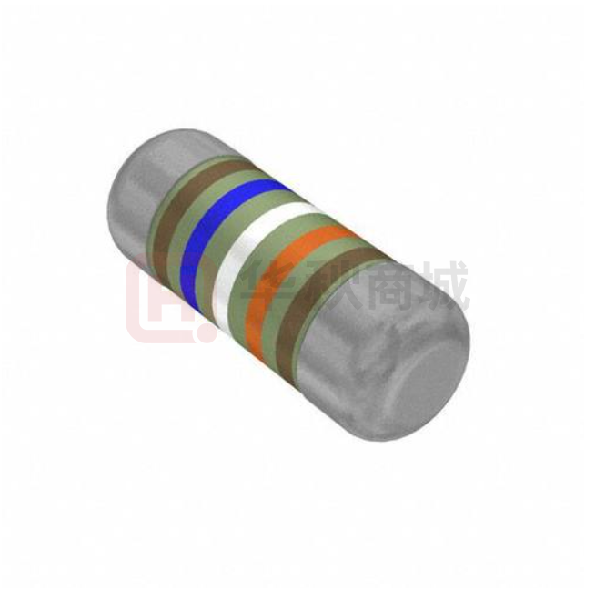
SFP - Stabilized Film
Power MELF Resistor
y
iabilit
tion
• Rel
y
t
Innova
i
l
a
a
n vi
w
Qu
o
t-D
Cos
Specifications Per
D2
• IEC 60115-1
Features
SFP
• Excellent in heat dissipation than chip resistor
• Stronger mechanical structure to endure vibration
and thermal shock
B
D1
L
• Low temperature coefficient and tolerances
• Excellent stability
• Superior power handling
• Products meet RoHS requirements and do not contain
substances of very high concern identified by European
Chemicals Agency
DIMENSIONS
Body Length
(L, mm)
Type
Cap Diameter
(D1, mm)
Body Diameter
(D2, mm)
Soldering Spot
(B, mm)
Net Weight
Per 1000 pcs
SFP204
3.52 ± 0.15
1.35 ± 0.1
D1+0.02/ -0.15
0.6 Min.
17 grams
SFP101
5.90 ± 0.20
2.20 ± 0.1
D1+0.02/ -0.15
1.0 Min.
66 grams
SFP201
8.50 ± 0.50
3.00 ± 0.2
D1+0.02/ -0.15
1.3 Min.
186 grams
SFP301
10.5 ± 0.50
4.00 ± 0.5
D1+0.02/ -0.15
1.6 Min.
446 grams
GENERAL SPECIFICATIONS
Type
Power
Rating*
Maximum
Working
Voltage
Maximum
Overload
Voltage
Minimum
Resistance
Maximum
Resistance
Resistance
Tolerance
Available
Resistance
Values
SFP204
0.4W
200V
400V
0, 0.5Ω
10MΩ
±0.5%~5%
E-192/E-24
SFP101
1W
350V
700V
0, 0.5Ω
10MΩ
±0.5%~5%
E-192/E-24
SFP201
2W
400V
800V
0, 0.5Ω
1MΩ
±0.5%~5%
E-192/E-24
SFP301
3W
400V
800V
0, 0.5Ω
1MΩ
±0.5%~5%
E-192/E-24
* At 70°C, with the exception of SFP201 and SFP301, derating of which starts at 40°C. Please refer to the Power Derating Curve.
* Special sizes, values, and specifications not listed available on special order.
POWER DERATING CURVE
100%
90%
SFP204, SFP101
80%
SFP201
SFP301
RATED
LOAD
70%
60%
50%
40%
30%
20%
10%
0%
30
40
50
60
70
80
90
100
110
120
130
140
150
160
o
AMBIENT TEMPERATURE ( C)
151
www.firstohm.com.tw
qrc@firstohm.com.tw
Revision: 25-APRIL-2023
�SFP - Stabilized Film
Power MELF Resistor
y
iabilit
tion
• Rel
y
t
Innova
i
l
a
a
n vi
w
Qu
o
t-D
Cos
SFP
SUGGESTED PAD LAYOUT
Type
SFP204
SFP101
SFP201
SFP301
Soldering Mode
Pad Length
(L, mm, Min.)
Pad Spacing
(P, mm)
Pad Width
(W, mm, Min.)
Reflow
1.3
1.6 ± 0.1
1.6
Wave
1.5
1.5 ± 0.1
1.8
Reflow
2.0
3.0 ± 0.1
3.0
Wave
2.5
3.0 ± 0.1
3.0
Reflow
3.0
4.9 ± 0.3
3.7
Wave
3.5
4.8 ± 0.3
4.0
Reflow
4.0
6.2 ± 0.4
5.0
Wave
4.5
6.0 ± 0.4
5.0
For better heat dissipation / lower heat resistance, increase W & L.
COVER TAPE PEELING SPECIFICATION
Recommended peeling force: SFP204, SFP101: 50±5gf
Revision: 25-APRIL-2023
SFP201, SFP301: 70±10gf
www.firstohm.com.tw
qrc@firstohm.com.tw
152
�SFP - Stabilized Film
Power MELF Resistor
y
iabilit
tion
• Rel
y
t
Innova
i
l
a
a
n vi
w
Qu
o
t-D
Cos
PART NUMBER
SFP
Example: SFP101F46R4TKSTR2K0
SFP101
F
46R4
TKS
TR2K0
Type
Tolerance*
Resistance
TCR*
Packaging
Z (Jumper)
D (0.5%)
F (1%)
G (2%)
J (5%)
46.4Ω
4-character code
containing 3 significant digits
1 letter multiplier
100ppm
3-character code
5-character code
OHM MULTIPLIER
R=1
K = 103
M = 106
G = 109
TKQ = ± 25 ppm
TKR = ± 50 ppm
TKS = ± 100 ppm
TK2 = ± 200 ppm
TR = Tape Reel
(pieces per reel)
SFP204
3K0 = 3,000
6K0 = 6,000**
10K = 10,000**
SFP101
2K0 = 2,000
6K0 = 6,000**
10K = 10,000**
SFP201
2K5 = 2,500
SFP301
2K0 = 2,000
* Listed values may not be applicable across product types or to all resistance values. Please check with us before placing order.
** upon request
TECHNICAL SUMMARY
Characteristics
Limits
Dielectric Withstanding Voltage, VAC or DC
SFP204: 200
SFP101: 500
SFP201: 700
SFP301: 1000
Temperature Coefficient, PPM / °C*
±25, ±50, ±100, ±200
Operating Temperature Range, °C
-55 ~ +155
Insulation Resistance, MΩ
>104
Failure Rate in Time, pcs / 109 device hours
SFP101J68K0TKRTR2K0 价格&库存
很抱歉,暂时无法提供与“SFP101J68K0TKRTR2K0”相匹配的价格&库存,您可以联系我们找货
免费人工找货