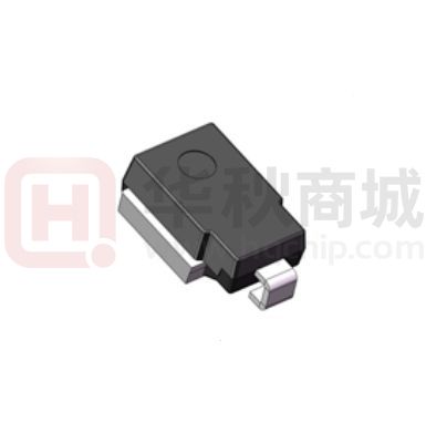
SM8S10(C)A thru SM8S43(C)A
Stand-off Voltage - 10 to 43 Volts
Surface Mount Transient Voltage Suppressors
High Temperature Stability and High Reliability Conditions
Features
• Round chip produced by chemical method
• Junction passivated by polyimide
• TJ = 175 °C capability suitable for high reliability and
automotive requirement
• Available in uni-directional and bi-directional polarity
• Low leakage current
• Low forward voltage drop
• High surge capability
• Meets ISO7637-2 surge specification (varied by test
condition)
• Meets MSL level 1, per J-STD-020, LF maximum peak of
245 °C
DO-218AB
• AEC-Q101 qualified
MECHANICAL DATA
TYPICAL APPLICATIONS
Case: DO-218AB
Molding compound meets UL 94 V-0 flammability rating
Base P/NHE3_X - RoHS-compliant and AEC-Q101 qualified
(“X” denotes revision code e.g. A, B, ...)
Use in sensitive electronics protection against voltage
transients induced by inductive load switching and lighting,
especially for automotive load dump protection application.
Terminals: matte tin plated
J-STD-002 and JESD 22-B102
leads,
solderable
per
Polarity: heatsink is anode
Package: DO-218AB
Maximum Ratings and Electrical characteristics
Ratings at 25 °C ambient temperature unless otherwise specified.
Parameter
Peak pulse power dissipation
with 10/1000 μs waveform
with 10/10 000 μs waveform
Power dissipation on infinite heatsink at TC = 25 °C (fig. 1)
Symbol
PPPM
Value
6600
5200
Unit
W
PD
8.0
W
IPPM (1)
See next table
A
Peak forward surge current 8.3 ms single half sine-wave
IFSM
700
A
Typical thermal resistance, junction to case
RJC
0.90
°C/W
TJ, TSTG
-55 to +175
°C
Peak pulse current with 10/1000 μs waveform
Operating junction and storage temperature range
Note
(1) Non-repetitive current pulse derated above T = 25 °C
A
DN:T21702A0
http://www.microdiode.com
Rev:2021A0
Page :1
�SM8S10(C)A thru SM8S43(C)A
Stand-off Voltage - 10 to 43 Volts
ELECTRICAL CHARACTERISTICS (TC = 25 °C unless otherwise noted)
BREAKDOWN
VOLTAGE
VBR (V)
DEVICE
TYPE
TEST
STAND-OFF
CURRENT
IT
VOLTAGE
MAXIMUM
REVERSE
AT VWM
ID (μA)
MAXIMUM
REVERSE
LEAKAGE
AT VWM
TJ = 175 °C
ID (μA)
MAX. PEAK
PULSE CURRENT
AT 10/1000 μs
WAVEFORM
(A)
MAXIMUM
CLAMPING
VOLTAGE
AT IPPM
VC (V)
LEAKAGE
TYPICAL TEMP.
COEFFICIENT
OF VBR (1)
T
(%/°C)
(mA)
VWM
(V)
12.3
5.0
10.0
15
250
388
17.0
0.069
12.9
13.5
5.0
11.0
10
150
363
18.2
0.072
13.3
14.0
14.7
5.0
12.0
10
150
332
19.9
0.074
SM8S13CA
14.4
15.2
15.9
5.0
13.0
10
150
307
21.5
0.076
SM8S14A
SM8S14CA
15.6
16.4
17.2
5.0
14.0
10
150
284
23.2
0.078
SM8S15A
SM8S15CA
16.7
17.6
18.5
5.0
15.0
10
150
270
24.4
0.080
SM8S16A
SM8S16CA
17.8
18.8
19.7
5.0
16.0
10
150
254
26.0
0.081
SM8S17A
SM8S17CA
18.9
19.9
20.9
5.0
17.0
10
150
239
27.6
0.082
SM8S18A
SM8S18CA
20.0
21.1
22.1
5.0
18.0
10
150
226
29.2
0.083
SM8S20A
SM8S20CA
22.2
23.4
24.5
5.0
20.0
10
150
204
32.4
0.085
SM8S22A
SM8S22CA
24.4
25.7
26.9
5.0
22.0
10
150
186
35.5
0.086
SM8S24A
SM8S24CA
26.7
28.1
29.5
5.0
24.0
10
150
170
38.9
0.087
SM8S26A
SM8S26CA
28.9
30.4
31.9
5.0
26.0
10
150
157
42.1
0.088
SM8S28A
SM8S28CA
31.1
32.8
34.4
5.0
28.0
10
150
145
45.4
0.089
SM8S30A
SM8S30CA
33.3
35.1
36.8
5.0
30.0
10
150
136
48.4
0.090
SM8S33A
SM8S33CA
36.7
38.7
40.6
5.0
33.0
10
150
124
53.3
0.091
SM8S36A
SM8S36CA
40.0
42.1
44.2
5.0
36.0
10
150
114
58.1
0.091
SM8S40A
SM8S40CA
44.4
46.8
49.1
5.0
40.0
10
150
102
64.5
0.092
SM8S43A
SM8S43CA
47.8
50.3
52.8
5.0
43.0
10
150
95.1
69.4
0.093
Uni.
Bi.
MIN.
NOM.
MAX.
SM8S10A
SM8S10CA
11.1
11.7
SM8S11A
SM8S11CA
12.2
SM8S12A
SM8S12CA
SM8S13A
Notes
• For all types maximum VF = 1.8 V at IF = 100 A measured on 8.3 ms single half sine-wave or equivalent square wave, duty cycle = 4 pulses
per minute maximum
(1) To calculate V
BR vs. junction temperature, use the following formula: VBR at TJ = VBR at 25 °C x (1 + T x (TJ - 25))
http://www.microdiode.com
Rev:2021A0
Page :2
�SM8S10(C)A thru SM8S43(C)A
Stand-off Voltage - 10 to 43 Volts
RATINGS AND CHARACTERISTICS CURVES (TA = 25 °C unless otherwise noted)
10 000
Reverse Surge Power (W)
Power Dissipation (W)
8.0
6.0
4.0
2.0
1000
0
50
0
150
100
200
Pulse Width (ms) - ½ IPP Exponential Waveform
Fig. 1 - Power Derating Curve
Fig. 4 - Reverse Power Capability
100
Transient Thermal Impedance (°C/W)
6000
Load Dump Power (W)
5000
4000
3000
2000
1000
0
50
25
75
100
150
125
RθJA
10
RθJC
1
0.1
0.01
0.01
175
0.1
1
10
100
Case Temperature (°C)
t - Pulse Width (s)
Fig. 2 - Load Dump Power Characteristics
(10 ms Exponential Waveform)
Fig. 5 - Typical Transient Thermal Impedance
tr = 10 μs
100 000
TJ = 25 °C
Pulse Width (td) is
Defined as the Point
Where the Peak Current
Decays to 50 % of IPPM
Peak Value
IPPM
CJ - Junction Capacitance (pF)
150
Input Peak Pulse Current (%)
100
10
Case Temperature (°C)
100
Half Value - IPP
IPPM
2
50
TJ = 25 °C
f = 1.0 MHz
Vsig = 50 mVp-p
Measured at Zero Bias
10 000
Measured at Stand-Off
Voltage VWM
td
0
1000
0
10
20
30
40
10
15
20
25
30
35
40
t - Time (ms)
VWM - Reverse Stand-Off Voltage (V)
Fig. 3 - Pulse Waveform
Fig. 6 - Typical Junction Capacitance
http://www.microdiode.com
Rev:2021A0
45
Page :3
�SM8S10(C)A thru SM8S43(C)A
Stand-off Voltage - 10 to 43 Volts
PACKAGE OUTLINE DIMENSIONS (millimeters)
DO-218AB
Mounting Pad Layout
ORDERING INFORMATION (Example)
PREFERRED P/N
UNIT WEIGHT (g)
SM8S
2.600
http://www.microdiode.com
PACKAGE
DO-218
BASE QUANTITY
NA
DELIVERY MODE
According to customer's requirement
Rev:2021A0
Page :4
�
很抱歉,暂时无法提供与“SM8S33CA”相匹配的价格&库存,您可以联系我们找货
免费人工找货- 国内价格
- 1+8.31060
- 10+6.62796
- 30+5.71482
- 100+4.66830
