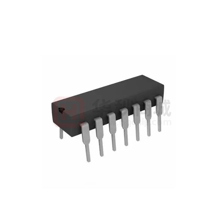
XBLW SN74HC/HCT21
4-Input AND iunction
General Description
The SN74HC/HCT21 provide the 4-input AND function. Inputs include clamp diodes. This enables the use of current
limiting resistors to interface inputs to voltages in excess of VCC.
Features
Input levels:
For SN74HC21: CMOS level
For SN74HCT21: TTL level
Low-power dissipation
Specified from -40℃ to +125℃
Packaging information: DIP14/SOP14/TSSOP14
Ordering Information
Product Model
XBLW SN74HC21N
XBLW SN74HC21DTR
XBLW SN74HC21TDTR
XBLW SN74HCT21N
XBLW SN74HCT21DTR
XBLW SN74HCT21TDTR
Package Type
DIP-14
SOP-14
TSSOP-14
DIP-14
SOP-14
TSSOP-14
Marking
74HC21N
74HC21
74HC21
74HCT21N
74HCT21
74HCT21
Packing
Tube
Tape
Tape
Tube
Tape
Tape
Packing Qty
1000Pcs/Box
2500Pcs/Reel
3000Pcs/Reel
1000Pcs/Box
2500Pcs/Reel
3000Pcs/Reel
Block Diagram And Pin Description
2.1
Block Diagram
Figure 1. Logic symbol
Figure 2. IEC logic symbol
XBLWversion1.0
www.xinboleic.com Technical Support:4009682003
Support:4009682003
1 / 11
�XBLW SN74HC/HCT21
4-Input AND iunction
Figure 3. Logic diagram
Figure 4. Functional diagram
Pin Configurations
Pin Description
Pin No.
1
Pin Name
Description
1A
data input
2
1B
data input
3
4
n.c.
1C
not connected
data input
5
1D
data input
6
1Y
data output
7
GND
ground (0V)
8
2Y
data output
9
2A
data input
10
2B
data input
11
12
n.c.
2C
not connected
data input
13
2D
data input
14
VCC
supply voltage
XBLWversion1.0
www.xinboleic.com Technical Support:4009682003
Support:4009682003
2 / 11
�XBLW SN74HC/HCT21
4-Input AND iunction
Function Table
Input
Output
nA
nB
nC
nD
nY
L
X
X
X
L
X
L
X
X
L
X
X
L
X
L
X
X
X
L
L
H
H
H
H
H
Note: H=HIGH voltage level; L=LOW voltage level; X = don’t care.
Electrical Parameter
Absolute Maximum Ratings
(Voltages are referenced to GND (ground=0V), unless otherwise specified.)
Parameter
Symbol
supply voltage
VCC
Conditions
Min.
-0.5
Max.
Unit
V
mA
input clamping current
IIK
VIVCC+0.5V
output clamping current
IOK
-
+7
±20
VOVCC+0.5V
mA
output current
IO
-
±20
-0.5V
很抱歉,暂时无法提供与“SN74HC21N”相匹配的价格&库存,您可以联系我们找货
免费人工找货