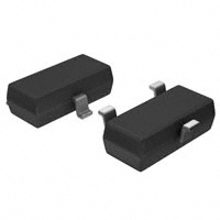
AO3402
SOT-23 Plastic-Encapsulate MOSFETS
30V N-Channel MOSFET
V(BR)DSS
28 mΩ@10V
30V
SOT-23
ID
RDS(on)MAX
3
5A
34 mΩ@4.5V
1. GATE
2. SOURCE
1
3. DRAIN
Features
Lead free product is acquired
Surface mount package
2
Equivalent circuit
MARKING
D
A29T
G
S
PACKAGE SPECIFICATIONS
Package Reel Size
SOT-23
7'
Reel DIA.
(mm)
Q'TY/Reel
(pcs)
Box Size
(mm)
QTY/Box
(pcs)
178
3000
203×203×195
45000
Carton Size Q'TY/Carton
(mm)
(pcs)
438×438×220
180000
Maximum Ratings and Thermal Characteristics (TA = 25°C unless otherwise noted)
Parameter
Symbol
Limit
Drain-Source Voltage
VDS
30
Gate-Source Voltage
VGS
±16
TA=25℃
Continuous Drain Current
Maximum Power Dissipation
2)
Pulsed Drain Current 1)
Operating Junction and Storage Temperature Range
Thermal Resistance Junction-Ambient
TA=70℃
TA=25℃
TA=70℃
V
5.0
ID
A
4
1.5
PD
W
0.9
IDM
TJ, Tstg
Unit
A
20.4
o
-50 to 150
RθJA
80
C
o
C/W
Notes
1) Pulse width limited by maximum junction temperature.
2) Surface Mounted on FR4 Board, t v 5 sec.
The above data are for reference only.
DN:T19C31A0
http://www.microdiode.com
Rev:2019A0
Page :1
�AO3402
MOSFET ELECTRICAL CHARACTERISTICS
Ta =25 ℃ unless otherwise specified
Symbol
Parameter
Test Condition
Min.
Typ.
Miax.
Unit
Static
Drain-Source Breakdown Voltage
Drain-Source On-State Resistance
Gate Threshold Voltage
BVDSS
1)
RDS(on)
VGS(th)
VGS = 0V, ID = 250uA
V
30
VGS = 10V, ID = 4.0A
28
36
VGS = 4.5V, ID = 3.0A
34
50
VGS = 2.5V, ID = 1.0A
55
80
0.8
1.2
V
VDS =VGS, ID = 250uA
0.5
mΩ
Zero Gate Voltage Drain Current
IDSS
VDS=30V, VGS=0V
1
uA
Gate Body Leakage
IGSS
VGS=±16V, VDS=0V
100
nA
gfs
VDS =15V, ID = 4A
Forward Transconductance
1)
S
8
Dynamic
Total Gate Charge
Qg
Gate-Source Charge
Qgs
Gate-Drain Charge
Qgd
Turn-On Delay Time
td(on)
Turn-On Rise Time
tr
Turn-Off Delay Time
td(off)
Turn-Off Fall Time
tf
Input Capacitance
Ciss
Output Capacitance
Coss
Reverse Transfer Capacitance
Crss
Source drain current(Body Diode)
ISD
Diode Forward Voltage
VSD
1)
VDS = 15V, ID = 4A
VGS = 4.5V
3.1
nC
0.4
1.3
4.4
VDD = 15V, RG=3.3 Ω
2.6
ID =1A,VGS = 10V
25.5
ns
3.3
VDS = 15V, VGS = 0V
f = 1.0 MHz
IS = 4.0A, VGS = 0V
240
pF
35
30
0.85
1.8
A
1.2
V
Pulse test : Pulse width≤300µs, duty cycle≤2%.
http://www.microdiode.com
Rev:2019A0
Page :2
�AO3402
ID, Drain-Source Current (A)
VGS(TH), Gate -Source Voltage (V)
Typical Characteristics
VDS, Drain -Source Voltage (V)
Fig2. Normalized Threshold Voltage Vs. Temperature
Rdson, On -Resistance (mΩ))
ID, Drain-Source Current (A)
Fig1. Typical Output Characteristics
Tj - Junction Temperature (°C)
VGS, Gate -Source Voltage (V)
ID , Drain Current (A)
Fig4. On-Resistance vs. Drain Current and Gate
-ID - Drain Current (A)
ISD, Reverse Drain Current (A)
Fig3. Typical Transfer Characteristics
VSD, Source-Drain Voltage (V)
Fig5. Typical Source-Drain Diode Forward Voltage
http://www.microdiode.com
VDS, Drain -Source Voltage (V)
Fig6. Maximum Safe Operating Area
Rev:2019A0
Page :3
�AO3402
C, Capacitance (pF)
VGS, Gate-Source Voltage (V)
Typical Characteristics
VDS, Drain-Source Voltage (V)
Qg, Total Gate Charge (nC)
Fig8. Typical Gate Charge Vs. Gate-Source Voltage
Thermal Resistance
ZqJA Normalized Transient
Fig7. Typical Capacitance Vs. Drain-Source Voltage
Pulse Width (s)
Fig9. Normalized Maximum Transient Thermal Impedance
Fig10. Switching Time Test Circuit and waveforms
The curve above is for reference only.
http://www.microdiode.com
Rev:2019A0
Page :4
�AO3402
Outlitne Drawing
SOT-23 Package Outline Dimensions
1
e
Suggested Pad Layout
0.037
0.95
0.037
0.95
L
L1
E
E1
θ
Symbol
A
A1
b
c
D
E
E1
e
L
L1
θ
Dimensions In Millimeters
Min
Typ
Max
0.90
1.40
0.10
0.00
0.30
0.50
0.20
0.08
2.80
2.90
3.10
1.20
1.60
2.80
2.25
1.80
1.90
2.00
0.10
0.50
0.4
0°
0.55
10°
Note:
1.Controlling dimension:in/millimeters.
2.General tolerance: ±0.05mm.
3.The pad layout is for reference purposes only.
0.079
2.0
0.035
0.9
0.031
0.8
https://www.microdiode.com
inches
mm
Rev:2019A0
Page :5
�
很抱歉,暂时无法提供与“AO3402”相匹配的价格&库存,您可以联系我们找货
免费人工找货- 国内价格
- 20+0.78380
- 100+0.46750
- 800+0.32730
- 3000+0.23380
- 6000+0.22210
- 30000+0.20570
- 国内价格
- 10+0.41740
- 100+0.33390
- 300+0.29140
- 3000+0.25500
- 9000+0.23850
- 21000+0.22650
- 国内价格
- 10+0.37696
- 100+0.30914
- 300+0.27527
- 3000+0.21106
- 6000+0.19074
- 9000+0.18058
