AS3606/7
Preliminary Application Note - Confidential
AS3606/7 – AN01 - Evalboard
System PMU with HV Back Light Driver
1 General Description
The AS3606/07 is an ultra compact System PMU with
integrated battery charger and HV back light driver.
The device offers advanced power management functions.
All necessary ICs and peripherals in a battery
powered mobile device are supplied by the AS3606/07.
It features 3 DCDC converters as well as 5 low noise
LDOs.
The different regulated supply voltages are programmable
via the serial control interface.
The step-up converter for the backlight can operate up
to 26V. Both constant voltage (OLED supply) as well as
constant current (white LED backlight) operations with 2
current sinks are possible. An internal voltage protection
is limiting the output voltage in the case of external component
failures.
AS3606/07 also contains a Li-Ion battery charger with
constant current and constant voltage. The maximum
charging current is 1A. An integrated battery switch and
an optional external switch are separating the battery
during charging or whenever an external power supply
is present. With this switch it is also possible to operate
with no or deeply discharged batteries. A programmable
current limit can be used to control the maximum current
used from a USB supply.
The single supply voltage may vary from 2.7V to 5.5V.
www.austriamicrosystems.com (dgm)
Revision 1v1 / 20100309
1 - 19
�AS3606/7
Preliminary Application Note - Confidential
Table of Contents
1
GENERAL DESCRIPTION................................................................................................................. 1
2
OTHER APPLICABLE DOCUMENTS AND PAPERS........................................................................... 3
3
FURTHER APPLICATIONS ............................................................................................................... 3
4
REVISION STATUS .......................................................................................................................... 3
5
GENERAL DESCRIPTION................................................................................................................. 3
6
GETTING STARTED ......................................................................................................................... 4
6.1
6.2
6.3
AS3606/07 Demo Software Installation .................................................................................................... 4
Connecting the Evalboard and USB Box with the PC............................................................................... 5
Starting the AS3607 Demo software......................................................................................................... 6
7
AS3607 EVALBOARD 1V0 CONNECTOR AND JUMPER LOCATIONS ............................................... 7
8
APPLICATION SCHEMATIC OF AS3607 EVALBOARD 1V0............................................................... 9
9
AS3607 EVALBOARD 1V0: LAYOUT (TOP VIEW) ........................................................................... 11
10
AS3607 EVALBOARD 1V0: LAYOUT (MID LAYER 1) ...................................................................... 11
11
AS3607 EVALBOARD 1V0: LAYOUT (MID LAYER 2) ...................................................................... 12
12
AS3607 EVALBOARD 1V0: LAYOUT (BOTTOM VIEW) ................................................................... 12
13
AS3606 EVALBOARD 1V1 CONNECTOR AND JUMPER LOCATIONS ............................................. 13
14
APPLICATION SCHEMATIC OF AS3606 EVALBOARD 1V1............................................................. 15
15
AS3606 EVALBOARD 1V1: LAYOUT (TOP VIEW) ........................................................................... 17
16
AS3606 EVALBOARD 1V1: LAYOUT (MID LAYER 1) ...................................................................... 17
17
AS3606 EVALBOARD 1V1: LAYOUT (MID LAYER 2) ...................................................................... 18
18
AS3606 EVALBOARD 1V1: LAYOUT (BOTTOM VIEW) ................................................................... 18
COPYRIGHT ........................................................................................................................................... 19
www.austriamicrosystems.com (dgm)
Revision 1v1 / 20100309
2 - 19
�AS3606/7
Preliminary Application Note - Confidential
2 Other applicable documents and papers
Data Sheet: AS3607 0v1
3 Further Applications
Applications based on the AS3607 are continuously updated. Visit our home-page:
http: //www.austriamicrosystems.com
4 Revision status
AS3607_AN01_Evalboard Application note (this document):
AS3607 Evalboard schematic:
AS3607 Evalboard layout
AS3606 Evalboard schematic:
AS3606 Evalboard layout
Rev.: 1v1
Rev.: 1v0
Rev.: 1v0
Rev.: 1v1
Rev.: 1v1
5 General description
Remark: all subsequent component numbering refers to the application schematics, shown in pt. Application
Schematic.
www.austriamicrosystems.com (dgm)
Revision 1v1 / 20100309
3 - 19
�AS3606/7
Preliminary Application Note - Confidential
6 Getting Started
6.1 AS3606/07 Demo Software Installation
Start the demo software Installation Shield with “Install Demo Software”.
The Install Shield will guide you through the rest of the installation.
www.austriamicrosystems.com (dgm)
Revision 1v1 / 20100309
4 - 19
�AS3606/7
Preliminary Application Note - Confidential
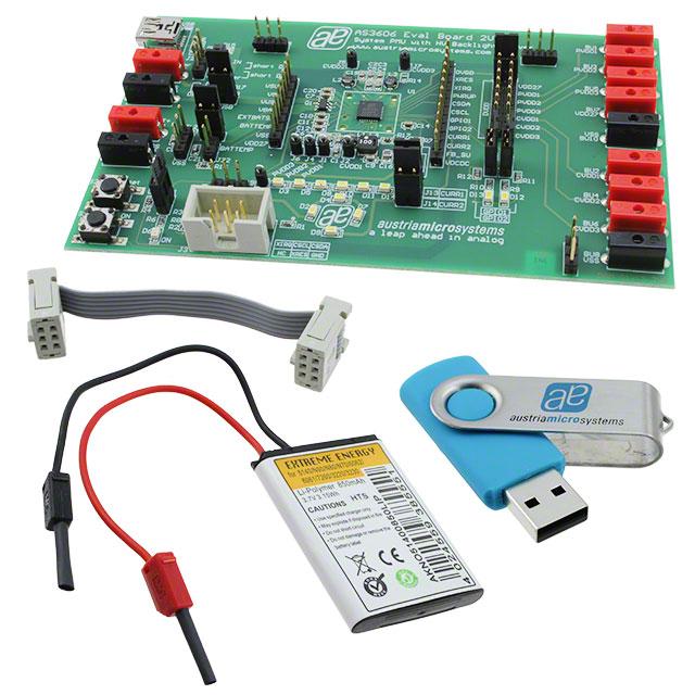
6.2 Connecting the Evalboard and USB Box with the PC
After the successful installation of the demo software, the USB Box can be connected to the PC and to the
Evalboard as shown in the picture below.
www.austriamicrosystems.com (dgm)
Revision 1v1 / 20100309
5 - 19
�AS3606/7
Preliminary Application Note - Confidential
6.3 Starting the AS3607 Demo software
The correct installed demo software can be started from Start > Programs > austriamicrosystems > AS3607
EvalSW.
USB connection is immediately indicated in the status bar of the demo software.
www.austriamicrosystems.com (dgm)
Revision 1v1 / 20100309
6 - 19
�AS3606/7
Preliminary Application Note - Confidential
7 AS3607 Evalboard 1V0 connector and jumper locations
Listed below are the various connectors and jumpers.
Jumper
J1
J2
J3
J4
J5
J6
J7
J8
J9
J10
J11
J12
J13
J14
J15
J16
J17
J18
J20
J21
J22
J23, J24,
J26,J27
J25
J29,J30
BU1 –
BU7
BU9
U2
B12
B13
B8,B10,
B13
S1
S2
comment
Function
PVDD1
CVDD1
I2C Interface
PVDD2
CVDD2
PVDD3
CVDD3
PVDD4
I USB
measurement pinhead
ON LED
VBAT
CURR1
CURR2
GPIO1
GPIO2
measurement pinhead
I BAT
DVDD
regulator output
BATTEMP
VSS
disable protection jumper
GPIO3, GPIO4
LDO and DCDC converter output
measurement pinhead of LDO PVDD1
measurement pinhead of DCDC CVDD1
USB-Box connector
measurement pinhead of LDO PVDD2
measurement pinhead of DCDC CVDD2
measurement pinhead of LDO PVDD3
measurement pinhead of DCDC CVDD3
measurement pinhead of LDO PVDD4
current measurement jumper of charge current
status LED connected to VDD27
Battery voltage measurement pinhead
current measurement jumper of CURR1
current measurement jumper of CURR2
if set, LED D12 is connected to GPIO1
if set, LED D13 is connected to GPIO2
current measurement jumper of battery current
DVDD can be supplied with one of the regulators; default: set to VDD27
DVDD can be supplied with one of the regulators; default: set to VDD27
if set, pull up resistor is connected to GPIO3/4
Charger input
Charger input
VBAT+
VBATVSS
Charger input: 2mm connector
Charger input: USB connector
Battery connector
Battery connector
ON
Reset
ON button
Reset button
www.austriamicrosystems.com (dgm)
Revision 1v1 / 20100309
7 - 19
�AS3606/7
Preliminary Application Note - Confidential
Connector and Jumper locations of AS3607 Eval Board 1V0
www.austriamicrosystems.com (dgm)
Revision 1v1 / 20100309
8 - 19
�www.austriamicrosystems.com (dgm)
Revision 1v1 / 20100309
9 - 19
Application Schematic AS3607 Evalboard 1v0- page 1
8 Application Schematic of AS3607 Evalboard 1v0
Preliminary Application Note - Confidential
AS3606/7
�www.austriamicrosystems.com (dgm)
Preliminary Application Note - Confidential
AS3606/7
Revision 1v1 / 20100309
10 - 19
Application Schematic AS3607 Evalboard 1v0 – page2
�AS3606/7
Preliminary Application Note - Confidential
9 AS3607 Evalboard 1v0: Layout (top view)
Layout (top view)
10 AS3607 Evalboard 1v0: Layout (mid layer 1)
Layout (mid1 view)
www.austriamicrosystems.com (dgm)
Revision 1v1 / 20100309
11 - 19
�AS3606/7
Preliminary Application Note - Confidential
11 AS3607 Evalboard 1v0: Layout (mid layer 2)
Layout (mid2 view)
12 AS3607 Evalboard 1v0: Layout (bottom view)
Layout (bottom view)
www.austriamicrosystems.com (dgm)
Revision 1v1 / 20100309
12 - 19
�AS3606/7
Preliminary Application Note - Confidential
13 AS3606 Evalboard 1V1 connector and jumper locations
Listed below are the various connectors and jumpers.
Jumper
J1
J2
J3
J4
J5
J6
J7
J9
J10
J11
J12
J13
J14
J15
J16
J17
J18
J20
J21
J22
J23, J24,
J26,J8
J25
BU1 –
BU7
BU9
U2
B12
B13
B8,B10,
B11
S1
S2
comment
Function
PVDD1
CVDD1
I2C Interface
PVDD2
CVDD2
PVDD3
CVDD3
I USB
measurement pinhead
ON LED
VBAT
CURR1
CURR2
GPIO1
GPIO2
measurement pinhead
I BAT
DVDD
regulator output
BATTEMP
VSS
measurement pinhead of LDO PVDD1
measurement pinhead of DCDC CVDD1
USB-Box connector
measurement pinhead of LDO PVDD2
measurement pinhead of DCDC CVDD2
measurement pinhead of LDO PVDD3
measurement pinhead of DCDC CVDD3
current measurement jumper of charge current
status LED connected to VDD27
Battery voltage measurement pinhead
current measurement jumper of CURR1
current measurement jumper of CURR2
if set, LED D12 is connected to GPIO1
if set, LED D13 is connected to GPIO2
current measurement jumper of battery current
DVDD can be supplied with one of the regulators; default: set to VDD27
DVDD can be supplied with one of the regulators; default: set to VDD27
disable protection jumper
LDO and DCDC converter output
Charger input
Charger input
VBAT+
VBATVSS
Charger input: 2mm connector
Charger input: USB connector
Battery connector
Battery connector
ON
Reset
ON button
Reset button
www.austriamicrosystems.com (dgm)
Revision 1v1 / 20100309
13 - 19
�AS3606/7
Preliminary Application Note - Confidential
Connector and Jumper locations of AS3606 Eval Board 1V1
www.austriamicrosystems.com (dgm)
Revision 1v1 / 20100309
14 - 19
�www.austriamicrosystems.com (dgm)
Revision 1v1 / 20100309
15 - 19
Application Schematic AS3606 Evalboard 1v1 – page1
14 Application Schematic of AS3606 Evalboard 1v1
Preliminary Application Note - Confidential
AS3606/7
�www.austriamicrosystems.com (dgm)
Preliminary Application Note - Confidential
AS3606/7
Revision 1v1 / 20100309
16 - 19
Application Schematic AS3606 Evalboard 1v1 – page2
�AS3606/7
Preliminary Application Note - Confidential
15 AS3606 Evalboard 1v1: Layout (top view)
Layout (top view)
16 AS3606 Evalboard 1v1: Layout (mid layer 1)
Layout (mid1 view)
www.austriamicrosystems.com (dgm)
Revision 1v1 / 20100309
17 - 19
�AS3606/7
Preliminary Application Note - Confidential
17 AS3606 Evalboard 1v1: Layout (mid layer 2)
Layout (mid2 view)
18 AS3606 Evalboard 1v1: Layout (bottom view)
Layout (bottom view)
www.austriamicrosystems.com (dgm)
Revision 1v1 / 20100309
18 - 19
�AS3606/7
Preliminary Application Note - Confidential
Copyright
Copyright © 1997-2009, austriamicrosystems AG, Schloss Premstaetten, 8141 Unterpremstaetten, AustriaEurope. Trademarks Registered ®. All rights reserved. The material herein may not be reproduced, adapted,
merged, translated, stored, or used without the prior written consent of the copyright owner.
All products and companies mentioned are trademarks or registered trademarks of their respective companies.
Diclaimer
Devices sold by austriamicrosystems AG are covered by the warranty and patent indemnification provisions
appearing in its Term of Sale. austriamicrosystems AG makes no warranty, express, statutory, implied, or by
description regarding the information set forth herein or regarding the freedom of the described devices from
patent infringement. Austriamicrosystems AG reserves the right to change specifications and prices at any time
and without notice. Therefore, prior to designing this product into a system, it is necessary to check with
austriamicrosystems AG for current information.
This product is intended for use in normal commercial applications. Applications requiring extended temperature
range, unusual environmental requirements, or high reliability applications, such as military, medical life-support
or lifesustaining equipment are specifically not recommended without additional processing by
austriamicrosystems AG for each application. For shipments of less than 100 parts the manufacturing flow might
show deviations from the standard production flow, such as test flow or test location.
The information furnished here by austriamicrosystems AG is believed to be correct and accurate. However,
austriamicrosystems AG shall not be liable to recipient or any third party for any damages, including but not
limited to personal injury, property damage, loss of profits, loss of use, interruption of business or indirect,
special, incidental or consequential damages, of any kind, in connection with or arising out of the furnishing,
performance or use of the technical data herein. No obligation or liability to recipient or any third party shall arise
or flow out of austriamicrosystems AG rendering of technical or other services.
Contact Information
Headquarters
austriamicrosystems AG
A-8141 Schloss Premstätten, Austria
T. +43 (0) 3136 500 0
F. +43 (0) 3136 5692
For Sales Offices, Distributors and Representatives, please visit:
http://www.austriamicrosystems.com/contact
www.austriamicrosystems.com (dgm)
Revision 1v1 / 20100309
19 - 19
�


 工商网监
湘ICP备2023018690号
工商网监
湘ICP备2023018690号
