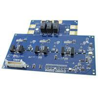
Six Channel SiC MOSFET Driver
Gate Driver for 1200V SiC MOSFET Power Module
Features
6 output channels
Isolated power supply
Direct mount low inductance design
Short circuit protection
Over temperature protection
Under voltage protection
For use with Cree Module
45mm, 6-pak modules.
Applications
6-pak Driver for 1.2kV, SiC MOSFET modules
DC Bus voltage up to 900VDC
Absolute Maximum Ratings
Symbol
Vs
ViH
ViL
IO.pk
IO.avg.ma
x
FMax
Parameter
Visol
Top
Tstg
Supply voltage
Vi
Input signal voltage on/off
Supply current (no load)
Supply current (switching)
Input threshold voltage HIGH
Input threshold voltage LOW
Turn on propogation delay
Turn off propogation delay
Pulse width for resetting fault
Weight
Mean time between failure
ViT+
ViTTdon
Tdoff
Terr
W
MTBF
1
Parameter
VS
ISO
16
5
0
9
2
V
V
V
A
150
1200
kHz
Ouput average current
Characteristics
Symbol
Unit
Power Supply Voltage
Input signal voltage HIGH
Input signal voltage LOW
Output peak current
Max. Switching frequency
Max. Drain to source
voltage
Input to output isolation
voltage
Operating temperature
Storage temperature
VDS
Value
CGD15FB45P Rev -
Part Number
Package
Marking
CGD15FB45P
PCBA
CGD15FB45P Rev2
Test Conditions
Vs ramp rate >50V/sec
A
Vg=+20/-5, Rg = 10
V
±1200
V
-25 to 70
-40 to 85
ºC
ºC
Min
Value
Typ
Max
13.0
15.0
16.0
3.5
800
Note
5/0
330
830
420
1000
210
225
1.5
280
295
300
1.5
Unit
Test Conditions
V
V
mA
V
V
nS
nS
nS
g
6
10 h
70C
70C, 150khz
Notes
�Driver Overview
Block Diagram
Note: Default gate resistor for Rg is 10 for gate ON and OFF. The user can control the gate turn ON and OFF
speed by changing Rg to a lower value and gain better MOSFET switching efficiency. The user can also control the
Gate turn-ON and OFF speed independently by populating Rg.off and D1. Cs is made up of 3x 2.2nF, 1.2kV film
capacitors.
2
CGD15FB45P Rev -
�X1 – 26 pos Signal connector (FCI p/n# 71918-126LF)
1
3
5
7
9
11
13
15
17
19
21
23
25
PWM_Upper_A (5V Logic)
PWM_Lower_A (5V Logic)
PWM_Upper_B (5V Logic)
PWM_Lower_B (5V Logic)
PWM_Upper_C (5V Logic)
PWM_Lower_C (5V Logic)
/RST (normally hi)
RDY (normally hi)
DESAT FAULT (normally low)
OVER_TEMP_FLT (normally low)
2
4
6
8
10
12
14
16
18
20
22
24
26
PWR In (Vs)
LED Status Indicators
L1
L3
L5
L7
RED led, illuminated when
Phase A upper switch has a
desat fault.
RED led, illuminated when
Phase B upper switch has a
desat fault.
RED led, illuminated when
Phase C upper switch has a
desat fault.
GREEN led, illuminated when
power is present and all faults
are clear.
L2
L4
L6
L8
COMMON
RED led, illuminated when
Phase A lower switch has a
desat fault.
RED led, illuminated when
Phase B lower switch has a
desat fault.
RED led, illuminated when
Phase C lower switch has a
desat fault.
RED led, illuminated when there
is an over temp fault.
Fault Handling
Each of the six gate drive channels is protected by a desaturation circuit. In the event of a short circuit,
the voltage across the MOSFET (VDS) rises until it hits a threshold which causes the desaturation circuit
to drive all six gate drive channels to their off state. Pin 17 of the 26 pin main signal connector toggles
high when a desaturation event occurs. There will also be a red LED (L1-L6) illuminated for the gate
drive channel(s) that activated the desaturation protection. Once the fault is cleared, the circuit can be
reset with the onboard reset button or remotely by pulling pin 13 of the 26 pin ribbon connector to
common.
There is an overtemperature protection circuit that turns off all the gates in the event an overtemperature
is detected. The overtemperature circuit reads the value of the six pack module’s onboard NTC. When
the NTC reaches a value corresponding to 115C, the overtemperature circuit is activated and all six gate
drive channels are driven to their low state. Pin 19 of the 26 pin ribbon connector is toggled high when an
overtemperature fault occurs.
3
CGD15FB45P Rev -
�Typical Application
4
CGD15FB45P Rev -
�Mechanical Instructions
Designed to directly mount to Cree 45 mm style power modules, the 6-ch gate driver also has several
other mounting holes to secure the assembly.
Attach the gate driver board to the power module via the 4x Module screw holes (see diagram below)
using the recommended hardware in Table 1. Then solder the 28x solder pins via the solder pin holes to
electrically connect the driver board to the power module. The solder must not exceed 260ºC and the
solder per pin must not exceed 10 seconds. The solder joints should be in accordance with IPC A 610
Rev D (or later) – Class 3 to ensure an optimal connection between the module and gate driver board.
The module plus driver board assembly must be further supported by securing the assembly to standoffs
via the 9x Mounting holes shown in the figure below.
Table 1 Hardware List
Ref
Module
screw holes
Mounting
holes
Access holes
Solder pin
holes
Power
terminals
Description
2.5mm clearance holes for mounting
screws to secure the module to the
printed circuit board assembly.
4.3mm clearance holes for screws to
secure the circuit assembly to standoffs for additional support.
10mm clearance hole to provide
access to the screw that secure the
module to the heatsink.
1.6mm plated holes for solder pins
from power module.
Hardware
5mm holes to secure power cables.
Locations
Torque
M2.5 x 4mm
4x
0.5 Nm
6-32 x 5/6” Zinc Plated pan head
screw /w internal tooth washer.
9x
0.9 Nm
n/a
2x
n/a
Solder pins from power module
28x
n/a
*
7x
* Power terminal holes are sized to accept a PENN broaching nut (#P-KFS2-032). A 10-32, 6mm screw with a
captured lock washer should be used with this broaching nut.
5
CGD15FB45P Rev -
�Mechanical Drawing (units in Inches)
This product has not been designed or tested for use in, and is not intended for use in, applications implanted into the human body
nor in applications in which failure of the product could lead to death, personal injury or property damage, including but not limited
to equipment used in the operation of nuclear facilities, life-support machines, cardiac defibrillators or similar emergency medical
equipment, aircraft navigation or communication or control systems, air traffic control systems, or weapons systems.
Copyright © 2014 Cree, Inc. All rights reserved. The information in this document is subject to change without notice. Cree and the
Cree logo are registered trademarks and Z-REC and Z-FET are trademarks of Cree, Inc.
6
CGD15FB45P Rev -
Cree, Inc.
4600 Silicon Drive
Durham, NC 27703
USA Tel: +1.919.313.5300
Fax: +1.919.313.5451
www.cree.com/power
�
很抱歉,暂时无法提供与“CGD15FB45P”相匹配的价格&库存,您可以联系我们找货
免费人工找货