DIY Remote Control Robot Kit (Support
Android) SKU:COMB0004
Contents
[hide]
1 Overall
o 1.1 Microcontroller
2 Part List
o 2.1 Basic Kit
o 2.2 Upgrade Components
o 2.3 Additional Parts Required
3 Assembly
o 3.1 Basic Platform
o 3.2 Electronocs and Wiring
3.2.1 1 Power and Switch
3.2.2 2 Motors
3.2.3 3 IR Remote Control
3.2.4 4 IR sensors
3.2.5 5 Servo
3.2.6 6 URM37 v3.2 Ultrasonic sensor
3.2.7 7 7LEDs disc
3.2.8 Total
4 Project Ideas
5 Arduino Code
o 5.1 Bluetooth Remote Control
5.1.1 Example
o 5.2 IR Remote Control
o 5.3 Obstacle Avoidance
o 5.4 Sdandard PWM DC control
Overall
This basic robot is intended for you to create a small autonomous or remote controlled robot.
Although the kit includes all essential parts to make an autonomous robot, it is intended to allow you
to add your own electronics in order to satisfy your objectives.
4WD Mobile platform Motors: 7-12V DC
Dimensions: 200mm x 170mm x 105mm
�Microcontroller
Romeo V2-All in one Controller (R3)
Front view
Back view
More information about Romeo
�Part List
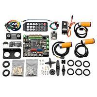
Basic Kit
The following parts are included with the basic platform kit:
Product Code
Name
ROB0003
4WD Mobile Platform (Arduino Controller Supported)
DFR0225
Unit Port Port Type
Romeo‐All in one Controller
1
/
/
20
digital
12
Analog
1
SER0020
DF05BB Standard Servo (5kg)
1
1
digital
DFR0107
IR Kit For Arduino
1
1
digital
FIT0063
10 sets M3 * 10 hexagonal standoffs mounting kit
1
/
/
Upgrade Components
The following parts are included in the upgrade kit, along with all parts in the basic kit:
Product Code
Name
Unit
Port
Port Type
FIT0006
URM ultrasound mounting bracket
1
/
/
SEN0001
URM37 V4.0 Ultrasonic Sensor
1
2
digital
�SEN0019
Adjustable Infrared Sensor Switch
3
1 for each
digital
DFR0106
Light Disc with 7 SMD RGB LED
2
3 for each digital(PWM)
TEL0026
DFRobot Bluetooth V3
1
1
Serial
SER0020
DF05BB Standard Servo (5kg)
1
1
digital
FIT0004
Pan and Tilt Kit (Black Anodized) (no servos)
1
/
/
Additional Parts Required
In order to build the complete kit, you will need the following additional (basic) tools:
Wire cutter and wire stripper
Soldering Iron
Solder
Phillips Screw Driver
Pliers
5xAA batteries (1.2V rechargeable or 1.5V alkaline)
Assembly
Although you can develop your own way to build your robot with the kit, this manual will give you a
basic guide to assembling the robot.
Basic Platform
1. Before assembly the motor, you should solder the motor wires to the motor. Please leave a wire
length of at least 15-20 cm in order to install to Romeo. Be careful when using a soldering iron, heat
shrink tubing is recommended to protect soldered wires.(If you have condition you can use hot glue
to fixed the wires) If you do not know how to use a soldering iron, please find professional help.
2. Insert the two motors into the frame and using the given truss screws secure it. Note the direction
of the motors, ensure the holes line up properly between the motor and truss.
�3. All four motor are installed in the same way mentioned here.
4. The battery holder is installed with countersunk screws on the fuselage’s lower plate.(tips: you
may alternatively use the 7.4V Lipo 2200mAh Battery(FIT0137) at DFRobot to replace the battery
holder).
�5. The battery holder uses five AA batteries. You can use 1.2v rechargeable, or 1.5v alkaline
batteries. We recommend using rechargeable batteries.
6. Before assembly the power switch and power jack, you should solder the wires to the switch and
jack. Please leave at least 10-15 cm of wire in order to install to battery holder and Romeo.
Remember red for positive, black for negative. Again, please be careful when using a soldering iron,
heat shrink tubing is recommended to protect soldered parts. If you do not know how to use a
soldering iron, please find professional help.
7. Please install the power switch and power jack on the bezel as pictured below.
�8. Use the screws to connect the fuselage’s lower plate and motor brackets.
9. Before installing any other parts, you must attach the wheels to the motors. Otherwise you may
risk damage to the motor shafts.
10. Using the screw to fix the side truss to the fuselage’s lower plate.
�11. Use flange screws to fix the fuselage’s upper plate to the side truss.
12. When installing the fuselage upper plate, make sure the battery cables have been identified and
pull the leads out so you can wire them to the Romeo.
13. Use flange screws to fix the sensor mounting grill to the bracket. This grill is an option to use if
you have any other sensors to install.
�14. The copper stand-offs need to be mounted on the fuselage’s upper plate in order to support the
top plate.
15. Use flange screws to fix the IR sensor’s mounting bracket on the top plate.
�16. Use flange screws to fix the top plate on to the Copper stand-offs.
�Electronocs and Wiring
1 Power and Switch
Connect the power supply and switch. Remember that red for positive, and black for negative.
�2 Motors
Connect the two left motor to M1 and the two right motor to M2. When you connect the motors you
should test the motors for each side to ensure they move in the right direction. If not, you should flip
the wiring for only one of the motors.
3 IR Remote Control
Connect the IR receiver to digital pin 3, the green line is for data, the black line is for GND, and the
red line is for Vcc.
�4 IR sensors
Connect the IR sensors to analog pins 2, 3 and 4. You have to re-wire the connectors to fit the
analog pins (Notice the wire order). If you don’t want to use the analog pins, you can just plug into
digital pins but you should note that in this setup most of the digital pins are used to drive other
sensors and the motors.
5 Servo
Connect the servo to digital pin 12, the orange(Blue in picture) line is for the data, the brown(Black in
picture) line is for GND, the red line is for Vcc.
�6 URM37 v3.2 Ultrasonic sensor
Connect the URM sensor to digital pins 8 (blue), and 13(green), the red line is for 5V+, the black line
is for GND.
7 7LEDs disc
Connect the 7LEDs disc to digital pins 9(green), 10(red), and 11(blue), and GND (black) to GND.
�Total
When all of the sub-section tests have passed, you should end up with something that looks just like
the diagram below. A little mess somehow.:-D
�Project Ideas
The basic robot is intended for you to create a small autonomous or remote controlled robot.
Although the kit includes all essential parts to make an autonomous robot, it is intended to allow you
to add your own electronics in order to satisfy your objectives.
1 Blutooth Remote Control
We have created some sample code so that you can use your mobile phone with the Bluetooth to
control the robot. (Sample code at the end of this document)
2 IR Remote Control
We have lots of IR controllers in the home for TVs, DVDs, Blu-rays, etc… And we have provided a
sample code which you can modify to use your existing IR controls to control your robot.
3 Obstacle Avoidance
Giving a robot life is amazing. The great thing is that you can make your robot have its own
personality. You can program it to react to obstacles in its own unique way. We provide some
sample codes you can use to understand how the robot operates and observe its DFRobot
personality.
Arduino Code
The following demo code is compiled in the Arduino IDE (download from Arduino) and uses two
subroutines. You are free to copy/paste the code into the Arduino compiler. Ensure the motor
controller is connected properly before use.
Bluetooth Remote Control
Here, you could upload the code below to your controller, then apply your BLE or bluetooth 2.0
devices on your controller. With an App called bluetooth serial assistant on your phone (Android or
IOS, not Win), you could control your robot car through the key_w a s d to control the run direction
and q to stop the car.
/*
Bluetooth PWM control
NOTE:set your BT rate 115200
//BT(bluetooth)
Apply the BT on your romeo, using the phone BT as the controler.
Could realize the 4 direction control with key "a" "s" "d" "w"
and Stop with "q" .
http://www.dfrobot.com/index.php?route=common/store_home
http://www.dfrobot.com.cn/community/portal.php
created on 17 Mar 2015
�by Leff Wei @DFRobot
*/
int E1 = 5;
//define M1 enable pin
int E2 = 6;
//define M2 enable pin
int M1 = 4;
//define M1 speed pin
int M2 = 7;
//define M2 speed pin
void stop(void){
//stop
digitalWrite(E1,LOW);
digitalWrite(E2,LOW);
}
void advance(char a,char b){
analogWrite (E1,a);
//forward
//PWM speed control
digitalWrite(M1,HIGH);
analogWrite (E2,b);
digitalWrite(M2,HIGH);
}
void back_off (char a,char b) {
//back
analogWrite (E1,a);
digitalWrite(M1,LOW);
analogWrite (E2,b);
digitalWrite(M2,LOW);
}
void turn_L (char a,char b) {
//turn left
analogWrite (E1,a);
digitalWrite(M1,LOW);
analogWrite (E2,b);
digitalWrite(M2,HIGH);
}
void turn_R (char a,char b) {
analogWrite (E1,a);
digitalWrite(M1,HIGH);
analogWrite (E2,b);
//turn right
�digitalWrite(M2,LOW);
}
void setup(void) {
int i;
for(i=4;i0){
//if received data from Bluetooth
char val = Serial1.read();
//if(Serial.available()>0){
//Control the platform via Bluetooth
//if received data from serial port
//char val = Serial.read();
//Control the platform via USB cable
Serial.print("The command you input is:"); // display the command on your
IDE monitor
Serial.println(val);
if(val!=-1){
switch(val){
case 'w'://forward
advance (100,100);
break;
case 's'://backward
back_off (100,100);
break;
case 'a'://turn left
turn_L (100,100);
break;
case 'd'://turn right
turn_R (100,100);
break;
//PWM speed control
�case 'q'://stop
stop();
break;
default :
break;
}
delay(40);
}
}
}
Example
For example, we download an app called Bluetooth Serial, seems like from Arduino team according
to the Logo, and the interface is really clean.
1. Install the App on your phone.
2. Connect your Bluetooth device, here ,we use the Leff_peach inserted on Leonardo.
3. When it's connected, you could send "w""s""a""d"and"q" to control your car.
App Installation
Connect bluetooth
Connected
�Connect bluetooth
Connected
Command
IR Remote Control
/*
4WD kit
author:Lauren
version:0.1
date:2011.12.6
Function:
IR remote control 4wd robot
�*/
int E1 = 5;
//M1 Speed Control
int E2 = 6;
//M2 Speed Control
int M1 = 4;
//M1 Direction Control
int M2 = 7;
//M1 Direction Control
#include
/*
* IRremote: IRrecvDemo - demonstrates receiving IR codes with IRrecv
* An IR detector/demodulator must be connected to the input RECV_PIN.
* Version 0.1 July, 2009
* Copyright 2009 Ken Shirriff
* http://arcfn.com
*/
#include
int RECV_PIN = 14;
Metro output = Metro(30,true);
IRrecv irrecv(RECV_PIN);
decode_results results;
void stop(void)
{
digitalWrite(E1,LOW);
digitalWrite(E2,LOW); return;
//Stop
�}
void advance(char a,char b)
//Move forward
{
analogWrite (E1,a);
//PWM Speed Control
digitalWrite(M1,HIGH);
analogWrite (E2,b);
digitalWrite(M2,HIGH);return;
}
void back_off (char a,char b)
//Move backward
{
analogWrite (E1,a);
digitalWrite(M1,LOW);
analogWrite (E2,b);
digitalWrite(M2,LOW);return;
}
void turn_L (char a,char b)
//Turn Left
{
analogWrite (E1,a);
digitalWrite(M1,LOW);
analogWrite (E2,b);
digitalWrite(M2,HIGH);return;
}
void turn_R (char a,char b)
//Turn Right
{
analogWrite (E1,a);
digitalWrite(M1,HIGH);
analogWrite (E2,b);
digitalWrite(M2,LOW);return;
}
void setup()
{
unsigned char i;
for (i = 4; i