Bluno M0 Mainboard SKU: DFR0416
Bluno M0 is the only ARM Cortex-M0 Arduino Microcontroller that supports 5V standard logic level.
With built-in Bluetooth chip, Bluno M0 supports multi-functions such as Bluetooth communication,
wireless programming.
Have you tried to make projects with traditional Arduino board? Although these boards have better
compatibility, but when you want to make volume production, you'll find that these boards are lacking
of pins, low-performance or not compatible with 5V operating voltage. And most of them are very
expensive. Luckily, Bluno M0 is a great soul solves all.
Bluno M0 selects 32-bit high-performance Nuvoton SCM (Single Chip Micyoco) as the core. Besides
built-in ARM Cortex M0 infrastructure, Bluno M0 supports 5V Logic level, equipped with 1 USB port
and 2 serial ports, providing 31 digital pins (parts AFIO) and 6 analog pins, offering more IO
resources. Moreover, Bluno M0 is compatible with Arduino Leonardo package/encapsulation and the
clock speed is 72MHz.
Additionally, Bluno M0 supplies another IIS interface, supporting play &record wav files. Once put
Bluno M0 with advanced IIS chip, professional HIFI audio is available.
�NOTE:
Different from official Arduino M0, Bluno M0 adopts a unique chip solution which should be installed
independently. It supports Windows, Linux and MAC.
The default IDE version should be 1.6.0 and above, other versions should be modified according to
FAQ instructions.
Features
Arduino IDE Compatible
32-Bit 72MHz Cortex-M0
Supports 5V reference voltage
Supports standard IIS audio interface
Support USB and dual physical hardware serial port
Compatible with Leonardo pin packages
Support wireless programming upload code
Support Windows /Linux /Mac
Specification
Microcontrollers: Nuvoton NUC123ZD4AN0 (Cortex M0)
Clock Speed: 72MHz
Operating Voltage: 5V
Recommended Input Voltage: 7-12V
Limited input voltage: 6-20V
Digital I/O Pins: 31
Analog input Pins: 6
External Interrupt: 2 (D2, D3)
SRAM: 20K
Flash: 68K (of which 12 KB used by bootloader, 55K used by the user code area, 1K used by
EEPROM)
EEPROM: 1K
SPI: 1 port (D14, D15, D16)
IIC / I2C: 1 port (D2, D3)
USB COM port: 1 (Serial)
USB Serial port: 1 (USBSerial)
BLuetooth Serial port: Serial (USB COM port, Bluetooth and Hardware Serial Port 1 share the
same port: Serial)
Hardware serial port: 2 (Serial, Serial2)
Serial D0 (Rx1) and D1 (Tx1)
Serial2 D24 (Rx2) and D25 (Tx2)
Size: 68.5 * 53.4 mm/ 2.69 * 2.10 inches
Weight: 30g
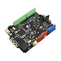
�Board Overview
Bluno M0 Mainboard (Arduino Compatible)
Num Label
Description
USB Power; Program downloading port; Serial port
1 USB COM Port
2 Power Supply
(USB COM port, Bluetooth and Hardware Serial Port 1 share the
same port: Serial)
DC 2.1 power supply port
3
Digital IO
D0~D13
Digital IO D0~D13 (Leonardo Compatible)
4
Digital IO
D24~D31
Digital IO D24~D31
5 SPI Interface
D14, D15, D16 (Pin Multiplexing)
6 Analog A0~A5
Analog A0~A5
7 MCU
NUC123LD4AN0
8 USB Serial Port USB Power; USB Serial Port(called USBSerial in code)
NOTE: Bluno M0 can be charged by USB x 2 and DC 2.
�
PinMap
Bluno M0 Pins
IC pin
Multiplex
Note
D0
D1
D2
D3
D4
D5
D6
D7
D8
D9
D10
D11
D12
D13
D14
D15
D16
D17
D18
D19
D20
D21
D22
D23
D24
D25
D26
D27
D28
D29
D30
D31
D32
PC4
PC5
PF2
PF3
PC0
PC3
PA13
PC2
PC3
PA14
PA15
PB8
PC1
PB14
PA10
PA11
PC11
PB6
PD0
PD1
PD2
PD3
PD4
PD5
PB4
PB5
PC10
PC9
PC13
PC12
PB9
PB10
PB7
RXD1
TXD1
SDA
SCL
I2S LRCLK
PWM0
PWM1
I2S DI
I2S DO
PWM2
PWM3
PWM4
I2S BCLK
PWM5
SPI MISO
SPI SCK
SPI MOSI
RX LED
A0
A1
A2
A3
A4
A5
RXD2
TXD2
NULL
NULL
NULL
NULL
NULL
NULL
TX LED
Serial-RX
Serial-TX
INT0
INT1
/
/
/
/
/
/
/
Software PWM
/
Software PWM
/
/
/
/
/
/
/
/
/
/
RX2
TX2
/
/
/
/
/
/
/
�Tutorial
Requirements
Hardware
Bluno M0 x 1
Micro USB Cable x1
Software
Arduino IDE (Version requirements: V1.6.X and later), Click to Download Arduino IDE from Arduino®
https://www.arduino.cc/en/Main/Software
Setup Bluno M0 Software Development Environment
Open Arduino IDE, File->Preferences, find Additional Boards Manager URLs, copy the below
link, and paste in the blank.
https://raw.githubusercontent.com/DFRobot/DFRobotDuinoBoard/master/package_dfrobot_m3_i
ndex.json
File->Preferences
�
paste url here
Click OK
Open Tools->Board->Boards Manager, enter Bluno in the search box, click Install
Found “Bluno M0”
�Install Bluno M0 MainBoard
Now, the development environment has been installed, you can use it like a normal Arduino
board.
�Driver Installation
Some Win10 systems will install driver automatically. Please open device manager to check
whether the COM X is installed, if yes, you can just download the program.
Connect M0 to your computer, and you will find an unknown device in the device manager.
Update Driver Software --> Browse my computer for driver software .
Generally, this driver is located in the SDK folder
C:\Users\yourUserName\AppData\Local\Arduino15\packages\nucDuino\hardware\nucDuin
o\1.0.0\driver
Or you can download it here directly: Click to save. Sometime you need disable the digital
signature.
Bluetooth Instruction
Bluno M0 is consistent with Bluno series in Bluetooth. Please refers to Bluno SKU:DFR0267 for
details.
Special Function
Hardware Serial port x2 & USB Serial Port x1
Just like Arduino Leonardo, M0 has USB Serial Port and Hardware Serial Port. No like
DFRduino M0, Bluno don't have Serial1. USB COM port, Bluetooth and Hardware Serial Port 1
share the same port: Serial.
�
USB Serial Port
Serial
Hardware Serial Port 1
Serial
Hardware Serial Port 2
Serial2
Sample Code1: D0&D1 refers to Serial, serial2 refers to Serial2. Users can use USB serial
transformer tools to check printing.
void setup() {
// put your setup code here, to run once:
Serial.begin(115200);
Serial2.begin(115200);
}
void loop() {
// put your main code here, to run repeatedly:
Serial.println("I am Serial");
Serial2.println("I am Serial 2");
delay(1000);
}
Result1: Use USB serial transforming board to receive data from Serial2 and you can check
printing in correspond in PC.
Sample Code2: Digital IO
int pin;
void setup() {
// put your setup code here, to run once:
for(pin=24;pin