SKU:KIT0150
Get Started with Respberry Pi
Learning Objectives
•
Get to know Raspberry Pi
Learning Contents
Introduction
What is Raspberry Pi?
The Raspberry Pi is a low cost, credit-card sized computer that plugs into a computer monitor or
TV, and uses a standard keyboard and mouse. It is a capable little device that enables people of
all ages to explore computing, and to learn how to program in languages like Scratch and Python.
It’s capable of doing everything you’d expect a desktop computer to do, from browsing the
internet and playing high-definition video, to making spreadsheets, word-processing, and playing
games. With the release of Windows 10 IoT, We will also be able to use the Raspberry Pi to run
Windows.
Raspberry Pi was developed by the Raspberry Pi Foundation, a UK charity, with Eben·Upton in
Cambridge University as the project leader. In March 2012, he officially released the world’s
smallest desktop computer, also known as a card computer, which is only the size of a credit card
but has all the basic functions of a computer. This is the Raspberry Pi computer board. The
foundation aims to improve the education of computer science and related subjects in schools to
make computers interesting. And it expects that this computer will continue to be developed and
applied to more fields, whether in developing or developed countries. In 2006, the early concept
of Raspberry Pi was based on Atmel's ATmega644 microcontroller. The first batch of 10,000
sets of Raspberry Pi boards were made by manufacturers in Taiwan and mainland China.
It is an ARM-based microcomputer motherboard with SD/MicroSD card as the memory hard
disk. There are 1/2/4 USB ports and a 10/100 Ethernet port around the card motherboard (A type
has no network port), which can be connected to a Keyboard, mouse, and network cable, as well
as a TV output interface for video analog signals and an HDMI high-definition video output
�interface. The above components are all integrated on a motherboard that is only slightly larger
than a credit card. It has all the basic functions of a PC. But the Raspberry Pi B model only
provides a computer board without memory, power supply, keyboard, case or connection.
Differences between Raspberry Pi models
Selection guide
Raspberry Pi Peripherals
�Summary
As everyone has a preliminary understanding of Raspberry Pi, now we are going to learn how to
use the 37 PCs Sensor kit on Raspberry Pi 4B.
Preparation
Hardware
•
•
•
•
•
•
•
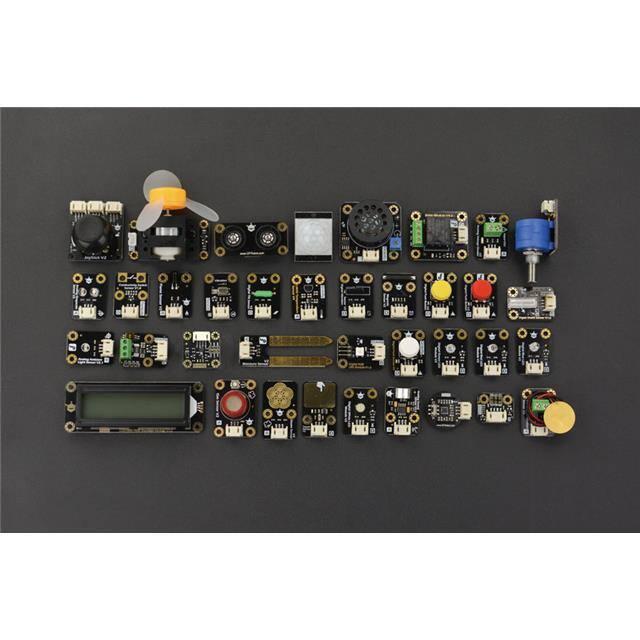
Gravity: 37 Pcs Sensor Set
Raspberry Pi 4 Model B
IO Expansion HAT for Raspberry Pi 4B/3B+
8GB + SanDisk Class10 SD/MicroSD Memory Card
5V@3A USB Power Supply
8.9 IPS Touch Display
Card Reader
Install Raspberry Pi System
�It is recommended to use a SanDisk Class10 SD card with memory storage of 8G and above. The
SD card purchased online may already have image burned inside. However, as system is
constantly updating and there are so many systems for Raspberry Pi now (you can't play them
all), so burning OS by yourself is a necessary skill. Now we will take the Raspbian system as an
example.
Download the Latest Disc Image
•
•
Enter Raspberry Pi official web: http://www.raspberrypi.org/downloads/
Find the latest Imager to download.
It is recommended to download Raspberry Pi OS (32-bit) with desktop and recommended
software.
Burn to write raspbian image to SD Card on Windows
•
Download Win32DiskImager: Baidu Cloud Link(https://pan.baidu.com/s/1i3oY1Hr)
It will be installed like this:
•
Insert your SD card and remember the drive letter
�•
Open the burning software above
•
Select the disc images downloaded before and the corresponding drive letter. Be careful not to
get it wrong. And then you can go ahead and “WRITE”
•
If it can't operate properly, format the SD card and try again
After doing this, remove the SD card from your computer and insert it into the Raspberry Pi,
then it’s ready to use now.
•
First Time Booting Up
•
Connect the Raspberry Pi to the screen as shown in the picture below
�•
•
Insert the Raspberry Pi expansion board and the burned SD card into the Raspberry Pi. Then
power it on.
Press ‘Next’ to setup your Raspberry Pi
�•
Select your location and press ‘Next’.
•
Set password (If not set, ‘raspberry’ will be default password). Then press ‘Next’.
•
Select this according to your needs and press ‘Next’ to save your setting.
�•
Select your WIFI network and press ‘Next’ to enter your password, or press ‘Skip’ to skip this
step.
•
Press ‘Skip’ or ‘Next’ according to your needs.
•
Press ‘Restart’ to restart your Raspberry Pi
�•
Enable interfaces of Raspberry Pi such as I2C, SPI, GPIO, serial port, etc. Press ‘OK’ to restart it
(Ignore if they are already enabled).
•
Install Python dependency libraries and git, and you need to get your Raspberry Pi connect to
internet for this step(skip if installed). In the terminal, type the following commands and press
‘Enter’
sudo apt-get install build-essential python-dev python-smbus git
•
Update WiringPi Library. In the terminal, type the following instructions in order and press
‘Enter’
cd /tmp
wget https://project-downloads.drogon.net/wiringpi-latest.deb //Down load wiringpi
library
sudo dpkg -i wiringpi-latest.deb //Install wiringpi Library
gpio readall //Read GPIO code number
�•
All preparations are completed now.
Lesson 1: Digital LED Light Emitting Module
Learning Goals
Let’s start our Raspberry Pi journey from lighting up an LED!
In terms of hardware, you'll learn about Raspberry Pi LED and GPIO output, which is important
for later projects. In this process, you'll also come into contact with Python programming and
you may find that programming isn't as complicated as you think.
Now let's use Raspberry Pi to control a digital LED light emitting module in this basic project.
Learning Contents - LED Flicker
Guide: In the first project, we will learn about the following contents:
�1. Internal circuit resolution of digital LED light emitting module
2. Basic uses of Thonny Python IDE
3. Basic Python code for operating GPIO.
Hardware
•
•
•
•
•
•
Gravity: 37 Pcs Sensor Set
Raspberry Pi 4 Model B
IO Expansion HAT for Raspberry Pi 4B/3B+
8GB + SanDisk Class10 SD/MicroSD Memory Card
5V@3A USB Power Supply
8.9 IPS Touch Display
Connection
•
Connect the necessary peripherals such as the screen, power, keyboard and mouse to your
Raspberry Pi.
•
Install the IO expansion board on the Raspberry Pi. And connect the LED light-emitting module
to the digital port 12 of the expansion board. Then start it up.
�•
By analyzing the LED light-emitting module circuit, we can see that the signal pin is directly
connected to the base of an NPN transistor, whose collector and emitter are respectively
connected to the negative electrode of the LED and the negative electrode of the power supply,
and the positive electrode of the LED is connected to a current-limiting resistor and then
connects to VCC. That is to say, when the signal pin appears at a high level, the collector and
emitter of the transistor are connected, then the circuit forms a loop, lightening up the LED.
When the signal pin is in low level, the LED will be off.
•
Open Thonny Python IDE to copy the following program into it
�Code
import RPi.GPIO as GPIO
# Import the python module provided by the Raspberry Pi
import time
# Import time package to control flicker
LED=12
# Define the pin number to which the LED is connected
GPIO.setmode(GPIO.BCM)
# Set GPIO mode, BCM mode is
all Raspberry Pi
GPIO.setup(LED,GPIO.OUT)
# Set GPIO12 to output mode
while True:
# Execute the following commands
GPIO.output(LED,GPIO.HIGH)
# Set the LED signal pin
LED)
time.sleep(1)
# Delay one second
GPIO.output(LED,GPIO.LOW)
# Set the LED signal pin
LED)
time.sleep(1)
# Delay one second
•
Click ‘Save’ to set the file name and the path you like to save
universally available to
in an infinite loop
high (i.e. turn on the
low (i.e. turn off the
�•
Click ‘Run’, then you can see the LED is flickering
Lesson 2: Digital Push Button Module
Learning Goals
In the last tutorial, we have learned how to simply control the on and off of the LED module. In
this tutorial, we will learn about Raspberry Pi buttons and GPIO inputs based on the previous
tutorial, which is very important for future projects. In this process, you will be exposed to new
Python programs.
Learning Contents – Control LED by the Button
Guide: In this project, we will learn the basic principles of the button module. And we will also
consolidate the basic uses of Thonny Python IDE we learned before, as well as the basic Python
code for operating GPIO.
�Hardware
•
•
•
•
•
•
Gravity: 37 Pcs Sensor Set
Raspberry Pi 4 Model B
IO Expansion HAT for Raspberry Pi 4B/3B+
8GB + SanDisk Class10 SD/MicroSD Memory Card
5V@3A USB Power Supply
8.9 IPS Touch Display
Connection
•
Connect the necessary peripherals such as the screen, power, keyboard and mouse to your
Raspberry Pi.
•
Install the Raspberry Pi IO expansion board on your ‘Pi’ and connect the LED light-emitting
module to digital port 12 on the expansion board, and the digital push button module to the
digital port 8. Then power on.
�•
By analyzing the schematic circuit diagram of this module, we can see that when release the
button, the signal output pin is at low level and the indicator light is off. When the button is
pressed, the signal pin is at high level and the indicator light is on. They are corresponding to the
two states of the LED light-emitting module. In this case, the button can be used to control the
LED light through a simple judgment by the Raspberry Pi.
•
Open Thonny Python IDE to copy the following program into it
�Code
import RPi.GPIO as GPIO
# Import the python module provided by the Raspberry Pi
import time
# Import time package to control flicker
LED=12
Blue=8
# Define the pin number to which the LED is connected
# Define the pin number to which the button is connected
GPIO.setmode(GPIO.BCM)
Raspberry Pi
GPIO.setup(LED,GPIO.OUT)
GPIO.setup(Blue,GPIO.IN)
# Set GPIO mode, BCM mode is universally available to all
# Set GPIO12 to output mode
#Set GPIO8 to input mode
while True:
# Execute the following commands in an infinite loop
if GPIO.input(Blue): # GPIO.input(Blue) will return to the state of GPIO8 and
judge it. If GPIO8 is high (that is, the button is pressed), execute the following
statement
GPIO.output(LED,GPIO.HIGH)
# Set the LED signal pin high (i.e. light up
the LED)
else :
# If GPIO8 is low (that is, the button is released), execute the
following statement
GPIO.output(LED,GPIO.LOW)
# Set the LED signal pin low (i.e. turn off the
LED)
time.sleep(0.1)
# Delay one second, here is to control the frequency for querying
key status
•
Click ‘Save’ to set the file name and the save path you like
�•
Click ‘Run’, you can see that the light is on and off with the button pressed and released.
�Lesson 3: LM35 Analog Linear Temperature Sensor
Learning Contents
Introduction to LM35 Analog Linear Temperature Sensor
Based on LM35 semiconductor, this sensor produced by National Semiconductor Corporation
can be used to detect ambient temperature. It offers a measurement range from -40 °C to 150
°C and a sensitivity of 10 mV/°C. And its output voltage is proportional to the temperature.
Moreover, if used in combination with sensor-specific expansion of Arduino board, this sensor
can be really easy to achieve interactive effects related to ambient temperature perception.
Commonly-used sensors for temperature measurement include thermocouples, platinum
resistance, thermal resistance and temperature semiconductor chips. Thermocouples are
commonly used in high temperature measurement. Platinum resistance temperature modules are
used in measurement of 800 degrees Celsius, while the thermal resistance and semiconductor
temperature sensor are suitable for measuring the temperature of 100-200 degrees or below. With
good linearity and high sensitivity, the semiconductor temperature sensor is easy to use.
Precautions
The port layout of the new analog sensor has the following two improvements. Please refer to the
blog How to change the layout of the data cable connector. When using this sensor on the IO
expansion board, you may need to adjust the layout of the connector. For your convenience, we
will make more improvements, so stay tuned.
�Use LM35 Analog Linear Temperature Sensor on Your Raspberry Pi
•
Connect the sensor to the analog pin 0 on the expansion board
•
Open Thonny Python IDE to copy the following program into it
Lesson 4: I2C Digital Wattmeter
Introduction
I2C Digital Wattmeter is a high-resolution, high-precision, large-scale measurement module that
can measure the voltage, current and power of various electronic modules and electrical
equipment within 26V 8A, and the maximum relative error is no more than ±0.2% (A simple
manual calibration is required before using). It can be used for power consumption measurement
or battery life evaluation of solar energy systems, battery coulombmeters, motors, controllers or
electronic modules.
This module adopts TI INA219 zero temperature drift current/power monitoring chip and 2W
high power low temperature drift 10mΩ alloy sampling resistor. The voltage and current
resolution can reach 4mV and 1mA respectively. Under the full-scale measurement condition,
�the maximum relative error of voltage and current measurement can be superior to ±0.2%. It also
provides four I2C addresses that can be configured via the 2P DIP switch. The module accurately
measures bi-directional high-side currents (current flowing through the power supply or battery
positive), which is especially useful in solar or battery fuel gauge applications where the battery
needs to be charged and discharged. This status can be simply determined by positive or negative
current readings. In the motor applications, the current can be monitored in real time by
monitoring whether the motor current is too large due to overload. In addition, you can use this
module to measure the power consumption of various electronic modules or the entire project to
evaluate battery life.
Use I2C Digital Wattmeter on Your Raspberry Pi
•
•
•
Power the Raspberry Pi on and install the Raspberry Pi expansion board correctly
Connect the sensor to the IIC interface on the expansion board
Configure to enable I2C and restart the Raspberry Pi. If configured, you can skip this step.
Configure the Raspberry Pi according to the following procedure and restart it.
�•
Install I2C libraries and tools, and you need to get your Raspberry Pi connect to internet for this
step(skip if installed). In the terminal, type the following instructions and press ‘Enter’
sudo apt-get install i2c-tools
•
When the I2C device is connected, the I2C address can be checked by the following command.
In the terminal, type the following instructions and press ‘Enter’
sudo i2cdetect -y -a 1
•
Read all register data of I2C device. In the terminal, type the following instructions and press
‘Enter’
�sudo i2cdump -y 1 0x45
-y means cancelling the user interaction process and directly executing the command 1 is the I2C
device number 0×45 is I2C device address
•
Install Python dependency libraries and git, and you need to get your Raspberry Pi
connect to internet for this step(skip if installed). In the terminal, type the following
instructions and press ‘Enter’
sudo apt-get install build-essential python-dev python-smbus git
•
Install the drive library. In the terminal, type the following instructions in order and press
‘Enter’
cd \~
git clone https://github.com/DFRobotdl/37\_Pcs\_Sensor.git
•
Find get_voltage_current_power.py in 37_Pcs_Sensor\4_I2C_Digital_Wattmeter, open it
with Thonny Pyth IDE and run it, then you can see the printed data.
�•
Click ‘run’, it will show current, voltage, and other information.
Lesson 5: TCS34725 I2C Color Sensor
Learning Contents
Lead-in
Want to know the secret to chameleons’ ability to change color? Want know how the most
popular electronic color picking pen picks color? Don't think too complicated, because their
principle is really simple. Nature, is the best teacher of mankind. There are so many interesting
ideas inspired by creatures.
Through tens of millions of years of derivation, the chameleon has formed a biological instinct,
which can be perfectly hidden in the surroundings by changing the protective color of its skin.
This is a process from "color picking" to "color matching".
Today, electronic color picking pens use the same principle. First, obtain the RGB three primary
color values by detecting the color of the object. Then blend these values to get the color of the
object. It's just like kneading plasticine when you were a kid. After knowing a certain ratio, you
can knead the color you want.
�Introduction to I2C Color Sensor
TCS34725 is a low-cost and cost-effective RGB full-color sensor. The sensor recognizes the
surface color of an object through optical sensing. It supports the three primary colors of red,
green, and blue (RGB), supports bright light sensing, and can output the corresponding specific
values to help restore the true colors.
For a higher precision, it specifically employs a IR blocking filter at bottom to avoid interference
from the surroundings, minimizing the infrared spectrum component of the incident light. In this
case, it gets a more accurate color management. Besides, this sensor also includes four ultrabright LEDs to allow itself to work without external light resources. And the module works via
I2C bus, featuring PH2.0-4P and XH2.54 (breadboard) interfaces to meet different using
requirements.
Use I2C Color Sensor on Your Raspberry Pi
•
•
•
Power the Raspberry Pi on and install the Raspberry Pi expansion board correctly
Connect the sensor to corresponding IIC interface on the expansion board
Configure to enable I2C and restart the Raspberry Pi. If configured, you can skip this step.
Configure the Raspberry Pi according to the following procedure and restart it.
�•
Install I2C libraries and tools, and you need to get your Raspberry Pi connect to internet for this
step(skip if installed). In the terminal, type the following instructions and press ‘Enter’
sudo apt-get install i2c-tools
•
When the I2C device is connected, the I2C address can be checked by the following command.
In the terminal, type the following instructions and press ‘Enter’ sudo i2cdetect -y -a 1
•
Read all register data of I2C device. In the terminal, type the following instructions and
press ‘Enter’ sudo i2cdump -y 1 0x29
•
y means cancelling the user interaction process and directly executing the command 1 is
the I2C device number 0×29 is I2C device address
�•
Open Thonny Python IDE to copy the following program into it
import smbus
import time
bus = smbus.SMBus(1)
addr = 0x29
CDATAL
CDATAH
RDATAL
RDATAH
GDATAL
GDATAH
BDATAL
BDATAH
=
=
=
=
=
=
=
=
0x94
0x95
0x96
0x97
0x98
0x99
0x9a
0x9b
while True:
ClearL = bus.read_byte_data(addr , CDATAL)
ClearH = bus.read_byte_data(addr , CDATAH)
Clear = ClearH * 0x100 + ClearL
print("Clear = 0X%x" %Clear)
RedL = bus.read_byte_data(addr , RDATAL)
RedH = bus.read_byte_data(addr , RDATAH)
Red = RedH * 0x100 + RedL
print("Red
= 0X%x" %Red)
GreenL = bus.read_byte_data(addr , GDATAL)
GreenH = bus.read_byte_data(addr , GDATAH)
Green = GreenH * 0x100 + GreenL
print("Green = 0X%x" %Green)
BlueL = bus.read_byte_data(addr , BDATAL)
BlueH = bus.read_byte_data(addr , BDATAH)
Blue = BlueH * 0x100 + BlueL
print("Blue = 0X%x" %Blue)
print("
")
time.sleep(1)
�•
Click ‘Run’, it will print the color information.
Lesson 6: Analog Rotation Sensor
Learning Contents
Introduction to Analog Rotation Sensor V2
As the rotation angle of the ordinary potentiometer is only 300 degrees at most, the accuracy is
quite low after distributing the 5V power supply of Arduino to every 1 degree.
So if you want to make a project with precise control of angle or analog quantity, this precision
angle sensor is a good choice. Based on a multi-turn precision potentiometer, this sensor can be
rotated about 10 turns and subdivide the voltage into 1024 parts. What’s more, it can be
combined with the sensor expansion board through the 3P connection line, accurately sensing
small changes in rotation.
*This product has been updated. Please refer to the product wiki at the bottom of the page for the
specific line sequence of the V2 version. For V1 version, please connect according to the "1, 2,
3" marked on the module's silk screen.
Use Analog Rotation Sensor on Your Raspberry Pi
•
Power the Raspberry Pi on and install the Raspberry Pi expansion board correctly
•
Connect the sensor to the analog port 0 on the expansion board
�•
Install Python dependency libraries and git, and you need to get your Raspberry Pi connect to
internet for this step(skip if installed). In the terminal, type the following instructions and press
‘Enter’
sudo apt-get install build-essential python-dev python-smbus git
• Install the drive library and program. In the terminal, type the following instructions
press ‘Enter’ cd \~
git clone https://github.com/DFRobotdl/37\_Pcs\_Sensor.git
•
and
Find Analog_Rotation_Potentiometer_Sensor_V2.py in
37_Pcs_Sensor\6_Analog_Rotation_Potentiometer_Sensor, open it with Thonny Pyth
IDE and run it, you can see the printed analog value, which will change if you rotate the
sensor.
�Lesson 7: 130 DC Motor Fan
Learning Contents
Introduction
This module is really interesting. It can be easily driven by Arduino without an additional motor
driver board. You can also use the PWM pulse width to adjust its speed, which is suitable for
light applications or small DIY. Simple, but useful.
Use 130 DC Motor Fan on Your Raspberry Pi
•
Power the Raspberry Pi on and install the Raspberry Pi expansion board correctly
•
Connect the fan to PWM port 0 on the expansion board, and the analog rotation sensor to
analog port 0
�•
Install Python dependency libraries and git, and you need to get your Raspberry Pi
connect to internet for this step(skip if installed). In the terminal, type the following
instructions and press ‘Enter’ sudo apt-get install build-essential python-dev
python-smbus git
•
Install the drive library and program. In the terminal, type the following instructions in
order and press ‘Enter’ cd \~
git clone https://github.com/DFRobotdl/37\_Pcs\_Sensor.git
•
Find 130_DC_Motor_Module.py in \37_Pcs_Sensor\7_130_DC_Motor_Module folder,
open it with Thonny Pyth IDE and run it, the fan speed can be adjusted through the
rotation sensor.
�Lesson 8: JoyStick
Learning Contents
Introduction to JoyStick
The JoyStick produced by DFRobot is made with original high-quality metal PS2 rocker
potentiometer. With (X, Y) 2 axis analog output and (Z) 1 button digital output, it can maintain
good contact and mechanical properties no matter how you torture it. The 3 signals are
respectively connected to the Arduino sensor expansion board through the 3P line, occupying
only 3 ports for its control.
Features of its new version:
•
•
•
•
•
Operating Voltage: 3.3 V/5 V, suitable for more 3.3 V controllers.
Standard Size: The distance between two mounting holes with a diameter of 3mm is several
times that of 5mm
Easy to Identify: The two analog output interfaces are marked with S, while the digital interface
is marked with D
High-quality connectors, resistant to repeated plugging and unplugging
Immersion gold technology, not only improving the quality of PCB board, but also being with
golden fonts.
Precautions
The layout of the new version of the analog sensor port has the following two improvements.
Please refer to the blog How to change the layout of the data cable connector. When using
this sensor on the IO expansion board, you may need to adjust the layout of the connector. For
your convenience, we will make more improvements, so stay tuned.
�Use JoyStick on Your Raspberry Pi
•
Power the Raspberry Pi on and install the Raspberry Pi expansion board correctly
•
Connect the X-axis output port of the JoyStick to the analog port 0 on the expansion
board, the Y-axis output port to the analog port 1, and the Z-axis output to the digital port
8
•
Install Python dependency libraries and git, and you need to get your Raspberry Pi
connect to internet for this step(skip if installed). In the terminal, type the following
instructions and press ‘Enter’ sudo apt-get install build-essential python-dev
python-smbus git
•
Download drive library and program. In the terminal, type the following instructions and
press ‘Enter’ cd \~
git clone https://github.com/DFRobotdl/37\_Pcs\_Sensor.git
•
Find 7_Joystick_Module_V2.py in \37_Pcs_Sensor\8_Joystick_Module_V2, open and
run it with Thonny Pyth IDE, you can see the printed X, Y, Z axis data. The value will
change if you flip or press the joystick.
�Lesson 9: Analog Light Sensor
Learning Contents
Introduction
Based on PT550 environmentally friendly photodiode, this light sensor can be used to detect the
intensity of ambient light. It is usually used to produce interactive works that produce special
effects with changes in light intensity. The entire module is connected to the IO expansion board
with a 3P analog data cable. As long as the color is corresponding, it will not be inserted wrong,
really convenient.
•
•
Wider Operating Voltage: 3.3 V~5 V
Standard fixing hole design, two 3mm fixing holes separated by 5cm.
�This LCD screen can display the detected light intensity of the sensor, which is reflected by the
size of the circle
Precautions
The layout of the new version of the analog sensor port has the following two improvements.
Please refer to our blog "How to change the data line connector layout" instructions. When using
the sensor on the IO expansion board, you may need to adjust the layout of the connector. For
your convenience, we will make more improvements, so stay tuned.
�Use Analog Light Sensor on Your Raspberry Pi
•
•
•
Power the Raspberry Pi on and install the Raspberry Pi expansion board correctly
Connect the sensor to analog port 0 on the expansion board
Install Python dependency libraries and git, and you need to get your Raspberry Pi
connect to internet for this step(skip if installed). In the terminal, type the following
instructions and press ‘Enter’ sudo apt-get install build-essential python-dev
python-smbus git
•
Install the drive library and program. In the terminal, type the following instructions and
press ‘Enter’ cd \~
git clone https://github.com/DFRobotdl/37\_Pcs\_Sensor.git
•
Find Analog_Ambient_Light_Sensor.py in
\37_Pcs_Sensor\9_Analog_Ambient_Light_Sensor, open and run it with Thonny Python
IDE, you can see the printed corresponding value of the light
�Lesson 10: Digital Vibration Sensor
Learning Contents
Introduction
What's the simplest way to check vibration with electric devices? Use a vibration switch to turn
on and off the circuit through vibration to generate a signal. Despite a simple structure, you can
make full use of this vibration sensor with creative thinking, like step counting, Crash warning
light and so on. As long as you have ideas, the usage of simple components will change
endlessly. As long as you have ideas, the usage of simple components can be varied an infinite
number of times.
�This is a very simple pedometer that can count the number of steps you take.
Use Digital Vibration Sensor on Your Raspberry Pi
•
Connect the digital LED light-emitting module to the pin 12 on extension board, and connect the
digital vibration sensor to the pin 8.
•
Open Thonny Python IDE to copy the following program into it
import RPi.GPIO as GPIO
import time
import atexit
LED=12
Vibration=8
atexit.register(GPIO.cleanup)
GPIO.setmode(GPIO.BCM)
GPIO.setup(LED,GPIO.OUT)
GPIO.setup(Vibration,GPIO.IN)
while True:
if GPIO.input(Vibration):
GPIO.output(LED,GPIO.HIGH)
else :
GPIO.output(LED,GPIO.LOW)
time.sleep(0.1)
�•
Click ‘Run’, you can observe that when the sensor detects vibration, the LED will go out.
Lesson 11: Analog Sound Sensor
Learning Contents
Introduction
This is a simple and affordable microphone through which the Arduino can sense the level of the
sound and convert it into an analog signal. That is, the volume is reflected by the feedback
voltage value. The analog data line directly corresponds to the analog port on the IO expansion
board V7. Plug in and burn the code, you can use it.
�The sensor reads O when completely muted. When there is music nearby, it will read various
readings with the volume.
Precautions
The layout of the new version of the analog sensor port has the following two improvements.
Please refer to our blog "How to change the data line connector layout" instructions. When using
the sensor on the IO expansion board, you may need to adjust the layout of the connector. For
your convenience, we will make more improvements, so stay tuned.
Use Analog Sound Sensor on Your Raspberry Pi
•
•
Power the Raspberry Pi on and install the Raspberry Pi expansion board correctly
Connect the sensor to analog port 0 on the expansion board
�•
Install Python dependency libraries and git, and you need to get your Raspberry Pi
connect to internet for this step(skip if installed). In the terminal, type the following
instructions and press ‘Enter’ sudo apt-get install build-essential python-dev
python-smbus git
•
Download the drive library and program. In the terminal, type the following instructions
and press ‘Enter’ cd \~
git clone https://github.com/DFRobotdl/37\_Pcs\_Sensor.git
•
Find Analog_Sound_Sensor.py in \37_Pcs_Sensor\11_Analog_Sound_Sensor, open and
run it with Thonny Python IDE, you can see the printed sound values. The smaller value,
the louder volume. And vice versa.
�Lesson 12: Heart Rate Monitor Sensor
Learning Contents
Introduction
The DFRobot heart rate sensor, despite a tiny size of just a thumb, can monitor human heart
rates. Compatible with Arduino main controllers, this plug-and-play module is really convenient
to use that it’s equipped with Gravity 3-Pin interface. It uses PPG (Photo Plethysmo Graphy) to
measure heart rate, a low-cost optical technology that monitors the human heart rate by detecting
blood oxygen levels in subcutaneous capillaries. Besides, this technology features fast response,
stable performance and strong adaptability. As being equipped with two mounting holes, the
sensor can be wrapped on your finger, wrist, earlobe or other areas where it has contact with
your skin.
�The module has two signal output modes: square wave and pulse wave, which can be freely
switched through the on-board switch. The pulse wave outputs a continuous heart rate waveform,
while the square wave outputs a corresponding square wave according to heart rates.
Precautions
1. This is a static heart rate sensor. Please do not move or press too tightly during its
measurement.
2. This product is NOT a professional medical device and should not be used to diagnose or treat
medical conditions.
Use Heart Rate Sensor on Your Raspberry Pi
•
Connect the digital LED light-emitting module to the pin 12 on extension board, the heart rate
sensor to the pin 8, and the analog light sensor to the analog port 0.
•
Open Thonny Python IDE and copy the following program into it.
�import RPi.GPIO as GPIO
import time
import atexit
LED=12
Heart_Rate=8
atexit.register(GPIO.cleanup)
GPIO.setmode(GPIO.BCM)
GPIO.setup(LED,GPIO.OUT)
GPIO.setup(Heart_Rate,GPIO.IN)
while True:
if GPIO.input(Heart_Rate):
GPIO.output(LED,GPIO.HIGH)
else :
GPIO.output(LED,GPIO.LOW)
time.sleep(0.1)
•
Then the LED will go on and off with your heartbeat.
�Lesson 13 Conductivity Sensor Switch
Preface
Lead-in
In this section we will introduce the conductivity switch sensor. We can use it to test the
conductivity of the object, and can also use it as a switching device for special occasions.
Introduction
The conductivity switch is to conduct through two exposed conductors. When the two sides are
connected through a certain medium, they are turned on. And the sensor can detect whether there
is an object connection between the two poles. When the resistance value of the connected object
is less than 10M, it can output a high level. You can use it to make a fruit piano, music wind
chime, handshake sensor light and other interesting applications.
Hardware
•
•
•
•
•
•
Gravity: 37 Pcs Sensor Set
Raspberry Pi 4 Model B
IO Expansion HAT for Raspberry Pi 4B/3B+
8GB + SanDisk Class10 SD/MicroSD Memory Card
5V@3A USB Power Supply
8.9 IPS Touch Display
Learning Contents
Connection
•
Connect the Raspberry Pi correctly to devices such as the screen, power, keyboard and mouse.
�•
Install the Raspberry Pi IO expansion board on the Raspberry Pi and connect the LED light
module to the No. 12 digital port on the board, and the conductivity switch sensor module to
the No. 8 digital port. When we touch to connect the two alligator clips with our hands or other
conductive objects, we can see the corresponding phenomenon.
•
Expansion Board Connection
�Operating Principle
Change the level signal as a switch by conducting two metal sheets.
Schematic
�Software
•
Open Thonny Python IDE to copy the following program into it
import RPi.GPIO as GPIO
# Import the python module provided by the Raspberry Pi
import time
# Import time package to control flicker
LED=12
# Define the pin number to which the LED is connected
Electrical_switch = 8
# Define the pin number to which the
switch is connected
GPIO.setmode(GPIO.BCM)
Raspberry Pi
GPIO.setup(Electrical_switch,GPIO.IN)
GPIO.setup(LED,GPIO.OUT)
GPIO.output(LED,GPIO.HIGH)
# Set GPIO mode, BCM mode is common to all
# Set GPIO12 to output mode
# Set GPIO8 to input mode
#Define LED original value
while True:
# Execute the following commands in an
infinite loop
key = GPIO.input(Electrical_switch)
if (key ):
# Judge whether the button is pressed
GPIO.output(LED,GPIO.LOW)
# Button pressed, start the micro vibrator
else :
# If GPIO8 is low (that is, the button is released),
execute the following statement
GPIO.output(LED,GPIO.HIGH)
# Not start the micro vibrator
time.sleep(0.01)
# Delay one second, here is to control the frequen
cy of the query key
�•
Click ‘Save’ after copying
•
Set the file name and the save path you like
�•
Press ‘Run’ or ‘Stop’ the program
•
After running it, check the corresponding phenomenon
http://https//www.bilibili.com/video/BV1z54y1b763/
Lesson 14: Analog Voltage Monitoring Module
Preface
Introduction
Based on the resistance divider principle, this voltage monitoring sensor can be used with the
Arduino sensor expansion board to detect the voltage and power level, monitoring the power of
interactive media works or the robot power supply.
This module can reduce the input voltage by 5 times. Since the maximum Arduino analog input
voltage is 5 V, its input voltage cannot be greater than 5 V × 5 = 25 V.
Hardware
•
•
•
•
•
•
Gravity: 37 Pcs Sensor Set
Raspberry Pi 4 Model B
IO Expansion HAT for Raspberry Pi 4B/3B+
8GB + SanDisk Class10 SD/MicroSD Memory Card
5V@3A USB Power Supply
8.9 IPS Touch Display
�Learning Contents
Connection
•
Connect the Raspberry Pi correctly to devices such as the screen, power, keyboard and mouse.
•
Connect the pin of this module to pin 0 on the Analog board of the Raspberry Pi expansion
board. The schematic diagram is as follows.
�•
Connect a power to power it on. The wiring diagram is as follows.
Program
•
Open the system to enter the terminal
�•
Install Python dependency libraries and git, and you need to get your Raspberry Pi connect to
internet for this step(skip if installed). In the terminal, type the following instructions and press
‘Enter’ sudo apt-get install build-essential python-dev python-smbus git
•
Download the drive library and program. git clone
https://github.com/DFRobotdl/111.git
•
Find DFR0051.py in the file you just downloaded before, click to run it
•
Adjust the input voltage, then the analog port will read it.
�Lesson 15: Analog Capacitive Soil Moisture Sensor
Preface
Introduction
This is a simple moisture sensor that can be used to detect soil moisture. When the soil is short of
water, its output value will decrease, otherwise it will increase. This kind of sensor is mainly
used to measure the relative water content of soil, do soil moisture monitoring, agricultural
irrigation and forestry protection.
Hardware
•
•
•
•
•
•
Gravity: 37 Pcs Sensor Set
Raspberry Pi 4 Model B
IO Expansion HAT for Raspberry Pi 4B/3B+
8GB + SanDisk Class10 SD/MicroSD Memory Card
5V@3A USB Power Supply
8.9 IPS Touch Display
Learning Contents
Connection
•
Connect the Raspberry Pi correctly to devices such as the screen, power, keyboard and mouse.
�•
Connect the sensor to analog port A0 on Raspberry Pi expansion board. The wiring diagram is as
follows.
•
Find components and connect
�Schematic and operating principle
The soil moisture sensor judges the soil moisture content by its water level.
As shown in the figure, when the soil moisture sensor probe is suspended in the air, the base of
the triode is open, and the output of the triode is 0. When it is inserted into the soil, the resistance
value of the soil is different due to the different moisture content. Then the base of the triode will
provide a variable conduction current. The conduction current from the collector to the emitter of
the triode is controlled by the base, converted into a voltage after the pull-down resistor of the
emitter.
Program
•
Install Python dependency libraries and git, and you need to get your Raspberry Pi connect to
internet for this step(skip if installed). In the terminal, type the following instructions and press
‘Enter’
sudo apt-get install build-essential python-dev python-smbus git
•
Download the drive library and program.
git clone https://github.com/DFRobotdl/111.git
•
Find SEN0114.py in the file you downloaded before, open and run it with, you can see the
printed data.
��Lesson 16: URM09 Ultrasonic Sensor
Preface
Introduction
This is an open dual-probe ultrasonic distance measurement module. Equipped with Gravity
standard PH2.0-3P vertical mount interface, it outputs analog voltage, compatible with arduino,
Raspberry Pi, and other controllers with logic level of 3.3 V or 5 V.
This module comes with temperature compensation to avoid ambient temperature from affecting
its measurements. With its analog voltage value output, it can directly read the temperature value
by ADC conversion, simplifying the operation and reducing the difficulty. Besides, this sensor
has been tested that its effective measurement range for flat walls is 2 – 500 cm, its resolution is
1cm, and the error is about ±1%. Its dual-probe greatly reduces the detection blind area. And the
on-board status indicator light is convenient to check the test progress.
Thanks to its small size, this convenient sensor that allows plug and play has strong
environmental applicability, high accuracy, wide measurement range, quite suitable for outdoor
environments, especially those with rapid temperature changes. It is also an excellent choice for
robots to avoid obstacles automatically, car reversing alarms, doorbells, warning alarms, subway
safety line prompts, bank and cash machine one-meter line prompts, and so on.
Preparation
Lead-in
URM09 ultrasonic sensor adopts analog voltage output, so we can get the corresponding test
distance through conversion. In this section, we will use Thonny Python IDE basic usage and
routine adc to do a simple ultrasonic distance measurement.
Hardware
•
•
•
•
•
•
Gravity: 37 Pcs Sensor Set
Raspberry Pi 4 Model B
IO Expansion HAT for Raspberry Pi 4B/3B+
8GB + SanDisk Class10 SD/MicroSD Memory Card
5V@3A USB Power Supply
8.9 IPS Touch Display
�Learning Contents
Connection
•
Connect the Raspberry Pi correctly to devices such as the screen, power, keyboard and mouse.
•
Connect this module to analog port A0 on Raspberry Pi expansion board.
�•
Find this position to connect the sensor correctly.
When we move the ultrasonic sensor, we can receive feedback to detect different distance
values
Software
•
Install Python dependency libraries and git, and you need to get your Raspberry Pi connect to
internet for this step(skip if installed). In the terminal, type the following instructions and press
‘Enter’
sudo apt-get install build-essential python-dev python-smbus git
•
Install the drive library and program.
git clone https://github.com/DFRobotdl/111.git
•
Find SEN0307.py in the file below, open and run it.
�•
Get result.
Lesson 17: Digital Touch Sensor
Preface
Introduction
This is a touch switch module based on capacitive sensing that can sense the direct contact of the
human body or metal on its metal surface. In addition to the direct touch, the contact with a
certain thickness of plastic, glass and other materials can also be sensed. And its sensitivity
depends on the size of the contact surface and the thickness of the covering material.
Preparation
Lead-in
We are already clear about the control of Led. Now we are going to use Thonny Python IDE and
the basic Python code operating GPIO to control Led by this digital analog sensors.
Hardware
•
•
•
•
•
•
Gravity: 37 Pcs Sensor Set
Raspberry Pi 4 Model B
IO Expansion HAT for Raspberry Pi 4B/3B+
8GB + SanDisk Class10 SD/MicroSD Memory Card
5V@3A USB Power Supply
8.9 IPS Touch Display
Learning Contents - Control LED with Digital Touch Sensor
�Connection
•
Connect the Raspberry Pi correctly to devices such as the screen, power, keyboard and mouse.
•
Install the Raspberry Pi IO expansion board on the Raspberry Pi, connect the LED light-emitting
module digital port 12 on the board, and the digital analog sensor to port 8, then turn on the Pi.
*If there is a metal object or a finger touches the metal piece, pin 8 inputs a high level and
triggers a high level on the pin 12, and the LED is on. When there is no metal object or finger
touch, the pin 12 is low and the LED is off. *
Programm
•
Open Thonny Python IDE to copy the following program into it
�import RPi.GPIO as GPIO
# Import the python module provided by the Raspberry Pi
import time
# Import time package for touch time detection
LED=12
KEY=8
# Define the pin number to which the LED is connected
# Define the pin number to which the sensor is connected
GPIO.setmode(GPIO.BCM)
GPIO.setup(LED,GPIO.OUT)
GPIO.setup(KEY,GPIO.IN)
# Set GPIO mode, BCM mode is common to all Raspberry Pi
# Set GPIO12 to output mode
# Set GPIO8 to input mode
while True:
# Execute the following commands in an infinite loop
if GPIO.input(KEY):
# GPIO.input(KEY)will return the state of GPIO and
judge, if GPIO8 is high (i.e. The sensor received signal)
GPIO.output(LED,GPIO.HIGH)
#Set LED signal pin high (Light LED on)
else :
# If GPIO8 is low (Not receive signal)
GPIO.output(LED,GPIO.LOW)
#Set LED signal pin low (Turn LED off)
time.sleep(0.1)
# Delay one second, here is to control the frequency of the query
key
�Lesson 18: Digital Steel Ball Inclination Sensor
Preface
Introduction
This is a digital module based on a steel ball switch. It utilizes the characteristics of the steel ball
to roll it towards the bottom through gravity, thereby closing or opening the switch. So it can
also be used as a simple tilt sensor.
This module can also be used in combination with the Raspberry Pi sensor expansion board. In
this case, it can be used to make very interesting interactive works, which is safer than using a
mercury switch.
�Operating Principle
It utilizes the characteristics of the steel ball to roll it towards the bottom through gravity, thereby
closing or opening the switch.
Requirements
Hardware
•
•
•
•
•
•
Gravity: 37 Pcs Sensor Set
Raspberry Pi 4 Model B
IO Expansion HAT for Raspberry Pi 4B/3B+
8GB + SanDisk Class10 SD/MicroSD Memory Card
5V@3A USB Power Supply
8.9 IPS Touch Display
Learning Contents
Connection
•
Connect the Raspberry Pi correctly to devices such as the screen, power, keyboard and mouse.
�•
Connect this sensor to pin 8 on the expansion board. For convenience, connect a led switch to
pin 12.
�Program
•
Open Thonny Python IDE to copy the following program into it
import RPi.GPIO as GPIO
import time
LED = 12
dip_key = 8
GPIO.setmode(GPIO.BCM)
GPIO.setup(LED,GPIO.OUT)
GPIO.setup(dip_key,GPIO.IN)
while True:
if GPIO.input(dip_key):
GPIO.output(LED,GPIO.HIGH)
else:
GPIO.output(LED,GPIO.LOW)
time.sleep(0.1)
�Lesson 19: Digital SMD Magnetic Induction Sensor
Preface
Introduction
This is a magnetic sensor based on high-quality reed tube that can sense the magnetic force
within 3cm (the detection distance varies with the magnitude of the magnetic force). With our IO
sensor expansion board V7, it can quickly build magnetic interaction projects.
The reed switch is disconnected in an environment without a magnetic field. When the magnetic
force is strong enough, the reeds can be contacted and conducted. This process is very fast,
making it a highly efficient and reliable switching element.
�Requirements
Hardware
•
•
•
•
•
•
Gravity: 37 Pcs Sensor Set
Raspberry Pi 4 Model B
IO Expansion HAT for Raspberry Pi 4B/3B+
8GB + SanDisk Class10 SD/MicroSD Memory Card
5V@3A USB Power Supply
8.9 IPS Touch Display
Learning Contents
Connection
•
Connect the Raspberry Pi correctly to devices such as the screen, power, keyboard and mouse.
•
Connect the LED to pin 12 on the expansion board, and the sensor to pin 8.
�Program
•
Open Thonny Python IDE to copy the following program into it
import RPi.GPIO as GPIO
#Import the python module provided by the Raspberry Pi
import time
#Import time package to detect induction time
LED = 12
magnetic_key = 8
#Define the pin number to which the LED is connected
#Define the pin number to which the sensor is connected
GPIO.setmode(GPIO.BCM)
#Set GPIO mode, BCM mode is common to all Raspberry Pi
GPIO.setup(LED,GPIO.OUT)
#Set GPIO12 to output mode
GPIO.setup(magnetic_key ,GPIO.IN)
#设Set GPIO8 to input mode
while True:
#Execute the following commands in an infinite loop
if GPIO.input(magnetic_key ):
#GPIO.input(magnetic_key )
GPIO.output(LED,GPIO.HIGH)
#Set the LED signal high (Turn off LED)
else :
#If GPIO8 is low (The sensor didn't reiceive signal)
GPIO.output(LED,GPIO.LOW)
#Set LED signal low (Turn on LED)
time.sleep(0.1)
#Delay one second, here is to control the frequency of the query ke
y
��Lesson 20: Mini Vibration Module
Preface
Lead-in
We have already introduced the digital push button module. Now let's use the module and the
miniature vibration module to control its vibration to make a simple project.
Introduction
The vibration module uses a vibration motor as the excitation source. The motor is equipped with
a set of adjustable eccentric blocks at one end of the rotor shaft, and the excitation force is
obtained by the centrifugal force generated by the high-speed rotation of the shaft and the
eccentric block.
Requirements
Hardware
•
•
•
•
•
•
Gravity: 37 Pcs Sensor Set
Raspberry Pi 4 Model B
IO Expansion HAT for Raspberry Pi 4B/3B+
8GB + SanDisk Class10 SD/MicroSD Memory Card
5V@3A USB Power Supply
8.9 IPS Touch Display
Learning Contents
Connection
•
Connect the Raspberry Pi correctly to devices such as the screen, power, keyboard and mouse.
�•
Connect the IO expansion board with the Raspberry Pi. Connect the push button module to
digital port 18, the vibration module to digital port 8.
�Schematic
Original Layout
�Program
•
Open Thonny Python IDE to copy the following program into it
import RPi.GPIO as GPIO
by the Raspberry Pi
import time
flicker
# Import the python module provided
button = 12
button is connected
vibration = 8
vibration is connected
#Define the pin number to which the
#Import time package to control
#Define the pin number to which the
GPIO.setmode(GPIO.BCM)
#Set GPIO mode, BCM mode is common to all
Raspberry Pi
GPIO.setup(button,GPIO.IN)
#Set GPIO12 to input mode
GPIO.setup(vibration,GPIO.OUT)
# Set GPIO8 to output mode
while True:
# Set GPIO8 to input mode
key = GPIO.input(button)
if (key ):
#Judge whether the button is pressed
GPIO.output(vibration,GPIO.HIGH)
#Button pressed, start the micro
vibrator
time.sleep(5)
#Wait for 5 s
GPIO.output(vibration,GPIO.LOW)
#Turn off the micro vibrator
else :
#If GPIO8 is low(that is, the button
is released), execute the following statement
GPIO.output(vibration,GPIO.LOW)
#Not start the micro vibrator
time.sleep(0.1)
#Delay one second, here is to contro
l the frequency of the query key
��•
Click to watch the effect.
FAQ
For any questions, advice or cool ideas to share, please visit the DFRobot Forum.
37 Pcs Sensor Kit Tutorial for Raspberry Pi Wiki - DFRobot/9-8-21
�